Don’t Shoot me I’m only the piano player! Pt.
III.
BY Mike Wilson
This installment covers modification of the landing gear, wheels and the leading and trailing edge flaps. We’ll also cover mounting of the model to the centerline drop. So keep reading, this may convince you that I really am crazy but that’s ok.
Apparently, one modeler I know read my last installment and told me that he thought I truly was crazy for doing this conversion. Let me fill you in. A few years ago when the 1/32nd Tamiya F-4C was first released, this guy decided to build one as an F-4B. On first glance it really looked great. However, when I called him to ask a couple of questions about how he made the conversion and compliment his work, I was taken back by his reply. I asked how he got rid of the wing bulges and his reply was that he didn’t !!! He said that he didn’t think removal of the bulges was worth the time as “most people don’t know the difference”……. Okay, so I asked him what he did about the B slotted stabilator and he told me that the early Bs’ didn’t have them. He was right about that but the one he depicted did have a slotted stabilator. I don’t recall if I asked him about rear cockpit mods as I was now in a mild state of shock regarding his complete lack of willingness to do a proper conversion. His paint scheme(VF-111) was really nice but the model was just a C in a B paint scheme. I don’t recall if he modified the inboard wing racks or not. I’d like to add that I only saw his model one time from about 20 feet away and couldn’t see his lack of modifications. Otherwise I wouldn’t have called him. I don’t want to make light of someone else’s work but that sort of shortcutting really turns me off. So if this project seems to be taking longer than normal, at least all the modifications will be done to the best of my knowledge and ability.
Now, onto the FUN!!!!!!!!!!!!!!
Please note that all the gear mods are shown in the one photo.
1.Main landing gear (mlg):
I had to
lengthen the oleo as the kit gear struts are for an aircraft sitting on the
ground. When the airplane leaves the ground the oleos extend. On the F-4, as the
gear retracts, the oleos “shrink” so the gear will fit in the well. I had to cut
the metal portion of the kit part and fit a piece of aluminum tubing to simulate
the extended portion of the oleo. When you extend the oleo, you must also cut
the scissors (parts B30 and 31) and reposition them. To mount the gear to the
wing, I put a piece of thin sheet over the wing mounting area and cut a piece of
plastic tubing at a 45% angle that fits like a
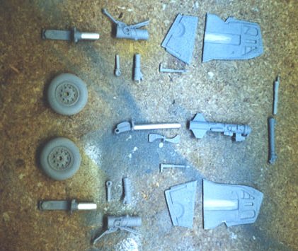 collar over the gear leg.
This is a good way to mount the gear and will give me some latitude in the
mounting process. This isn’t hard, but it takes time and research. Again, Lou
Drendel's book on Navy Phantoms has a good picture of a VX-4 bird with the gear
in transit on page 40.
collar over the gear leg.
This is a good way to mount the gear and will give me some latitude in the
mounting process. This isn’t hard, but it takes time and research. Again, Lou
Drendel's book on Navy Phantoms has a good picture of a VX-4 bird with the gear
in transit on page 40.
2.Nose landing gear.
Pretty much the same situation here but you must cut the nose scissors as well as the retract strut. Modification of the base of the metal portion of the nose gear fuselage mounting bracket is also required, Again easy if you’ve done your homework and some pre-planning. Cutting of the scissors takes care and planning. Be careful to do it right the first time and you won’t have to buy new parts, (hint, hint). Aluminum tubing was again used to extend the nose strut.
As far as I can tell, The main difference between the B and J main gear is the width of the tire. The Detail and Scale Navy F-4 book shows both types, make your own determination regarding any changes. I left mine as they came from the kit.
3.Retract struts.
The kit retract struts (parts B9&10) were cut and drilled so the retract portion could be moved inside the oleo. The smaller portion moves up inside the larger one.
4.Main gear doors.
CAM missed on these also! However, the shape of the forward upper portion is incorrect and I had to add sheet plastic and sand it to the proper contour. When I sanded the outboard side, jillions of pinholes appeared. I filled and sanded until they were gone and then primed them. Without-scratch building new ones, they’ll have to do.
 5. Main Wheels & Tires.
Cam didn’t do these right either. The narrow tires they provide are on Air Force rims!!!!!!!!!!! I was lucky enough to find the proper ones through my Amigo, Eli Raphael in Mexico. He’d already done the hard work and was kind enough to send me a set. Without him, I’d probably still be wishing I’d have returned the whole messy conversion kit.
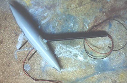
6. Centerline drop tank mounting and wire conduit.
In order to make a model LOOK like it’s taking off, it has to be OFF the ground!!!!!!!!!!! DUH………….to TRY to capture this feeling, I used a piece of broom handle, drilled holes in it, epoxied some thick copper wire in the holes and then hot stuffed and epoxied this thing to a cradle that was welded to a piece of steel tubing. I epoxied and hotstuffed the kit drop tank to this THING. I even had the foresight to make sure that I used hollow tubing and didn’t fill the hole for the wires with epoxy. I think I get a gold star for thinking ahead!!!!!!!!!!!!! I’ve actually had the model mounted to the mount/drop tank and it works!!!!!!!!!!!
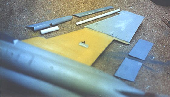 7. Port and starboard
leading and trailing edge flaps.
7. Port and starboard
leading and trailing edge flaps.
The first thing I did when I began this
model was to cut away all the high lift devices. I used the Tamiya upper and
lower wing halves because the injected parts are much stronger than the resin.
The removal procedure is the same for both sides. I added round plastic tubing
to the trailing edges of the lead edge flaps and the same stuff to the lead edge
of the trailing edge flaps. Confused? Good !!! Next to removing the wing bulges,
this takes the longest amount of time. I just kept at it ‘till I had them right.
Detail and Scales’ Navy F-4 book will show just enough detail to get you
started. I found this to be the most tedious of all the mods I made (cut and
fit, fit and cut) and I still didn’t get it 100% right. I’ll let you figure out
what I missed. 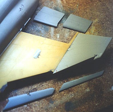 Remember,
whatever you do one side of the wing, you must do to the other. They’re
symmetrical.
Remember,
whatever you do one side of the wing, you must do to the other. They’re
symmetrical.
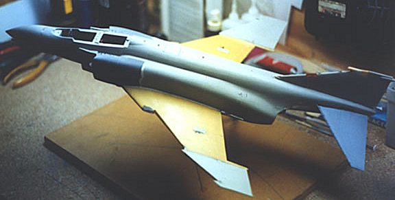
The last picture is the MONSTER before priming (see the top of the page). The yellow resin parts are CAM parts and the dark gray are Meteor intakes. This thing is so big it almost fills my work area and I hope, with a little luck it MIGHT end up as I pictured it some 25 years ago when the Revell kit and hand painting were the only game in town.
I don’t know what/when the next installment will be so ‘till then,
Aloha, Mike