Don’t Shoot me I’m only the piano player! Pt.
II.
BY Mike Wilson
In the first installment, we started the conversion of the 1/32nd Tamiya F-4J to a B. The process has been drawn out due to a bitterly cold Southern California winter (The Red Cross sent light sweaters to help with the emergency situation, Ed) and other reasons. However, we shall endeavor to soldier on and complete the beast.
Before we start, I’d
like to address Mr. Van Aken’s vicious personal attack regarding (his words) my
GLACIAL rate of model building. Large models take longer to build. Scott has no
idea about what “real” modeling is. He seems to think that if it can’t be built
in less than 24 hours, it’s not “modeling on the edge”. Don’t be fooled!
“Glacial” is best! (The editor considers the source on this one and deigns to
provide a proper response…Ed)
The saga continues:
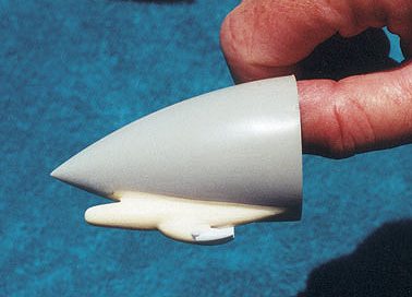
Undernose RHAW antenna. The CAM part was too large and the wrong configuration for the bird I’m building. Be sure to do your research before you do any cutting. There are at least 3 different Navy I/R seeker configurations. A good example of the one I used is on page 58, upper, of Lou Drendle’s ……And Kill MiGs, third edition. See photo on right.
Under wing and lower intake RHAW bumps. During Viet Nam, Navy F-4’s were equipped with RHAW antennas that were the same configuration as part #’s J-5 and J-3. They were mounted on the Port and starboard lower wings and bottom of the engine intakes. My friend Jack Kerr made a mold of these parts and cast them in resin for me. I might add that part #’s J-10, J-6 and J-4 were not the type of RHAW antenna housings used until the Viet Nam war was over.
 Meteor resin intake install.
I needed to add a lip of sheet plastic to the fuselage because I had to remove
the molded on lip when I installed the Seamless Suckers. This is a simple matter
and should present no problem.
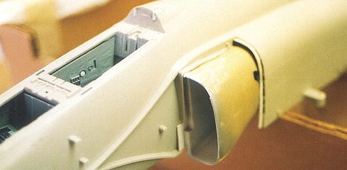
Meteor resin intake install.
I needed to add a lip of sheet plastic to the fuselage because I had to remove
the molded on lip when I installed the Seamless Suckers. This is a simple matter
and should present no problem.
See photo to the left.
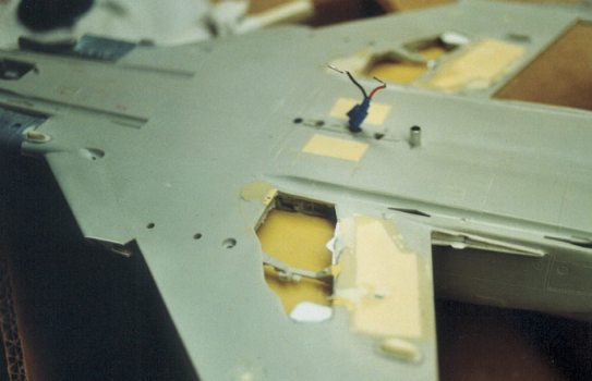
Under wing tire bulge removal. Fill the backside of the area around the gear well opening, with Bondo covered with sheet plastic. Use glue as required to insure a good bond and allow to dry for as long as it takes. Use hot stuff, liquid glue or tube glue. I used all three. After this dries, flip the wing over and figure out how to remove the tire bulges. I’ll share with you how I did it. I had access to a drill press and a flat end mill.
I chucked up the mill, set the height of the cut I wanted and made my first pass by moving the lower wing around. I reset the height and made a second pass. I kept resetting the cutting height until the bulges were removed. It’s best to remove small amounts of material at low speed to avoid a problem. I have no suggestions how to do this other than the way I did. I thought about it and decided this was best for me. Some of the gear well outline may be removed during this process and you may have to replace it with sheet plastic, I did. See photos below
 |
 |
Upper wing. I used the CAM resin upper wing provided in their conversion kit. I had to do a lot of work on these. You may find that modifying the kit upper wing is easier I think it would be in retrospect. The CAM wing is very warped and brittle. It’s also very weak requiring a great deal of reinforcement. Please note that you’ll have to do a lot of trial fitting and removal of kit plastic and resin of the conversion kit as well as reinforcing of the wing assembly to get everything to fit well enough to work. As I said, you may want to modify and use the kit wings.
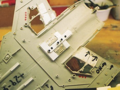
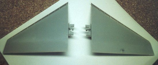 Horizontal Stab. I chose to
putty the seam between the fuselage and exhaust area, called the “tail section”
on the plans, to mount the stab, It’s necessary to cut it in half, (see photo to
right). Once cut, you’ll have to do a little modification of the mounting on the
stab and in the fuselage to get it to fit. It takes a little time and patience
to do this.
Horizontal Stab. I chose to
putty the seam between the fuselage and exhaust area, called the “tail section”
on the plans, to mount the stab, It’s necessary to cut it in half, (see photo to
right). Once cut, you’ll have to do a little modification of the mounting on the
stab and in the fuselage to get it to fit. It takes a little time and patience
to do this.
Front cockpit. The B front cockpit is very similar to the C. Luckily the C parts are included in the J kit, #60306. On page 19 of the plans is a portion of the F parts tree shown in dark gray. From this tree, use part #’s 31and 19. You’ll have to make the gun sight reflector from clear sheet to fit part 19. Use parts H-18 and H-17 from the J kit for navy type SAM warning gear. On page 35 of the Detail and Scale Navy Phantom book are pictures of a B/N front cockpit. Use these a guide for the proper configuration of the glare shield, gun sight, AOA indexer and SAM warning gear. You’ll have to mix the C parts along with the J parts for a “very close” Navy B configuration.
Rear Cockpit. Again, page 35 of the Detail and Scale book is your best reference. The B/N rear cockpits are almost alike. These photos explain the differences far better than I can. Particular attention needs to be paid to the B/N radar scope, compared to the J/S. The rear c/p is a much more extensive re-work than the front c/p. The pictures in Detail and Scale show it far better than I can explain . SAM warning gear was not fitted to very early F-4’s. This holds true for the front cockpit as well.
That’s about it for this installment. Next time, nose and main gear modifications, narrowed main tires and wheels, leading and trailing edge flap mods await us. How can modeling be this much FUN??????. Also if you think of a better way, let everyone know, if you think I’m crazy, tell my ex-wives, I’m sure they’ll agree. (I know your editor does! Ed)
Happy Trails