For a look in the box and a short history on the type, please visit the preview.
Already read this page? On to page 2
Now there are probably several of you who are wondering why I would want to waste my time building a dinosaur like the Airfix Sunderland. It is true that this is by no means a new kit. The date stamped on the inside of the wing is 1960, a date that may well be prior to your own appearance on this planet. The last time I built this beastie, the kit was less than 10 years old. At the time, I was very proud of my accomplishment. Naturally, I had taken all the care required of a youngster at the time and while I'd not bothered with painting it (it is mostly white anyway), I did manage to get all the decals on and in pretty well the right place. Even better, I got the turrets and the bomb racks to work! I was off hunting phantom U-boats with great vigor. It must have been quite effective for there has never been a ship sunk by a U-boat in Southern Illinois Obviously due to my dedication and ever-vigilant Sunderland!
Another reason for building this kit is that White Ensign produced three excellent etched brass sets for this kit. You can see them here, here, and here. The letter accompanying these sets contained several hints that it would be much appreciated if these sets would actually be used in a build article. Rather than send them off to someone else who may or may not actually build the kit (lack of return articles on sent out review kits is the reason I stopped offering them), I decided to tackle this one myself. It provides several opportunities. One is to see what WE PE is actually like, as it looks great on the frets. Another is to return to an old friend after many decades. Third is that if I do an article, I'm sort of forced into actually completing it. There are several multi-engine kits in my 'half-built' pile and I didn't want this one to join them! So off I go and ask that you join me on this adventure. It is bound to be a good one.
|
CONSTRUCTION |
Installment 1
Even though I'd bought this kit new in the mid-1980s, it has made a lot of moves. Typical of these older kits, all the jostling around had caused most of the parts to depart the sprue. While doing so, they managed to remove most of the blades from three of my props. An impassioned plea was made for info on replacement props, and Kevin Smythers responded with an intact set since he is going to do his with 'spinning' props. I'm quite grateful for his kindness, a typical reaction from modelers in general. With a complete kit in hand it was time to get things underway. I should mention that most of the 'in work' images will be treated as thumbnails. I know that some don't like these, but for this kind of an article, it will be best for all as you won't have to wait for full size images to load up every time you visit. I know those of you who are like me and stuck with a dial-up will appreciate that.
 Well,
the first thing one has to do is to extend the small 'lip' on which the
kit cockpit sits. The etched brass one is over twice as long so needs to
have more room on which to sit. .040 strip (forty thousandths) is
recommended, but I didn't have any. I used .030 instead and it looks as
if it will fit. I had to remove the little end tabs as well. No mention
was made of length, but the drawing shows it going nearly to the depth
charge bay doors. Since I'll be including this piece, having the little
lip a touch short seems OK.
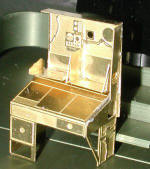
The instructions next suggested installing the right side interior piece first. Well, I cut the bit out and then realized that there were several lumps and bumps that should be removed first. I did a semi-short scraping session with a curved X-acto blade to where the part would fit fairly well. The fuselage in this area is not flat so the part will be curved when it is glued in place. Then I noted that it seemed to fit fairly low and so I wasn't sure if it would actually fit without interfering with the cockpit floor. Only way to verify that would be to build the initial stages of the cockpit.
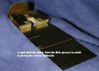 This
meant cutting out the large floor area, the smaller platform and a bit
that fits between the platform and the floor where it goes into the
stairway to the lower level. Using a pair of flat-nose pliers, I bent the
various bits and cemented them in place with super glue. I recommend
sanding all the edges to get the best fit. I normally cut etched brass
with small scissors and then sand the little nubs. Doing so with this set
will enhance its ability to fit properly.
When it was done, I started to test fit it. The instructions are not totally clear as to whether the etched floor fits atop the support strips or if it is supposed to fit under them. All of the bulkheads have small square sections removed just where they meet the floor so it is possible that they fit under and the support strips are visible. I've sent off an e-mail to WE who are contacting the designer of the set to get me the right answer. And that is where I left off for this session.
Installment 2
While awaiting word on the proper
installation of the floor, I've gone and started some construction of a
few of the other parts of the kit that won't be affected by the
photo-etched parts. This basically means flying surfaces. First to be
glued were the fin and rudder. I then
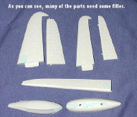 went
on to doing an aileron, an elevator, a tail plane (on the same side as
the elevator) and the floats. When dry, the edges were sanded smooth and
the parts carefully inspected for seams and sink areas. As you can
well imagine, those sink areas found are opposite the alignment pins. I
also found that both floats had poor upper seams that needed filler.
The real problem with a kit like this is just how to deal with sink areas. In some areas, such as I found on the flight control surfaces, the underlying detail is basically raised lines. These can be easily replenished after sanding by simply scribing them with a hobby knife blade or other method. The resulting area blends in well with the previously untouched detail. However, it is quite another situation when dealing with those areas that are festooned with rivets. It is inevitable that this detail is going to disappear under filler and sand paper. So what can be done to restore these small, raised pips without resorting to some long and tedious process? My initial thought was to replace them by taking a small (#80) drill bit and using indented areas to represent the rivets. Not sure just how that will look in the end, so if you have any suggestions, I'd welcome them. Please post your ideas on the Forum if you have access to that medium.
Hopefully by the next installment I'll have recieved a reply to my inquiry. If not, there are still a number of other bits that can be worked on until such a time that I hear from the designer of the set, so stay tuned.
Installment 3
Still haven't heard from the designer on the proper placement of the floor so took the opportunity to finish working on some subassemblies. The floats needed a second application of filler on the sink marks on the underside and I did finish sanding and restoring some of the detail on the control surfaces. I was not at all amazed that the various detail bits didn't match from one side to the other!
Several folks have suggested a gizmo
called a ponce wheel to replace the missing rivets. Others have
recommended sanding the whole thing smooth and rescribing the panel
lines, but I'm not sure that I've the constitution to do something quite
like that. Some of you will notice that I've glued the elevators to the
horizontal stabs. Big aircraft like the Sunderland
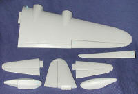 used
gust locks on their controls to keep them from banging around in a wind
so it would be the norm to see the controls in the neutral position when
at anchor or on the beach.
As you can see from the picture, I've managed to get both tail planes as well as the fin and rudder done. One wing has been assembled with its aileron as well and the other aileron has been assembled. I did those separately so I wouldn't get the sides wrong. I can tell you that it is nice that Airfix numbered all the largish parts as with them mostly off the sprues and floating around in the box, it could have been difficult.
Installment 4
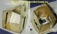 With still no info on the proper way to
install the cockpit floor (and I'm waiting because I want to be sure I do
it right), I decided to take the time to put together the bomb bay area.
This is really quite simple as the entire structure is really only two
pieces. One is the forward bulkhead and the other is the roof, aft
bulkhead and floor all rolled into one part. After some careful bending,
I glued the two pieces together and then placed it into the left fuselage
half. The small tabs that hold in the 'door' to the wing help to align
the bay area. Be sure to get the floor straight and line up the aft
bulkhead to fit the curve of the inner fuselage. I didn't and had to cut
away the superglue in order to get it to fit properly. Once it was in
place, I flooded the outer seams with superglue to keep it there.
 While still working with the bomb bay
fret, I cut the bomb racks from their mounts. Then I sanded the mount as
smooth as I could so that it would be able to accept the brass fret that
fit in its place. I recommend care when cutting off these racks as I had
several of them go flying when I snipped them off. Fortunately, I do wear
eye protection and I recommend it to you as well when you are cutting
things like this. Once the area was sanded smooth, I attached the two
brass plates that fit there. While that was drying, I glued on the doors
to the bomb bay area. On hindsight, it may have been easier to do these
before bending the sheets, but nonetheless, once in place, they looked
quite nice. I'm not sure why the upper door was even provided as I don't
think you'll be able to see it at all when the fuselage halves are
joined.
Installment 5
 Much
to my embarrassment, I've been informed of the proper fitting of the
cockpit floor and (had I read all the instructions first), I'd have found
out that they do fit under the new runners put into the fuselage
halves. Meanwhile, I did more work on the bomb rack assemblies by first
installing the brass mounting plate, then attaching the racks themselves.
Fit is quite good as there are guides
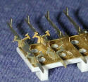 to follow, but you must be sure the
mating surfaces have no little stubs sticking up or you won't be pleased
with the results. File the surface smooth on the rack mounting area. I
also started adding on the little anti-sway brackets. It will take some
time to get them all on as they aren't the easiest to clean up!
I also started work on other parts
by assembling the stairway to the lower section of the nose. The
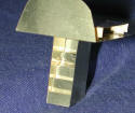 additional bulkheads were cut off in preparation for assembly. The
instructions intimate that the bulkheads are to be glued in place,
and then all the detail work added to them. This seems counter-intuitive
as I'd think it would be difficult to get the detail bits properly in
place. I also started on the radio operator's console, but just did a
tiny bit on that.
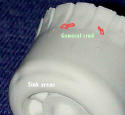 Meanwhile, I have also been working on
other airframe parts. The other wing has been assembled and filler added
where needed. I also started cleaning up the engine cowlings. Most are ok
with just some small lumps of plastic from where the mold has slightly
corroded, but one has a mass of sink marks on the forward section that
needed quite a bit of filler. Though going slowly, progress is being
made.
After several months of doing nothing on the kit, I went back to work with folding and gluing etched brass. I have to tell you that it is slow going for me as I'm not that proficient with etched brass and so have some trouble with it.
I spent many hours on various bits so
let me give you a rundown of what went on. I worked on the Radio
Operator's table. The radios have to be built up with plastic card and
then have the faces affixed. I got the various racks ready for the
radios. They did not fit into the allotted spaces as well as I'd have
hoped so I'll probably have fit problems when it comes time to glue the
bulkhead on which it sits into the
 fuselage.
I also did the instrument panel. This
construct requires you to attach the panel to plastic card and then bend
the anti-glare panel over it. Not an easy task. I pre-bent the panel and
then attached it. It worked out a lot better. I also worked on the
throttle quadrant. The upper piece of this is in
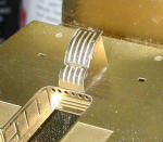 an
open 'M' shape and with all the bending I had to do, I broke it in two
parts. This may have been a blessing in disguise as I found it a great
deal easier to attach to the rest of the pedestal in two pieces vice one.

I also built up the upper instrument panel that goes under the canopy. This is also a rather fussy build and didn't turn out as well as I'd have liked.
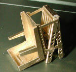 What
did turn out really well was the pilots seat. This is several small
assemblies glued together and it really looks the part.
Turning to the Navigator's position, there are yet more black boxes that have to be built and this is really tedious. I don't know why the boxes themselves couldn't have been part of the etched fret, but perhaps it was a lack of available space. It really would have been a LOT faster and a lot less hassle.
