
| KIT #: | FR011 |
| PRICE: | $16.98 |
| DECALS: | Three options |
| REVIEWER: | Scott Van Aken |
| NOTES: | Short run kit with photo etch and vacuformed part. |
| HISTORY |
The PZL P.24 was developed as an export version of the PZL P.11, a gull-wing all-metal fighter designed by Zygmunt Puławski. The P.11 was powered with a license-built Bristol Mercury engine. The license did not permit export sales, so the French Gnome-Rhône company proposed using their engines in the P.11. The first P.24/I prototype, based on the P.11a and powered by a Gnome-Rhône 14Kds 760 hp (570 kW) engine, was flown in May 1933. The second P.24/II prototype, named the "Super P.24", set a world speed record for radial engine-powered fighters (414 km/h). The third P.24/III prototype was the "Super P.24bis" with a more powerful 14Kfs engine. The type was shown at the Paris air show in 1934 attracting great interest from the participants.
 The aircraft was conventional in layout, with high wings. It was all-metal and metal-covered. The wings had a gull-wing shape, with a thin profile close to the fuselage, to provide a good view for the pilot. This configuration was developed by Zygmunt Pulawski and called "the Polish wing". The canopy was closed (apart from prototypes). An internal 360 liter fuel tank in the fuselage could be dropped in case of fire emergency. It had conventional fixed landing gear, with a rear skid.
The armament was a combination of 20 mm Oerlikon FF cannons and 7.92 mm Colt-Browning machine guns in the wings.
| THE KIT |
 There have been several P.24 kits in 1/72 from a variety of manufacturers in both injected plastic, resin and vacuformed plastic. Your editor built one of unknown origin 20 or more years ago that was rather crude, to say the least.
This particular kit puts all previous efforts to shame. The kit is superbly molded by our friends at MPM as part of their Azur series and allows the builder to complete either a P.24B or a P.24E. The major difference in these two is the shape of the cowling as both are powered by two row Gnome-Rhone 14 cylinder radials. This was an extremely popular French engine of the time and powered a staggering number of aircraft, including several wartime German planes such as the Hs-129.
The kit comes on two grey injected sprues with a clear sprue for the one-piece canopy. There are also two vacuform canopies for those who want to cut the canopy open. Several resin sprues contain exhaust, oil coolant radiators, engine gearbox hub, machine guns, shell ejector chutes and some other very small items. The etched fret includes the straps that go over the radiators, trim tabs, control hinges, seat harness, rudder pedals, and a few other detail items.
Since there are two variants offered in the kit, the differences between those two have been taken into account. The B version will have the shorter, more rounded cowling, wheel pants, three bladed prop and the added shields to the back of the exhaust. For the spatted gear, only lower wheel bits are provided and can be added late in the build if one wishes. There are armament differences as well so you really need to choose the variant you will be building early in the construction process.
 A few things I noticed. One is that there are ejector towers on all the large pieces. This means the inside of the fuselage and the inside of the upper and lower wing halves so you will need to remove those. I was also impressed at how well the corrugated surfaces were done. Thankfully, these corrugations do not extend over the wing leading edges. I also noticed that there are no pushrods on the engine, nor do the instructions show these needing to be added. It will add a lot to the engine if these are added; at least to the front row, but it is your choice. This would have been a nice p.e. or resin addition.
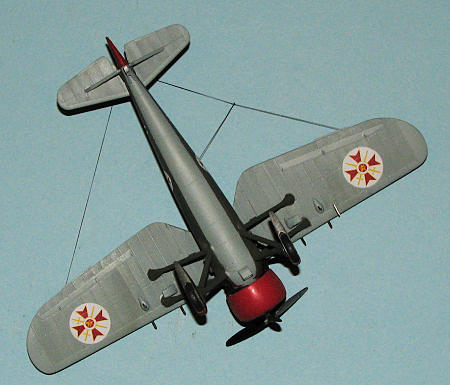
Instructions are very well done with several detail drawings to show alignment. Any modification needed is clearly shown as are any optional bits. The gear legs will require some rigging so be aware of that need. The markings are provided for three aircraft. One is a pre-war Bugarian AF version with a large red speed stripe and cowling in Dark Green over Light Blue. The two Romanian versions are quite similar in Dark Green and Dark Earth over Light Blue. These both carry Eastern Front markings consisting of a yellow fuselage band, lower wing tips and cowling. The big difference is the style of insignia. The decals are superbly printed; very crisp and in register.
| CONSTRUCTION |
First thing I did was to assemble the wings. It is important that one sand down the ejector towers in the middle and end of the wings or the halves will not fit. Also be sure to slightly squeeze the wings by using tape running from wing tip to wing tip. This will get a decent closure of the inner seam so you won't have to use filler. Filler on corrugated surfaces never looks right.
 Then the interior was built up. Much of the work here is in photo etch and I have to say that the parts are quite small. I worked as carefully as I could and still lost the instrument panel brace to the carpet monster. Small as these pieces are, even more tiny ones are to come. Thanks to all the p.e., the time it would normally take me to do a simple cockpit like this easily tripled. In fact, that is pretty much true of any kit with resin and photo etch, at least for me.
With the cockpit built up and the interior painted (mostly aluminum), the fuselage halves were joined and filler used on all the seams. There are two resin radiators for the forward fuselage. These were cemented in place. There is no clear attachment point; one just puts it where it looks like it will fit according to the drawings. Two insanely thin and too short photo etch straps are then somehow glued to the fin area of the radiators.
Back at the wings, there is yet more resin and photo etch to be attached. I had decided to build the Bulgarian P24B so when attaching the resin shell ejector ports (again, with no clear delineation of where they fit), the ones with the extended ports fit on the inside. Do not install these too far forward or they will interfere with the struts. I fit these on first and then tried to line up the outer ones with them.
 Now for the ridiculously small aileron hinges. These are literally smaller than your standard pin head and take a lot of effort to install. I used a wet detail brush to get them into position in the cement. Of course, the aileron trim tabs are also photo etch and quite easy to knock off with handling.
Once all that was in place, the wings were cemented in place and the wing struts glued in. I made sure the mounting holes were enlarged to be sure the tabs fit as the ones molded in place are too shallow. There is quite a gap where the upper wing meets the fuselage forward of the cockpit. This was, in due course, filled and smoothed out.
I moved to the rear and attached the tail planes and the tail skid. This skid has a resin vertical post and an injected bracing. One thing I did have to do was to enlarge the attachment hole for the resin post. I then glued on more ridiculously small etched control actuating rods and the rudder tab (which I knocked off several times).
 I chose to use the attach the main gear at this time and will once more remind you that you need to enlarge and deepen all the plastic attachment points somewhat. The struts took a bit of fiddling to get in place. Instructions show they need to be 34 mm apart, but does not mention if this is with or without the wheels or if this measurement is for the inside or outside. I then attached the wheel covers. There is a small gap at the top of these and I am thinking that perhaps sanding down these should have been done. No photos in my reference show this area so it may well be accurate. I did not rig the main gear nor attach the stabilizer supports at this time to make painting a bit easier.
Last things prior to painting was to install the engine in the cowling halves and then mask and install the canopy. The engine is too large in circumference to fit into the cowling halves as there is about a 1/16" gap. This meant sanding on the top of the engine all around to reduce the diameter until it fit into the cowling. This was then masked off. The canopy is in need for some frame lines on the forward part of the injected canopy as there are none. You pretty well have to guesstimate where the lines would be when masking the forward section. I also had to trim both the canopy and attachment area to get a fairly flush fit. I also attached the lower intake. This needs to be right up against a seam just prior to where the forward fuselage curves drastically inward for the engine mount.
| COLORS & MARKINGS |
 Colors for this are given in Gunze references. The red for the cowling was painted using Humbrol paint that crossed using the ever-helpful IPMS Stockholm cross references. It looks too bright to properly match the duller red of the decals, though it is a perfect match for the Gunze paint that is referenced. The upper color goes to RLM 71 while the lower matches RLM 65. I used Testors enamels for both of these, painting the RLM 65 first. Then there was a great deal of masking required before the RLM 71 as the main struts are the upper surface color. I'm sure there will be much touching up required once the masks are removed.
| FINAL CONSTRUCTION |
 Once the paint was dry on the engine and cowling, I painted the exhaust with Alclad 'exhaust manifold'. When it came to fitting these two pieces, one has to reduce the straight sections that lead into each collector down to 1mm in length or the pieces will not fit. The exhaust sections do not really fit onto the engine anywhere and are simply glued to the inside of the cowling. Much fiddling needs to be done as one wants to have them properly positioned. The exhaust will exit between the wing and gear struts. You also need to keep the cowling hinges horizontal. I had to cut away the alignment key on the fuselage as it did not match the engine key. Once I was happy that it would fit it was set aside while I dealt with the decals.
These decals are superbly printed and quite thin. I started with one of the rudder stripes. This piece had to fit over the photo etch actuator, which it did after several applications of MicroSol. It is actually a bit over-size, which is nice as I'd rather have a tad too big than too small. It allows for complete coverage. Once that was done, I applied the first of the fuselage flashes. These have to be cut where the side fuselage radiators are fit and the best way to do that is after they have dried. Use no setting solution so once cut they can easily be peeled away. I continued to add the decals as time went on. Be sure the lion on the insignia points up/forward. For the spat decals, well, in hindsight, it would be best to put on the spats AFTER you apply the decals. The decals did not want to meet at the top or at the front for that matter, leaving a large gap.
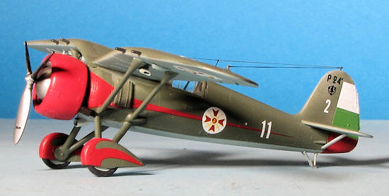 Looking at the need to paint some of the red decal area on the spats and to make the side ones more complete. I opened a tin of Humbrol #19 gloss red. Much to my surprise, it seemed to be a perfect match. Armed with this knowledge, I got a broad brush and repainted the cowling, which turned out much better.
Now a ton of more stuff to do. The wing gun holes had to be enlarged so the guns would fit. The tail struts are too short. I drilled holes for the photo etch gun sight pieces and glued those in place. I also painted the wheel sections and glued them in place. The venturi tube was glued onto the fuselage. I drilled a hole in the fuselage next to the canopy for the radio wire and then used E-Z Line for the radio wires. A bit more touch-up painting then the engine/cowling was attached. Actually, the engine section was glued on by the exhaust collectors as it would not reach far enough to actually match up with the engine. A coat of semi-matte was sprayed on and the masking removed. I forgot to glue on the gear wires. Bet you did not realize they were not there until now.
| CONCLUSIONS |
This one takes more work than what initially presents itself. This is due to the miniscule photo etch parts. I know there are people who revel in this stuff, but I am not a fan of teensy-weensy pieces and will be leaving much of this sort of stuff off my next build that includes it. Bigger stuff I can handle. Regardless, now that it is done, I have a very nice model of an important Bulgarian aircraft. I also draw a lot of satisfaction from the build as I was able to overcome quite a few personal hurdles in getting it completed.
| REFERENCES |
http://en.wikipedia.org/wiki/PZL_P.24
PZL P.24A-G by Andrzej Glass, Kagero Publishing, 2004, ISBN: 83-89088-33-9 October 2011
Thanks to www.westcoasthobbys.com for the preview kit. Order yours today.
If you would like your product reviewed fairly and fairly quickly, please contact the editor or see other details in the