Hasegawa 1/32 Bf-109G-10 ( with type 110 cowling)
| KIT #: | 08068 |
| PRICE: | $39.95 MSRP ($35 from -) |
| DECALS: | Two options, both Eric Hartmann |
| REVIEWER: | Scott Van Aken |
| NOTES: | Cutting Edge 32139 conversion set used. |
| HISTORY |
 Though the Bf-109G-14 is the kit used, this is a Bf-109G-10. The G-10 was
probably the most interesting of the109 series produced. These airframes
were partially rebuilds of older airframes, but mostly new build
construction. What was done
was that these aircraft were brought up to 109K-4 standards as much as could be.
G-10s are
difficult to tell from late G-6s and G-14s unless one could read the serial
numbers as these reconstructed air frames
got new serials. Thanks to information from Ferdinando D'Amico, I have
learned that the G-10 was produced new in large numbers, which is new
information to most of us who thought they were all reconstructed
airframes.
Though the Bf-109G-14 is the kit used, this is a Bf-109G-10. The G-10 was
probably the most interesting of the109 series produced. These airframes
were partially rebuilds of older airframes, but mostly new build
construction. What was done
was that these aircraft were brought up to 109K-4 standards as much as could be.
G-10s are
difficult to tell from late G-6s and G-14s unless one could read the serial
numbers as these reconstructed air frames
got new serials. Thanks to information from Ferdinando D'Amico, I have
learned that the G-10 was produced new in large numbers, which is new
information to most of us who thought they were all reconstructed
airframes.
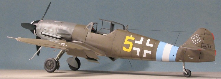
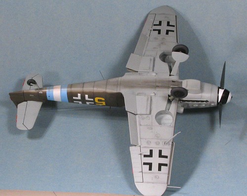
Things in common with all G-10s was the lack of the cannon bulges on the upper cowling, the use of an Erla Haube canopy (the one without all the framing) and a taller wooden fin and rudder. The wheels could be the wider ones like the K and some G-14s, in which case there would be the wide strip down the wing to cover them, but not all G-10s had this feature. In fact, most did not. There could also be a taller tail wheel strut. Most G-10s did have this option, but again, that wasn't always the case.
The G-10 did have two different types of cowlings. The real way to tell the difference between the two is to look at the left side of the fuselage just under the windscreen. The most common type had a fairing that curved on the underside. This is the 'type 100' cowling. If you have built the Revell 1/48 Bf-109G-10, or the new Hasegawa 1/32 Bf-109G-10, then you've built one with the type 100 cowling. The other, which is what is on this conversion, is 'taller' and flat. It does not have a curve and extends the full height of the fuselage. These 'type' numbers were not used by the factory but are a concoction of Jean-Claude Mermet, who did the ground breaking research on this several years back.
| THE KIT |
For a preview of the Hasegawa 1/32 Bf-109G-14 kit, please follow this hyperlink.
| CONSTRUCTION |
 In
order to use the Cutting
Edge 32139 conversion set, one must start with the Hasegawa 1/32
Bf-109G-14 kit. The instructions are pretty imperative on this and tell you
not to use any other. I started by cutting off all the resin pour stubs
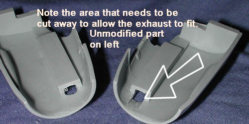
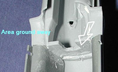
from most of the pieces. Then the cowling sections need more attention. In
order to get the exhaust to fit, you have to file grooves in the forward
section. Don't worry about filing too much as the resin is quite thick in
this are. As you can see, much needs to be removed.
In
order to use the Cutting
Edge 32139 conversion set, one must start with the Hasegawa 1/32
Bf-109G-14 kit. The instructions are pretty imperative on this and tell you
not to use any other. I started by cutting off all the resin pour stubs
from most of the pieces. Then the cowling sections need more attention. In
order to get the exhaust to fit, you have to file grooves in the forward
section. Don't worry about filing too much as the resin is quite thick in
this are. As you can see, much needs to be removed.
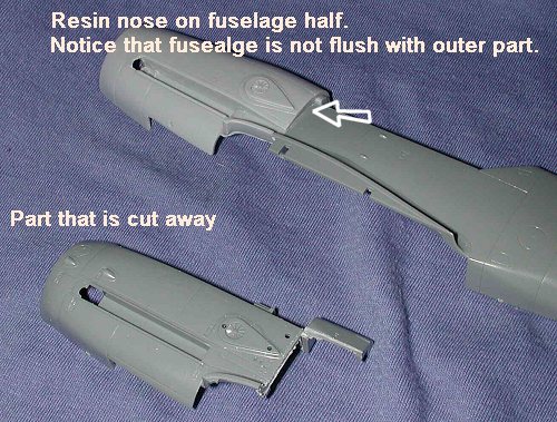 After
that, I cut away the kit's fuselage as indicated in the instructions from
the Cutting Edge set. The upper section just in front of the canopy bits
has to go as well. A resin replacement part that is sufficiently wide is
provided. You'll notice that the proper fit of the fuselage into the new
resin nose has it sitting below where you'd think it should go. This is so
that the resin fairing can fit in place. It is like this on both sides.
After
that, I cut away the kit's fuselage as indicated in the instructions from
the Cutting Edge set. The upper section just in front of the canopy bits
has to go as well. A resin replacement part that is sufficiently wide is
provided. You'll notice that the proper fit of the fuselage into the new
resin nose has it sitting below where you'd think it should go. This is so
that the resin fairing can fit in place. It is like this on both sides.
Then it was time to start building the kit as one normally does. In spite of using an aftermarket conversion, I decided not to use an aftermarket cockpit. There are nice ones out there and I'm sure that many will go that route. They do give a bit higher standard of detail over the kit version, but the kit cockpit isn't that bad at all and really only needs to have seat belts added.
Anyway, I started by gluing the
various bits to the cockpit side walls. I also opened up a section of the
fuel line that runs from the drop tank up along the right side of the upper
cockpit. This had a clear window so that the pilot could tell if fuel was
flowing from the drop tank or not. A piece of stretched clear sprue will be
inserted once everything is p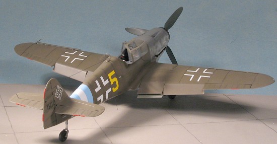 ainted. I glued in all the bits on the cockpit
tub that were to be painted RLM 66 (which was about everything). A pilot
figure is provided, which is nice, but I rarely use them.
ainted. I glued in all the bits on the cockpit
tub that were to be painted RLM 66 (which was about everything). A pilot
figure is provided, which is nice, but I rarely use them.
I then turned to the wings. The lower wings have a circular wheel opening (which I hope means an F model coming sometime in the near future), so you have to cut away the small triangular bits yourself. I also glued together the drop tank, wheels and tail section.
Back at the interior, I applied the instrument decals to the main panel and the sub-panel on the right side. I painted various boxes with flat black, the rudder pedals aluminum, the oxygen regulator blue and the fuel line yellow, using Vallejo acrylics for all but the aluminum. I also glued in place the lap belts from Cutting Edge 32093, which are very nice flexible belts. These stick to superglue like nobody's business so be sure to have them right where you want them before gluing. These belts were then painted with both acrylics and enamels. They hold paint quite well with no problems.
Returning to the wings, the radiator grilles were glued in place and the holes for the small wheel bumps were drilled out. I then went back to the interior and did some additional detail painting. I also stretched some clear sprue and cut off a tiny piece of it to insert into the drop tank fuel line. It really is quite small, but does look better than raw plastic!
 I
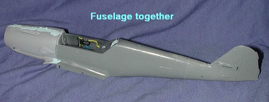
glued the tail section together and then the fuselage halves. The tail was
then glued into place in the slot at the back. Fit here is just as good as
it was with the G-6 I built now on two years past. With that in place, it
was time to grab the resin nose. It was glued using superglue. Fit isn't
bad, but not as good as the plastic parts would be. I used super glue as a
filler and sanded it down after hitting it with accelerator. I then glued
the fuselage to it, added putty where needed, and let it dry.
I
glued the tail section together and then the fuselage halves. The tail was
then glued into place in the slot at the back. Fit here is just as good as
it was with the G-6 I built now on two years past. With that in place, it
was time to grab the resin nose. It was glued using superglue. Fit isn't
bad, but not as good as the plastic parts would be. I used super glue as a
filler and sanded it down after hitting it with accelerator. I then glued
the fuselage to it, added putty where needed, and let it dry.
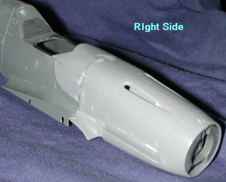 After
than was sanded down once more, I glued on the upper portion and the side
pieces. You do have to remove the two small tear drop shaped parts on the
left fuselage side as those were to mount the umbrella
After
than was sanded down once more, I glued on the upper portion and the side
pieces. You do have to remove the two small tear drop shaped parts on the
left fuselage side as those were to mount the umbrella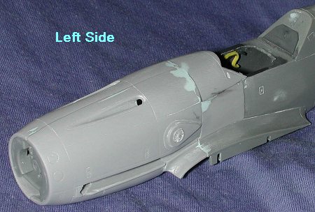 for the trop version and are not needed on the G-10. The fit of these parts
isn't the greatest and it could well be due to my poor sawing abilities.
There were gaps that needed to be filled in, which I did using superglue,
accelerator and then a final coat of regular putty. The panel lines were
rescribed later. Don't worry if there isn't the best tight fit against the
fuselage for these as late war planes were notorious for ill-fitting
panels. I also glued in the oil cooler. It doesn't matter how it is
installed as it won't be seen and is only to hold the prop shaft.
for the trop version and are not needed on the G-10. The fit of these parts
isn't the greatest and it could well be due to my poor sawing abilities.
There were gaps that needed to be filled in, which I did using superglue,
accelerator and then a final coat of regular putty. The panel lines were
rescribed later. Don't worry if there isn't the best tight fit against the
fuselage for these as late war planes were notorious for ill-fitting
panels. I also glued in the oil cooler. It doesn't matter how it is
installed as it won't be seen and is only to hold the prop shaft.
 With
that pretty well out of the way, I test fit the interior. It didn't fit at
all well and the problem was two-fold. One is that it now bumped up against
the resin backing on the nose section. This needs to be sanded down a great
deal prior to actually gluing on the fuselage parts. I didn't have th
With
that pretty well out of the way, I test fit the interior. It didn't fit at
all well and the problem was two-fold. One is that it now bumped up against
the resin backing on the nose section. This needs to be sanded down a great
deal prior to actually gluing on the fuselage parts. I didn't have th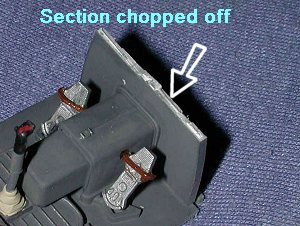 at
option as it was firmly in place, so I used a grinder attachment on my
motor tool to grind away as much of this resin as I could. It still wasn't
enough so I cut off part of the upper forward bulkhead on the interior and
that was what was needed.
at
option as it was firmly in place, so I used a grinder attachment on my
motor tool to grind away as much of this resin as I could. It still wasn't
enough so I cut off part of the upper forward bulkhead on the interior and
that was what was needed.
Next I glued in the instrument panel.
It no longer has the nice attachment point that was provided by the plastic
part and as a result only fits where it touches. It also seems a bit low,
as it won't fit all the way up against the underside of the resin part
(perhaps due to the fuselage s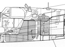 ides
being a bit more 'squeezed' to fit the new resin nose), but I didn't want
to start cutting on it. As a result, it is up there as far as it will go
and glued where it touches the sides. Not pretty, but that is what one has
to do. I also noticed that there is not a little 'bump' for the back of the
cockpit. You see, most G-10s had the water/alcohol injection system for
extra power. This meant adding in a new tank for the mixture and it was put
right behind the pilot. This resulted in a box-like protrusion on the back
panel (see drawing to left). Nothing is provided in the conversion set for
this so one has to add it on. Also missing are
the two small 'bumps' on the lower forward cowling which were put there to
accommodate the oil cooler lines to the larger oil cooler needed for the DB
605D engine. After contacting Meteor Productions
about this, I was told that those aircraft with the type 110 cowling did
not have these bumps as they were taken care of by the new cowling. This
necessitated a bit of additional research on my part as I was curious to
see what was going on about this.
ides
being a bit more 'squeezed' to fit the new resin nose), but I didn't want
to start cutting on it. As a result, it is up there as far as it will go
and glued where it touches the sides. Not pretty, but that is what one has
to do. I also noticed that there is not a little 'bump' for the back of the
cockpit. You see, most G-10s had the water/alcohol injection system for
extra power. This meant adding in a new tank for the mixture and it was put
right behind the pilot. This resulted in a box-like protrusion on the back
panel (see drawing to left). Nothing is provided in the conversion set for
this so one has to add it on. Also missing are
the two small 'bumps' on the lower forward cowling which were put there to
accommodate the oil cooler lines to the larger oil cooler needed for the DB
605D engine. After contacting Meteor Productions
about this, I was told that those aircraft with the type 110 cowling did
not have these bumps as they were taken care of by the new cowling. This
necessitated a bit of additional research on my part as I was curious to
see what was going on about this.
The Michulec reference was the first place I went. In the drawings section, the 110 cowling was shown without these bumps, but several profiles showed aircraft that did have them along with the 110 cowling. The AeroDetail book showed a drawing of a Bf-109G-10/AS with the 110 cowling and no bumps. This is corroborated by Green's 2000 book, though there is no mention of the G-10/AS. The final reference only states that there were not enough 605D engines for initial production and so the DB 605 AS was installed in its stead. According to this reference, unlike the G-6/AS and G-14/AS, these planes were not called G-10/AS but just G-10 so the AS addition is just there for reference.
With the G-10, Erla designed and produced a new, wider and more streamlined nose which managed get rid of the "chin" bumps made necessary by some of the oil lines for the DB 605D engine. It was the only of the two factories producing the G-10s (the other was WNF, as MTT didn't build this version) to use such modification, all the other WNF-G-10s using the standard solution, which was applied also to the K-4.
 So what does all this mean to you?
Well, what it means is that this particular conversion set was designed for
a G-10 that did not have the methanol injection
system installed. Can you do a DB 605D engined aircraft with the 110
cowling as provided here? Yes you can as there seems to be no difference in
the cowling configuration between those few DB 605 AS powered aircraft
(only 50 were made) and others. Just to toss in some more confusion, either short or long tail
wheel leg could be used with the 110 cowling. Some got all sorts of mods while others did not get the full
modification. To reiterate, the 'type 110 cowling' was used only on Erla
built aircraft and is used to identify aircraft from this factory. Well, back to the build.
So what does all this mean to you?
Well, what it means is that this particular conversion set was designed for
a G-10 that did not have the methanol injection
system installed. Can you do a DB 605D engined aircraft with the 110
cowling as provided here? Yes you can as there seems to be no difference in
the cowling configuration between those few DB 605 AS powered aircraft
(only 50 were made) and others. Just to toss in some more confusion, either short or long tail
wheel leg could be used with the 110 cowling. Some got all sorts of mods while others did not get the full
modification. To reiterate, the 'type 110 cowling' was used only on Erla
built aircraft and is used to identify aircraft from this factory. Well, back to the build.
I then glued in the cockpit and glued the lower center fuselage to the rest of the fuselage. I then noticed that the area with the new cowling was too wide and didn't fit back far enough, leaving a considerable gap at the leading edge of the wing. Test fitting the new radiator showed that the cowling was, indeed, too wide as it didn't want to fit. This tells me that I should have sanded the lower cowling join about 1/16 inch or even more to take care of these problems. When you do yours, dry fit the cowling to the lower fuselage center section to be sure that you have it narrow enough and that it isn't too far forward. You can also use your oil cooler cowling to check width. It will save you from having to do later fixes.
I did sand down on the wing root to
improve the fit and got it pretty close. On both wings I glued the
underside first, let it dry and then glued the upper surface. That seemed
to take care of any problems and using superglue on the resin sections
helped to fill in any seams.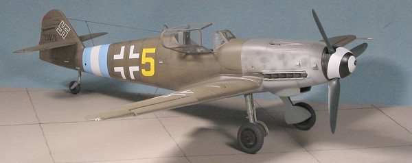
I then opened up the upper wing holes a bit more and installed the wheel clearance bumps. The taller Cutting Edge metal tail wheel was then glued in place and the wheel was removed from the resin block and sanded down in prep for painting. At this time I also assembled the main gear legs and got those ready for a coat of paint. The supercharger intake was also glued on and I went to work on the oil cooler under the nose. This area required considerable trimming to get the kit part to fit. It also meant that there would be no positive locators in the front as they were not part of the resin parts. I got it to where it was a very tight fit and when in place, was glued. The radiator housing was too narrow for the holes because the cowling was not narrow enough on the lower side. I should have done more dry fitting, but I didn't. Fortunately, resin is resilient so it was spread until it 'clicked' in place and then superglued before it could pop out. The gaps that were rather prominent in the back were filled with super glue and sanded smooth. I also filled, sanded, and smoothed the gaps along the side of the radiator housing.
The next part added was the windscreen. This has to have the little 'quarter windows' removed before gluing. I also had to remove the section just forward of the windscreen. When I test fit this part, it did not fit at all well and required a lot of additional carving and sanding. Frankly, I think it would have been easier to have the resin part cut to accommodate the kit's windscreen than to have to cut the windscreen to accommodate the resin part. It would have provided an area that could be filled in and smoothed out instead of leaving what turned out to be a bit of a gap that I tried to fill with white glue, but was not really that successful. I then masked off the canopy and windscreen using Black Magic set CEBM 32083.
| COLORS & MARKINGS |
 At this time, I still didn't have a
decal sheet to go along with the kit, but I was pretty sure that the
underside would be RLM 76 so I headed for the paint shop and painted the
underside, including wheel wells with this color. I also painted both sides
of the gear doors and lower antennas. Late war aircraft often had the wells
and inner gear doors painted with the underside color. Since there really
are so few photos of these features, it will be difficult for anyone to
tell you that your suppositions in this area are wrong. You could also do
the gear legs in RLM 76, especially if they were the parts that were still
on the plane from when it was a G-6.
At this time, I still didn't have a
decal sheet to go along with the kit, but I was pretty sure that the
underside would be RLM 76 so I headed for the paint shop and painted the
underside, including wheel wells with this color. I also painted both sides
of the gear doors and lower antennas. Late war aircraft often had the wells
and inner gear doors painted with the underside color. Since there really
are so few photos of these features, it will be difficult for anyone to
tell you that your suppositions in this area are wrong. You could also do
the gear legs in RLM 76, especially if they were the parts that were still
on the plane from when it was a G-6.
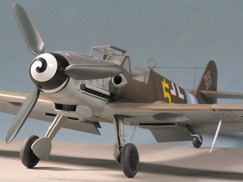
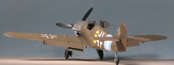
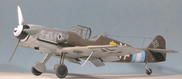
Having received the decal sheet I was going to use (Cutting Edge 32059), I had a choice of upper surface colors. They could be either overall RLM 81 or RLM 83. Since I hadn't done an overall RLM 81 aircraft, I chose this shade. After masking the RLM 76 bits I didn't want to have over-sprayed, I painted the upper surface save the cowling with RLM 81 from Testors Model-Master enamel range. The cowling was a replacement and it was in RLM 75 with the usual mottling. Since this was obviously a field paint job, the demarcation line on the lower fuselage did not have to be very sharp.
 After the usual back and
forth painting and going through the usual mound of tape, I returned the
kit to the work bench to have the landing gear attached. At this time, I
also glued on the pitot tube and the DF loop antenna. I'd painted the tires
using Floquil's Weathered Black and went to use the provided masks. The one
for the tail wheel seemed a bit small for the resin replacement wheel, and
the one for the main wheels didn't have the holes cut in them for the
wheels to stick out! The result was that I had to brush paint the main
wheels using Vallejo's flat black. The tail wheel worked out just fine and
I brush painted the part that was missed. It was at this time that I
noticed that the resin tail wheel wasn't round but was a bit lop sided.
After drilling out the attachment holes to several times their original
diameter, I spread the metal tail wheel forks and installed the tail wheel.
It is in such a position that the shape situation isn't noticeable.
After the usual back and
forth painting and going through the usual mound of tape, I returned the
kit to the work bench to have the landing gear attached. At this time, I
also glued on the pitot tube and the DF loop antenna. I'd painted the tires
using Floquil's Weathered Black and went to use the provided masks. The one
for the tail wheel seemed a bit small for the resin replacement wheel, and
the one for the main wheels didn't have the holes cut in them for the
wheels to stick out! The result was that I had to brush paint the main
wheels using Vallejo's flat black. The tail wheel worked out just fine and
I brush painted the part that was missed. It was at this time that I
noticed that the resin tail wheel wasn't round but was a bit lop sided.
After drilling out the attachment holes to several times their original
diameter, I spread the metal tail wheel forks and installed the tail wheel.
It is in such a position that the shape situation isn't noticeable.
With the main gear in place, I then applied pastels to all the panel lines and exhaust areas. Then I sprayed the entire airframe with Future clear acrylic in preparation for the decals. The decals went on with minimal trouble. The only part that needed some fussing was the fuselage band. Were I not so lazy, I'd have painted it on, but these multi-color ones are difficult to do at best. It took several applications of Solvaset to get it to properly snuggle down. One thing that I liked were that the few stencils that are provided for this scheme have an RLM 76 backing as if they'd been masked over prior to painting. I did find it odd that an extensive data placement guide is given, but only about a third or less of the decals on the guide are given in the sheet. I also have to wonder about the insignia. According to the instructions, Yellow 5, the plane I did, used standard sized fuselage and wing crosses. However, only the smaller, non-standard ones for Yellow 11 are actually supplied. The kit does not offer the standard insignia of the style used for this scheme so I had no choice but to use the smaller insignia.
| FINAL CONSTRUCTION |
With the decals firmly in place, the
kit was given a coat of matte clear to seal them in and a bit more pastel
was applied. Then the exhaust and fairings for them were glued in. No
problem at all as I'd made sure they'd fit beforehand. I used Tamiya
Smoke for the engine exhaust, though I'm less than happy about how glossy
this is. Even after an additional coat of matte clear, the gloss is still
apparent. I know it is supposed to represent oily exhaust stains, but I
think it is too glossy. I also painted the various tri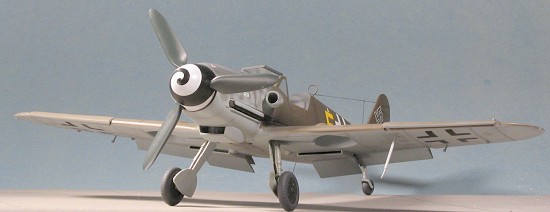 m
tabs with Vallejo red. It took two coats to get an acceptable level of
brightness. Now before you all head for your Bf-109 variants and how to
tell them apart books, I will confess that I should probably have
removed the smaller elevator trim tabs and both of the ones on the rudder,
but I didn't. I also removed the canopy masks at this time. Some came off
without a problem and some left a lot of residue, though it was easy to
remove. I should also mention that the upper canopy mask didn't want to
conform to the curve and so I had to scrape away overspray with a toothpick
before attaching the canopy.
m
tabs with Vallejo red. It took two coats to get an acceptable level of
brightness. Now before you all head for your Bf-109 variants and how to
tell them apart books, I will confess that I should probably have
removed the smaller elevator trim tabs and both of the ones on the rudder,
but I didn't. I also removed the canopy masks at this time. Some came off
without a problem and some left a lot of residue, though it was easy to
remove. I should also mention that the upper canopy mask didn't want to
conform to the curve and so I had to scrape away overspray with a toothpick
before attaching the canopy.
The prop assembly had been put together and was then pressed onto the prop shaft. The wheels were glued on, followed by the doors and I also did the small aileron counterweights. The clear bit for the Morane antenna was glued in place and this was followed by the wing tip lenses. I had to drill out the mounting for the antenna before gluing this item in place. Last steps were to attach both a long wire antenna and a short VHF antenna. This was done using stretched sprue and then painted black. The final assembly steps were to glue on the shoulder harnesses, the gun sight and finally the canopy.
| CONCLUSIONS |
Well, this one took me several weeks longer than I'd thought. Several
things caused this. One was the baseball playoffs as I stopped and watched
every game. The other was the work needed for the c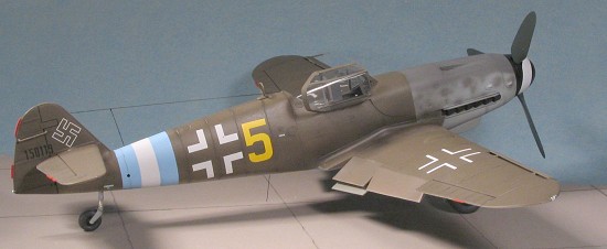 onversion.
I'm not very fast when I have to modify stuff and that took time. Another
was that I hit a bit of a slump and so wasn't as productive as usual. This
happens to all of us from time to time and is just a period we all have to
get through. Those of you with sharp eyes will notice that the kit is
missing the left wing tip light cover in some of the images. It fell off
sometime during the photo shoot. It was a miracle that I actually found it
on the floor after the pictures were taken!
onversion.
I'm not very fast when I have to modify stuff and that took time. Another
was that I hit a bit of a slump and so wasn't as productive as usual. This
happens to all of us from time to time and is just a period we all have to
get through. Those of you with sharp eyes will notice that the kit is
missing the left wing tip light cover in some of the images. It fell off
sometime during the photo shoot. It was a miracle that I actually found it
on the floor after the pictures were taken!
Overall I'm pleased with the way the conversion set worked out. It wasn't as difficult as I'd thought, but it wasn't as easy as I'd hoped! With all things like this, the work paid off and the end result is a very nice and quite interesting model. Would I do it again? Sure would, but not right away!
October 2004
#1335 in a series
Many thanks to mefor supplying the kit and to Cutting Edge for the conversion, decals and masks.
| REFERENCES |
Messerschmitt Me 109 pt 2, Michulec, AJ Press, 2002
Aero Detail #5, Messerschmitt Bf-109G, 1992
Eagle Files #3, Augsburg's Last Eagles, Green, 2000
Messerschmitt Bf-109 Recognition Manual, Fernandez-Sommerau, Classic,2004
Copyright ModelingMadness.com. All rights reserved.
If you would like your product reviewed fairly and fairly quickly, please contact the editor or see other details in the Note to Contributors.