DML 1/48 Fokker Triplane: 6th and 7th prototypes
|
KIT # |
5901 (currently OOP - July 2001) |
|
PRICE: |
$19.95 |
|
DECALS: |
See review |
|
REVIEW:: |
|
|
NOTES: |
Some modification |
Building Fokker Triplane
Experimentals
Candice=s Journey into the Brave New
World of "Kit Modifications"
|
HISTORY |
Did you ever get that feeling when you are thinking about starting a new modeling project that, wellY.you=ve seen it all? Or your dream list of models isn=t anywhere near being produced by anybody? I felt like ?I have all these kits in the closet and nothing to build!" That sounds like me when I want to go clothes shopping! Well, I had just finished a tough model (the Flashback Taube) and was a bit exhausted; I still wanted to build something, but I couldn=t decide what. So I took to my books and just started to read - browse and wait for inspiration to find me.
One book I picked up was ?Fokker Dr.1=s in Action" by Squadron/Signal publications. As I thumbed through, I noticed the various experimental versions of the Fokker triplane. The Fokker engineers didn=t just whip the final airplane out and suddenly create the famous DVII biplane fighter. What they did was tinker with the success they had with the Triplane. Then it hit me: I have never seen a model of one of these airplanes. Why was that? So as I read on over the next few days, I started to think about building one of them. So here is the saga of Candice=s journey into the less frequently traversed fields of model building, kit moddification.
- The V6 and V7 Experimental Triplanes.
 The production triplane was
renowned for great performance. Originally powered by a 110 hp Oberursel engine,
the Dr.I could out-turn just about any Allied fighter plane of the era and to
quote the famous Red Baron, it could
?climb
like monkey@.
The production triplane was
renowned for great performance. Originally powered by a 110 hp Oberursel engine,
the Dr.I could out-turn just about any Allied fighter plane of the era and to
quote the famous Red Baron, it could
?climb
like monkey@.
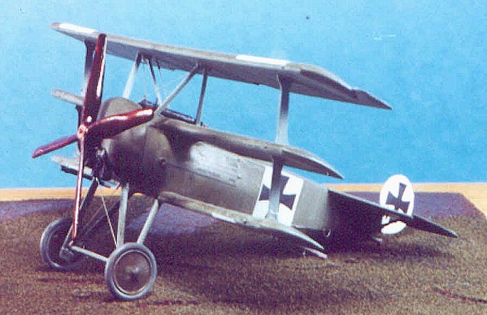
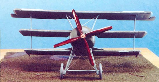
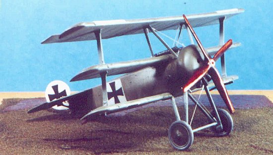
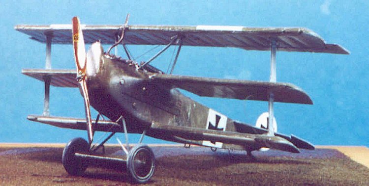
The engineers at Fokker took a great airplane and tried to make it better by adding a much larger experimental 160 hp Halske engine. This big engine needed a big 4-bladed propeller. The big prop needed additional ground clearance, so the landing gear was extended. The combination of the Halske engine with the Dr.I airframe was christened V7, factory serial number 1788.
Test pilots reported that the V7 climbed better and showed improved performance at altitude than the Dr.I, but the big engine and prop made it a difficult airplane to fly. The additional power and prop blade area made the float near the ground, even with the standard Dr.I landing gear air foil removed. The airplane was also touchy because that big prop with its increased torque made this short little fighter too tough for the average fighter pilot to handle. Besides being difficult to handle, the experimental Halske engine found not to be ready for front line service in 1917. Other engines were tried but the V7 series never made it to the production stage.
The V6 was an attempt by Fokker to alleviate another problem the Germans had during WW1 - a lack of castor oil. Rotary engines of the period were lubricated with castor oil because the oil and fuel were mixed together inside the engine. A petroleum based oil would interfere with the fuel chemistry, but since castor oil is vegetable based it would not adversely affect the fuel. (I guess oil and vegetables don=t mix.) Castor oil was difficult to obtain because it comes from castor beans, the castor beans came from the German colonies in Africa, and the Royal Navy happened to have a blockade enforced against Germany. Consequently, castor oil was a pretty scarce commodity and the entire available supply was reserved for aviation use and was in chronic short supply throughout the war.
 This is probably one reason
why WW1 German aircraft used large 6 cylinder inline engines to such a great
extent. Having a triplane that performed well with an inline engine would
alleviate the shortage of castor oil required for the war effort.
This is probably one reason
why WW1 German aircraft used large 6 cylinder inline engines to such a great
extent. Having a triplane that performed well with an inline engine would
alleviate the shortage of castor oil required for the war effort.
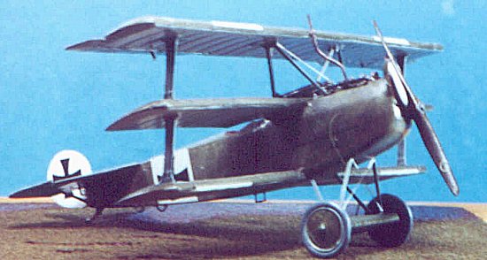
To accommodate larger engine, the triplane airframe had to be lengthened in the nose area and considerably strengthened to absorb the additional power. The added weight was accommodated by extending the wing span. The Mercedes inline also needed a radiator for cooling.
Flight testing revealed that the airplane was not very maneuverable compared to the standard triplane, most likely because it was heavy and it didn=t have the torque of the rotary engine to enable the tight turns the triplane was famous for. The pilot=s forward vision was greatly impaired because of the increased length of the nose. The V6 sported a forward mounted radiator which worked superbly while other German aircraft of the era that sported in-line engines had wing- or side-mounted radiators. In light of these test results, the V6 program was abandoned but the nose-mounted radiator was to be reborn on the famous Fokker DVII fighter of 1918.
|
The V7 Build - the Easy One! |
The bonus part of this build was that I took the first model I ever built and turned it into the V7. I stripped the paint and decals off the DML kit and figured that if I did a good job I would have a nice model. If I screwed up then all I would lose was an old junker that I never showed to anybody anyway. The defeat would be my little secret.
 The V7 is actually pretty
easy to build and since it was my first kit modification, I needed easy. My plan
was to do what the airplane designers did, design my way around the engine. A
Halske engine was purchased from Copper State Models. After fiddling around with
some ideas for a suitable cowling, I finally just took a Dr.I cowl from the kit
and modified it. To accept the much-larger engine I whittled out most of the
crown of the cowling with a modeling knife. This allowed the cowling to flex to
fit the new engine. It was a tight fit, but it fit. I used Evergreen half-round
stock and glued it over the cowling to cover up my whittled gaps and to get some
of the final rounding back. Lots of Squadron white putty was added and I sanded
to shape. I did this all with the engine in place inside the cowling, while
making sure the propeller shaft was always aligned with the shaft hole in the
cowling face. To fit the larger cowling onto the fuselage, I used .020@ Evergreen rod like a piece of molding and
just glued it to the outside forward portion of the fuselage to close any gaps
between the fuselage and the cowling. A bit of judicious putty and sanding
yielded a fit without gaps.
The V7 is actually pretty
easy to build and since it was my first kit modification, I needed easy. My plan
was to do what the airplane designers did, design my way around the engine. A
Halske engine was purchased from Copper State Models. After fiddling around with
some ideas for a suitable cowling, I finally just took a Dr.I cowl from the kit
and modified it. To accept the much-larger engine I whittled out most of the
crown of the cowling with a modeling knife. This allowed the cowling to flex to
fit the new engine. It was a tight fit, but it fit. I used Evergreen half-round
stock and glued it over the cowling to cover up my whittled gaps and to get some
of the final rounding back. Lots of Squadron white putty was added and I sanded
to shape. I did this all with the engine in place inside the cowling, while
making sure the propeller shaft was always aligned with the shaft hole in the
cowling face. To fit the larger cowling onto the fuselage, I used .020@ Evergreen rod like a piece of molding and
just glued it to the outside forward portion of the fuselage to close any gaps
between the fuselage and the cowling. A bit of judicious putty and sanding
yielded a fit without gaps.
The rest is trivial. The landing gear was made from a bamboo skewer and I figured the lengths from Dr.I vs. V7 drawings in the "in Action" book. I had a prop made by Copper State Models for the Dr.I. I tried to make my own propeller but after putting in so much work on this model, I didn=t want to waste the effort with a shoddy prop. Mount the prop, finish up the standard kit, and I have the only Fokker V7 model that I know of. My first kit modificationY..finished!
Total time was about 30 hours.
|
The V6 Build - the Hard One! |
The V7 still looks like a Fokker Triplane except for that big prop and engine cowl. The V6 is an entirely different animal. Well, nothing works like success so I started with an Aeroclub Mercedes 6-cylinder engine and planned to fit the fuselage modifications around that. A friend mine suggested I make the longer wings by using parts from two Dr1 kits and gluing them together. I just happened to have an emergency Dr.I kit sitting on the shelf. I knew it would come in handy one day!
Fuselage Modifications:
The fuselage work consisted of three parts: getting rid of the round fairing molded into the fuselage, installing the new nose with suitable engine mounts, and making the nose radiator.
The molded fairing had to be cut out of each fuselage half to just aft of the cockpit and replaced with flat sides. I hate using a razor saw just to hack out big pieces. I prefer the old sewing thread method of cutting plastic. Just take some ordinary sewing thread, hold it like dental floss, and ?saw@ it back and forth along the line to be cut. The friction ?cuts@ for you. I find this much faster for rough cuts than a saw and it also allows for cutting nice square corners.
 After cutting out the
fairing, I backed the gap with evergreen plastic stock and just glued it in
place inside the fuselage. I then used Squadron putty to fill in. Once dry I did
a dry fit of the fuselage halves and secured them with a rubber band so I could
do some fit experiments with ideas for extending the nose and accommodating the
engine. To get a reasonable nose length, I estimated that the firewall would be
just forward of the rudder pedals. After fitting the engine to about that
position I had a good idea of how much extra nose I needed. I used pieces of an
old Pfalz D.XII nose to get a good engine fit. This exercise in dry fitting also
showed that I would have to narrow the Dr1 fuselage halves a bit to mate with
the new nose. This was easy to do but also meant I had to narrow the cockpit
floor also. All in all, this was starting to look promising.
After cutting out the
fairing, I backed the gap with evergreen plastic stock and just glued it in
place inside the fuselage. I then used Squadron putty to fill in. Once dry I did
a dry fit of the fuselage halves and secured them with a rubber band so I could
do some fit experiments with ideas for extending the nose and accommodating the
engine. To get a reasonable nose length, I estimated that the firewall would be
just forward of the rudder pedals. After fitting the engine to about that
position I had a good idea of how much extra nose I needed. I used pieces of an
old Pfalz D.XII nose to get a good engine fit. This exercise in dry fitting also
showed that I would have to narrow the Dr1 fuselage halves a bit to mate with
the new nose. This was easy to do but also meant I had to narrow the cockpit
floor also. All in all, this was starting to look promising.
I installed the cockpit detail and closed the Dr.I fuselage halves, then rough sanded the newly flattened sides. Dry fitting the engine against the firewall allowed me to sand the Pfalz nose to length and the proper height. When I achieved a good engine fit that looked acceptable, I glued all the pieces together. It took about a week of work and a good amount of putty to finally get the fuselage to a shape that looked like my picture.
I made a suitable radiator by examining photos and judging what would fit and still look close to the real thing. I made the radiator from a thin piece of balsa wood and fashioned the grill work from medical tape. I then backed the wood with thin evergreen stock and covered the tape edges with thin evergreen strips. I then cut a gap into the fuselage nose to install it. A bit more putty and the fuselage was just about finished.
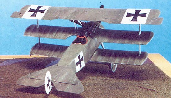
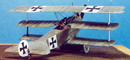
Wing Modifications:
 I planned to extend the
wing span by using parts of two kits, cutting carefully, and gluing the pieces
together. To keep things simple, I decided to add wing length by adding wing
bays cut from one wing to the other. One picture of a V6 I found is clear enough
to allow you to count the number of wing bays in the upper wing. The V6 appeared
to have two additional bays over the DML kit wing. So I needed to add two wing
bays to each wing. For the top wing I cut out the center bay of one wing and
replaced it with the center 3 bays of another wing for a net gain of two bays.
The middle wing and lower wing were each done by adding one bay to each side.
Before I glued the additional wing bays in place I made sure that the interplane
strut insertion points on the underside of each wing were equally spaced so the
interplane struts would be straight when I mounted the wings to the fuselage.
Purists will contend that I couldn=t
be sure that my V7 wing bays were the same width, etcY..but with the scarcity of resources
available and realizing that this is supposed to be FUN - onward!
I planned to extend the
wing span by using parts of two kits, cutting carefully, and gluing the pieces
together. To keep things simple, I decided to add wing length by adding wing
bays cut from one wing to the other. One picture of a V6 I found is clear enough
to allow you to count the number of wing bays in the upper wing. The V6 appeared
to have two additional bays over the DML kit wing. So I needed to add two wing
bays to each wing. For the top wing I cut out the center bay of one wing and
replaced it with the center 3 bays of another wing for a net gain of two bays.
The middle wing and lower wing were each done by adding one bay to each side.
Before I glued the additional wing bays in place I made sure that the interplane
strut insertion points on the underside of each wing were equally spaced so the
interplane struts would be straight when I mounted the wings to the fuselage.
Purists will contend that I couldn=t
be sure that my V7 wing bays were the same width, etcY..but with the scarcity of resources
available and realizing that this is supposed to be FUN - onward!
I started installing the wings with the middle wing because the DML middle wing is molded with part of the fuselage and is mounted forward of the cockpit. Some of this fuselage area must be cut out to accommodate the engine. I did this using the sewing thread trick. I installed the middle wing onto the fuselage very carefully because it can be used as guide to ensure the proper gap and angles are maintained with the lower wing. Once the middle wing was installed, I installed the lower interplane struts and used those to align and mount the lower wing.
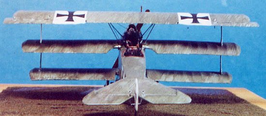
 The original V6 had a gap
between the lower wing and the fuselage. The fuselage appeared to sit on top of
the lower wing. The later V6 faired this gap over because it tended to produce
some nasty aerodynamic effects. The narrower fuselage I now had served to leave
a gap between wing root and fuselage body. I kept the gap mostly intact and just
filled the forward 1/3 with putty and smoothed it to an airfoil shape.
The original V6 had a gap
between the lower wing and the fuselage. The fuselage appeared to sit on top of
the lower wing. The later V6 faired this gap over because it tended to produce
some nasty aerodynamic effects. The narrower fuselage I now had served to leave
a gap between wing root and fuselage body. I kept the gap mostly intact and just
filled the forward 1/3 with putty and smoothed it to an airfoil shape.
The upper wing is a no-brainer to mount if the middle wing is installed with care.
From this point on the build was straightforward. The V6 photos show a pretty funky exhaust system which I made from evergreen rod, but everything is pretty simple. I finished it off with all the standard kit parts. My only additions were to add engine inspection plates made with my Waldron punch, but any old round flat stuff will do for that.
Finishing up:
I refer you to Bob Laskodi=s article in Modeling Madness on his DML Dr.I build to see a true masterpiece. I used the decals for Lt. Kempf that are supplied with the DML kit but without using the personalized markings of the pilot. My paint scheme was the same used by the prototype triplanes rather than the scheme used by the production airplanes. Tom Cleaver gives a great description on how that is done in his Modeling Madness article on Voss= Fokker F1 prototype triplane.
|
CONCLUSIONS |
All in all this was a fun little project to do and I got my feet wet exploring another area of this hobby. My modifications aren't perfect, but then again we can only do what our skills and research material allows us to do and still have FUN doing it. So, if you ever get tired of building the same old stuff that everybody else is building, I would encourage you to try a kit bash/modification project. As you can see here, you don=t have to be a model building expert to get pretty nice results.
Copyright Modelingmadness.com. All rights reserved. No reproduction in part or in whole without express permission from the editor.
If you would like your product reviewed fairly and fairly quickly, pleasecontact the editor or see other details in the Note to Contributors.