Williams Brothers 1/32 P-35
By
Mike
McLeod
 Kit:
1/32nd scale Seversky P-35/S2
Kit:
1/32nd scale Seversky P-35/S2
Kit #: Williams Brothers kit #32-135
Price: $15.00 from vendor at contest
Decals:
Scale Master # 32-135 Seversky P-35/S2. Sheet is printed in red, yellow, light
blue, dark blue, black , white, and gold. Nice quality, the clear portions were
not yellowed and remained very clear (that is invisible) once applied. The
print register was very good, almost no error.
Review and photos:
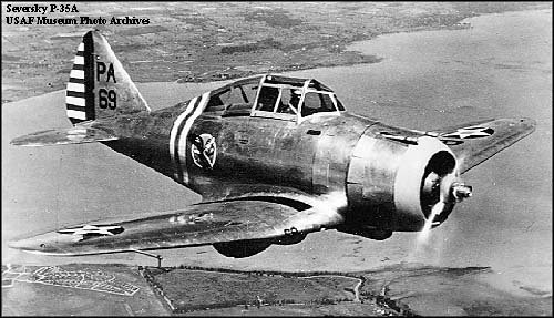
Mike McLeod, IPMS Space Coast. This kit was built to replicate the P-35 flown
by the Commanding Officer of the 27th Pursuit Squadron, 1st
Pursuit Group, Selfridge Field, MI circa 1938.
History:
In the early 30’s a pair of Russian immigrants, Alexander deSeversky and
Alexander Kartvelli teamed up in the aviation business of building Pursuit
planes in hopes of landing a lucrative US Army Air Corp contract. Their early
designs evolved into the P-35 and later the famous P-47, whose basic outline is
evident in the P-35. While aircraft designers struggled with weight and power
constraints, the Seversky design emerged as the first all-metal high performance
pursuit plane with the newly developed Pratt & Whitney R-1830 delivering almost
1,000 hp. The innovations incorporated in the P-35 included all metal semi-monocoque
construction, fuel in a “wet” wing, good streamlining (except for the heinous
main gear fairings!), and a superb wing airfoil and layout. On its debut, the
P-35 was one of the fastest aircraft in the world (281 mph) and the modified
version called the S2 Racer set may speed records (300 mph) and was faster than
any USAAC planes in service. Although it had range and speed advantages over
its rivals, it lacked in handling qualities until the flat wing was given some
dihedral on the outer wing panels.
Production P-35’s (the
first aircraft delivered to the USAAC in natural metal finish) were in service
beginning in 1937 at Wright Field, Ohio. Operational units included the 27th,
17th, and 94th Pursuit Squadrons which primarily operated
from Selfridge Field, Michigan. Units of P-35’s eventually deployed to the
Pacific Theater and were involved in early air battles with the advancing
Japanese Air Forces. Before emerging hostilities caused all US aircraft export
contracts to be nullified, some P-35’s found their way into service in Sweden as
EP-106’s. Oddly enough, and well concealed for obvious reasons, some 20 P-35’s
were sold to Japan and designated A8V-1, however they were taken from combat
duty prior to Pearl Harbor.
While the P-35 GUARDSMAN
never quite made it into the main spotlight of the times or found a spot as a
famous aircraft, it was in fact an important evolutionary step in the
development of US air power. The technology of the P-35 continued to evolve
into the P-41, P-43 LANCER, and ultimately the P-47 THUNDERBOLT. As a testament
to the design expertise of Seversky, his S-3 airfoil/wing design remained
basically unchanged from 1930 through the last service roles of the P-47N’s in
the 1950’s. His designs were capable of flying efficiently, at high sub-mach
speeds, and rugged enough to take the highest levels of punishment and continue
to fly. The P-35 was the first of this new breed of modern fighter plane and
led the way for future advancements in fighter-bomber development.
 What’s
Inside the Box: Upon opening the box
you will find several trees of medium gray styrene with a standard parts
layout. The parts for both kit options are mixed in among the trees and
numbered accordingly. The clear canopy/windscreen parts are in a separate bag
and have both Pursuit and Racing versions. The decals were missing from my box
and a call to Williams Brothers was answered by a friendly person who promptly
shipped a new set gratis…thank you! Two black rubber tires are also included
for the option if you care to risk the potential cracking and decomposition of
the tires in the future. The instruction sheets consist of an 8.5x11 exploded
view with all parts numbered and a 17.5x11 sheet with instructions on one side
and 3-views on the reverse. The 3-views are very nice and appear to match
closely the airframe outlines of photo documentation I have. The decal
placement is annotated on the 3-views.
What’s
Inside the Box: Upon opening the box
you will find several trees of medium gray styrene with a standard parts
layout. The parts for both kit options are mixed in among the trees and
numbered accordingly. The clear canopy/windscreen parts are in a separate bag
and have both Pursuit and Racing versions. The decals were missing from my box
and a call to Williams Brothers was answered by a friendly person who promptly
shipped a new set gratis…thank you! Two black rubber tires are also included
for the option if you care to risk the potential cracking and decomposition of
the tires in the future. The instruction sheets consist of an 8.5x11 exploded
view with all parts numbered and a 17.5x11 sheet with instructions on one side
and 3-views on the reverse. The 3-views are very nice and appear to match
closely the airframe outlines of photo documentation I have. The decal
placement is annotated on the 3-views.
Overall
Assessment: While this is obviously
not a high-end kit, it has all the necessary elements to allow an experienced
modeler to “take it to the limit”. While there are many minor mold
inaccuracies, most can be fixed or worked around. Other significant issues with
the kit include:
1. Plastic –
not “homogeneous” in that when scribing the tool will draw a nice, fine line and
suddenly “dig in”. In random areas the plastic is not the normal softer styrene
but a harder, more brittle styrene. In these areas the scribing tool or
scribing pin tends to make a ragged line or chip the plastic. Much care must be
used when scribing/repairing these small, random areas.
2. No alignment
pins. Mating of major assembly halves takes great care. Scribes lines cannot
go all the way to the edges. After assembly, the panel lines can be mated and
run across the seam.
3. Most of the
raised panel lines were not in the correct locations and had to be replaced with
recessed lines to allow correct orientation of the rivet lines.
4. The
horizontal stab fairings are not level and lined up side-to-side. This caused
some great difficulty when attempting to layout matching, symmetrical panel
lines prior to joining the fuselage halves. Fortunately, the stabs can be
attached even and level despite the crooked fairings.
5. Poor
definition at each control surface hinge line. The weak line was not even
suitable for a wash to bring up definition. Each hinge line had to be scribed
out and deepened to provide adequate 3-D look. Also, tail surfaces needed to be
drilled through at each hinge.
6. The cowl
flaps were cheesy at best. A simple raised outline of each set of flaps was not
adequate. As the entire cowl was removed anyway, a set of thin styrene cowl
flaps was installed with underlying linkages to provide a better look, that of a
functional machine.
7. No cockpit
detail at all to speak of, even though the box cover says “Detailed Interior”.
The only parts I was able to use were the forward bulkhead, seat, and machine
gun bodies. All other parts were scratched in. The seat was given a major
rework and detailed up including photo-etch buckles and self-adhesive strap
material. Decals were provided for the instrument/engine panel however, after
market gages and a precision punch set were employed to fabricate a much better
looking set with color and dimension.
8. Large gaps
in wing joint where outer panels meet center section. Since this model has a
flat wing/dihedral wing option, the gap will appear on the top or bottom,
depending on which wing you build. The gap was too large for putty and had to
be filled in with styrene strips to allow for subsequent panel line scribing and
riveting.
9. The landing
gear mounting holes on the wing are too far aft and had to be re-drilled about 3
mm farther forward. This was seen coming during initial parts fit and the wing
was built with a core of baked modeling clay epoxied inside to allow a
sufficient structure to bond into. This also allowed the addition of the small
ram-air inlet on the inner right leading edge.
10. The main
landing gear looked okay, but seemed too flimsy to last. New legs were
fashioned from steel music wire, brass tube, and JB Weld steel epoxy. These are
very strong and durable.
11. The
tailwheel assembly had insufficient detail and a “plate mount”. A new strut was
fashioned from styrene stock and brass tube and mounted on a correctly
positioned pivot point. The wheel and tire were cut away from the assembly and
used as a more believable tire on a music wire/JB Weld axle.
Construction
Part 1
 After studying all my
documentation and staring at the parts in the box for a while it became time to
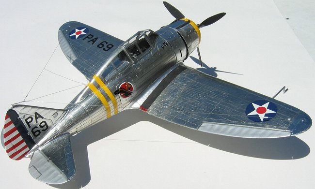
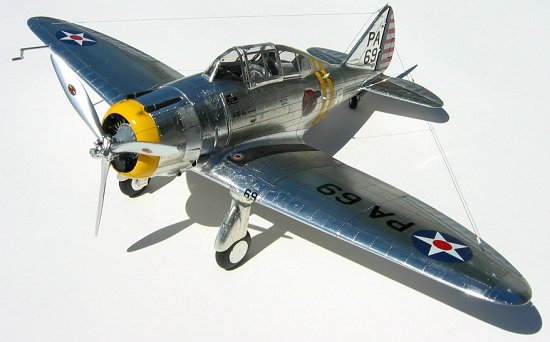
hack on some styrene. The main thrust of this project was to build a reasonable
“Natural Metal Finish” airplane, and a classic 30’s vintage Pursuit plane was an
obvious good subject. As construction began, I had some ideas of how I wanted
the model to look in my mind, but not any specific idea on how to approach
certain construction issues and methods; I would have to “wing-it”.
Consequently, much time was used in the project as I broke away from actual kit
work to experiment with a new technique, learn about different materials,
explore options, test new methods and materials, etc.
After studying all my
documentation and staring at the parts in the box for a while it became time to
hack on some styrene. The main thrust of this project was to build a reasonable
“Natural Metal Finish” airplane, and a classic 30’s vintage Pursuit plane was an
obvious good subject. As construction began, I had some ideas of how I wanted
the model to look in my mind, but not any specific idea on how to approach
certain construction issues and methods; I would have to “wing-it”.
Consequently, much time was used in the project as I broke away from actual kit
work to experiment with a new technique, learn about different materials,
explore options, test new methods and materials, etc.
This “off time” also
allowed me to take a bit of a break from the core project and return to it fresh
and ready for full effort on detail and exacting replication. To paraphrase
“the Master” Dave Platt’s Laws of Scale Modeling: “It is not about documenting
what you did build, but rather about replication of what your documentation
presents”. With that approach, a few breaks were well received. Additionally,
the somewhat scarce source data on the Seversky P-35 series of aircraft led to
some times when details were derived from documented Seversky design and
construction methods on other similar models/variants. With a suitable amount
of data and photographs I was off to the shop for some late nights and the P-35
project was under way. In the end certain assumptions and tradeoffs were made.
And not to forget another of “the Master’s” laws: “We never finish a SCALE
model, we just stop working on it…”.
ENGINE:
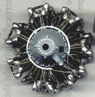 The engine detail in this
kit is very good. Crankcase is composed of three pieces with individual
cylinders directly attached. Cylinders have nice cooling fin detail although
comparison of cylinders side-by-side shows lots of variation in the shape and
size of the heads and lifter/rocker arm covers. While each cylinder has an
attach point for an intake and exhaust I elected to omit these details due to
crowding and inability to see the finished detail easily. The front row
cylinders have free standing lifter tubes running from the case to the rocker
arm covers, a nice change from the cheap looking ones molded into the side of
the cooling fins.
The engine detail in this
kit is very good. Crankcase is composed of three pieces with individual
cylinders directly attached. Cylinders have nice cooling fin detail although
comparison of cylinders side-by-side shows lots of variation in the shape and
size of the heads and lifter/rocker arm covers. While each cylinder has an
attach point for an intake and exhaust I elected to omit these details due to
crowding and inability to see the finished detail easily. The front row
cylinders have free standing lifter tubes running from the case to the rocker
arm covers, a nice change from the cheap looking ones molded into the side of
the cooling fins.
For added detail I
installed the oil cross feed tubes and drain lines (copper wire) between
cylinders and on gearbox drain. The plug wires were tricky since a thin
styrene plug wire conduit was molded into the reduction gear case. By
drilling small pairs of holes at the correct locations, I was able to feed
through short half-loops of 32-ga wire from inside the case and tack glue from
behind the conduit ring with CA. This left the neat pairs of wires to be
run up to the respective plugs on front and rear cylinder banks. Case was
painted gloss machine gray, cylinders aluminum and lightly washed with
magnesium. Other details on the engine were painted silver or gloss black
per photos and plug wires brushed with a brassy-tan color to emulate the braided
insulator covers. The engine was drilled through to accept a brass tube
which acts as a bushing for the thick music wire prop shaft / light switch, but
the brass was not glued until final assembly when prop shaft fit and alignment
were set up.
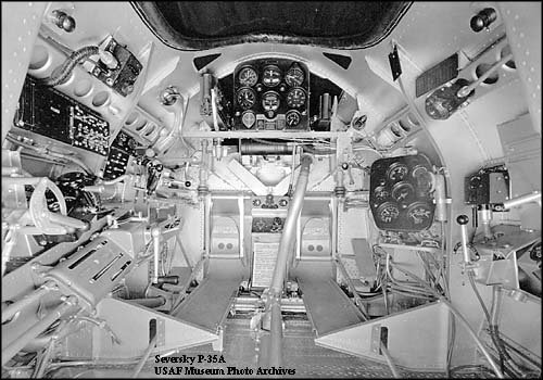
COCKPIT:
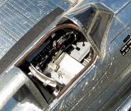
 Cockpit work began with
much planning. The only salvageable parts were the forward firewall and the
seat, both of which needed extensive work. Using photo documentation, the side walls were marked, scribed,
riveted, and a “hole-punched” beam added .
The canopy rails on the external fuselage were non-existent so some surgery was
required to hack out a groove and install a styrene I-beam to run from t
Cockpit work began with
much planning. The only salvageable parts were the forward firewall and the
seat, both of which needed extensive work. Using photo documentation, the side walls were marked, scribed,
riveted, and a “hole-punched” beam added .
The canopy rails on the external fuselage were non-existent so some surgery was
required to hack out a groove and install a styrene I-beam to run from t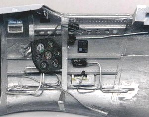 he
windscreen to the aft turtledeck. A rear cockpit bulkhead was fashioned and
riveted. Using precision punches and
instrument decals, custom main instrument and engine panels were made. The seat
was reworked to include all steel mounting tubes, seat locks, and belts/buckles
inertial reel.
he
windscreen to the aft turtledeck. A rear cockpit bulkhead was fashioned and
riveted. Using precision punches and
instrument decals, custom main instrument and engine panels were made. The seat
was reworked to include all steel mounting tubes, seat locks, and belts/buckles
inertial reel.
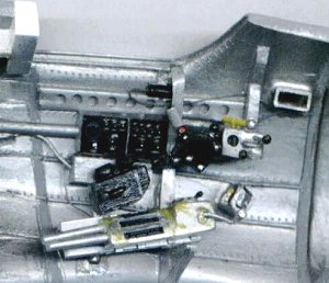
Side wall details were
manufactured (in some cased a few times before being acceptable!) and set aside
for installation. These included:
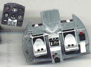 throttle quad, oil/cowl control lever box,
electrical panel, trim wheel box, gear/flap transmission, .50 cal shell ejector
chutes, rudder pedals, floor boards, wiring and tubing. The cockpit in general
was painted in aluminum metalizer, sealed with FUTURE, and washed with burnt
umber for a slightly dirty look. The top of the center wing section was prepped
at the same time with panel lines and rivets, as it is the floor of the
cockpit. The control stick pushrod and torque tube was fashioned from styrene
tube and a sewing pin, with the stick itself of music wire with JB Weld
handgrip. The side wall details were not installed until after the fuselage
halves were prepped with panel lines and rivets and the cavity vents scraped and
reworked (see “surface preparation” below). That process requires lots of
handling and any fine construction will be damaged.
throttle quad, oil/cowl control lever box,
electrical panel, trim wheel box, gear/flap transmission, .50 cal shell ejector
chutes, rudder pedals, floor boards, wiring and tubing. The cockpit in general
was painted in aluminum metalizer, sealed with FUTURE, and washed with burnt
umber for a slightly dirty look. The top of the center wing section was prepped
at the same time with panel lines and rivets, as it is the floor of the
cockpit. The control stick pushrod and torque tube was fashioned from styrene
tube and a sewing pin, with the stick itself of music wire with JB Weld
handgrip. The side wall details were not installed until after the fuselage
halves were prepped with panel lines and rivets and the cavity vents scraped and
reworked (see “surface preparation” below). That process requires lots of
handling and any fine construction will be damaged.
LANDING GEAR:
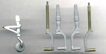 The plastic landing gear supplied in the kit
are adequate for a basic beginners build, but looked too flimsy to last…. and
who wants to EVER have a main gear bust!? Consequently, new legs were built up
by using thin steel music wire to bend and shape to hold a brass tube the same
O.D. as the I.D. of the main wheel holes (use the HARD PLASITC wheels, not the
rubber tires). The music wire was shaped and brass tube filled with JB Weld
slipped over so that main strut and axle were in same alignment as molded gear.
When cured, more brass was added to the strut, and more JB Weld swirled onto the
thin music wire. When cured the JBW was filed and sanded to nearly the shape of
the original mains. A second round of JBW was needed to get exact shape. These
gear are VERY strong!
The plastic landing gear supplied in the kit
are adequate for a basic beginners build, but looked too flimsy to last…. and
who wants to EVER have a main gear bust!? Consequently, new legs were built up
by using thin steel music wire to bend and shape to hold a brass tube the same
O.D. as the I.D. of the main wheel holes (use the HARD PLASITC wheels, not the
rubber tires). The music wire was shaped and brass tube filled with JB Weld
slipped over so that main strut and axle were in same alignment as molded gear.
When cured, more brass was added to the strut, and more JB Weld swirled onto the
thin music wire. When cured the JBW was filed and sanded to nearly the shape of
the original mains. A second round of JBW was needed to get exact shape. These
gear are VERY strong!
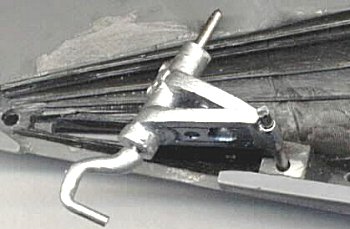 The tail wheel assembly is a single “blob”
which glues into a plate in the aft fuselage…..no thanks. The wheel was
salvaged from the unit, cleaned up, drilled and a thin brass tube axle bushing
epoxied in. A new tail strut was made from, again, thin music wire and JBW
which allowed the entire wheel to be free of the strut….nice. A styrene tail
strut was made and the inner aft fuselage prepped to show interior structure
with thin strips and rivet details.
Assemblies were painted aluminum with a touch of burnt metal, sealed with
Future, and lightly washed with black/umber mix. A small block was glued into
each fuselage half to capture the strut pivot tube when joined, and the tail
strut music wire is not glued in at all. It is held in by friction fit and a
light coat of spray post-it adhesive so it remains able to rotate 360-degrees,
yet won’t fall out, and can be removed if desired for transport. While all the
metal work
The tail wheel assembly is a single “blob”
which glues into a plate in the aft fuselage…..no thanks. The wheel was
salvaged from the unit, cleaned up, drilled and a thin brass tube axle bushing
epoxied in. A new tail strut was made from, again, thin music wire and JBW
which allowed the entire wheel to be free of the strut….nice. A styrene tail
strut was made and the inner aft fuselage prepped to show interior structure
with thin strips and rivet details.
Assemblies were painted aluminum with a touch of burnt metal, sealed with
Future, and lightly washed with black/umber mix. A small block was glued into
each fuselage half to capture the strut pivot tube when joined, and the tail
strut music wire is not glued in at all. It is held in by friction fit and a
light coat of spray post-it adhesive so it remains able to rotate 360-degrees,
yet won’t fall out, and can be removed if desired for transport. While all the
metal work 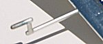 was in progress I made a pitot tube of brass since the itty-bitty plastic kit pitot tube would not last long
at all. A tight fitting brass tube was mounted in the right outer wing panel to
hold the pitot tube, yet leave it removable for transport. The brass one looks
better too.
was in progress I made a pitot tube of brass since the itty-bitty plastic kit pitot tube would not last long
at all. A tight fitting brass tube was mounted in the right outer wing panel to
hold the pitot tube, yet leave it removable for transport. The brass one looks
better too.
On to page 2
Copyright ModelingMadness.com. All rights reserved. No reproduction in part or in whole without express permission of the editor.
If you would like your product reviewed fairly and quickly, please contact
the editor or see other details in the Note to
Contributors.
Back to Main Page
Back to Reviews Page 2024