Part
2
SURFACE PREPARATION:
Now things start to get busy. The general
layout of the HUGE raised panel lines was inaccurate. The entire model was
sanded smooth and polished to a shine. Note from before, this must be done
before any assembly as the parts will be handled very roughly! The fuse halves,
wing panels, and tail surfaces were laid on my scanner and reproduced at
one-to-one so I could carefully mark and layout all panel and rivet lines.
Using many different photos from all possible angles I was able to map out the
entire structure of the plane and derive the rivet patterns. First, panel lines
were marked in soft pencil, masked with thin strips of DYMO LABEL tape, and
scribed. Panel lines (and rivet lines) were not allowed to contact any edges as
perfect alignment/continuation could not be guaranteed. After gluing halves,
panel lines are “connected”, and rivets “continued” through seams.
 Next, rivets “bumps” were
pressed into the surface using pounce wheels, or freehand pin in tight spots.
Again with the rivets, to keep lines straight they were masked with DYMO tape.
At this point, the fine “wrinkles and dimples” that appear in an aluminum skin
aircraft were applied. Using photos, the specific P-35 wrinkles & dents were
mapped out, and scraped in along specific rivet lines with a #15 scalpel blade.
The rough scrapes were finely smoothed with 600, then 1500 grit, and polished
with old style Crest toothpaste to eliminate ALL scratches. This process
eliminated many rivets, which were re-applied as needed. The fabric tail
surfaces were given a light “dimpling” between stitch lines with the scalpel and
sanded/polished. The cowl halves were sawed off at the aft cowl flap line and
set aside. Two cavity vents on each side were back-scraped to thin the plastic
(it is very thick here!) and cleaned up for a more crisp appearance. Now
attentions was turned to the control surfaces. The hinges on the P-35 showed
daylight through so each was drilled and jewelers filed appropriately. The
hinge lines themselves are weak recessed lines that will not look good even with
a wash applied. Using the various scribing tools and back edges of scalpels,
the hinges were scraped and opened up to leave a rounded control surface and a
deep recessed hinge gap. This looks much more 3-D and eliminates the need for
washes. Also, the sides of the ailerons were opened up and trim tabs made
“free”. At this point the cockpit side wall details were installed and detailed
(see “cockpit” above).
Next, rivets “bumps” were
pressed into the surface using pounce wheels, or freehand pin in tight spots.
Again with the rivets, to keep lines straight they were masked with DYMO tape.
At this point, the fine “wrinkles and dimples” that appear in an aluminum skin
aircraft were applied. Using photos, the specific P-35 wrinkles & dents were
mapped out, and scraped in along specific rivet lines with a #15 scalpel blade.
The rough scrapes were finely smoothed with 600, then 1500 grit, and polished
with old style Crest toothpaste to eliminate ALL scratches. This process
eliminated many rivets, which were re-applied as needed. The fabric tail
surfaces were given a light “dimpling” between stitch lines with the scalpel and
sanded/polished. The cowl halves were sawed off at the aft cowl flap line and
set aside. Two cavity vents on each side were back-scraped to thin the plastic
(it is very thick here!) and cleaned up for a more crisp appearance. Now
attentions was turned to the control surfaces. The hinges on the P-35 showed
daylight through so each was drilled and jewelers filed appropriately. The
hinge lines themselves are weak recessed lines that will not look good even with
a wash applied. Using the various scribing tools and back edges of scalpels,
the hinges were scraped and opened up to leave a rounded control surface and a
deep recessed hinge gap. This looks much more 3-D and eliminates the need for
washes. Also, the sides of the ailerons were opened up and trim tabs made
“free”. At this point the cockpit side wall details were installed and detailed
(see “cockpit” above).
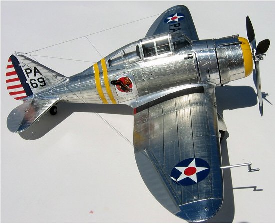
LIGHTS:
Now, I wanted this model to have some
“special” thing and operational navigation lights seemed to be the right
answer. After much research, the only viable method was to use light emitting
diodes rigged in parallel on a 12v garage door opener
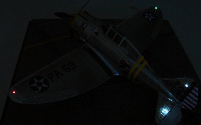 battery. Needing red, green,
and white seemed easy, but white LED’s are hard to find….and expensive. Tests
showed that the red and green LED’s were not bright enough to show through the
lens, so the extremely bright, white LED’s were used throughout. The peculiar
nav light setup on the P-35 has teardrop shaped lenses on upper/lower and
left/right surfaces. Each location uses a single LED, filed down to minimum
thickness, and epoxied in place next to the nav light. Each nav light “pair”
has a “lens”, actually a rod, of the required color that passes through the
tail/wingtip, and is shaped and polished on the end. When the white LED is
lighted, the light shines up and down through each “lens”, and generates almost
zero heat…without a bulb filament to burn out. Due to clearances, even at min
thickness, the LED’s did not fit, so each wingtip/tail had to be internally
ground down until light showed through the plastic to make room for the LED.
Each LED was color checked (they do vary a bit) and matched to a position, wires
soldered on, and tacked in place with a dab of medium CA. All part were mated
and clearance checked. When satisfactory, the thin mounting areas were
reinforced with 5-minute epoxy.
battery. Needing red, green,
and white seemed easy, but white LED’s are hard to find….and expensive. Tests
showed that the red and green LED’s were not bright enough to show through the
lens, so the extremely bright, white LED’s were used throughout. The peculiar
nav light setup on the P-35 has teardrop shaped lenses on upper/lower and
left/right surfaces. Each location uses a single LED, filed down to minimum
thickness, and epoxied in place next to the nav light. Each nav light “pair”
has a “lens”, actually a rod, of the required color that passes through the
tail/wingtip, and is shaped and polished on the end. When the white LED is
lighted, the light shines up and down through each “lens”, and generates almost
zero heat…without a bulb filament to burn out. Due to clearances, even at min
thickness, the LED’s did not fit, so each wingtip/tail had to be internally
ground down until light showed through the plastic to make room for the LED.
Each LED was color checked (they do vary a bit) and matched to a position, wires
soldered on, and tacked in place with a dab of medium CA. All part were mated
and clearance checked. When satisfactory, the thin mounting areas were
reinforced with 5-minute epoxy.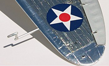
WING OUTER PANELS:
Drilling out nav light lens holes, and allowing
for wire runs into center section prepped outer wing panels. The lower aileron
has external Friese hinges and the molded “lumps” are a poor replication. Each
hinge was drilled out and a small slot left. Pairs of matching left and right
hinges (the three on each aileron are different) were filed from thing brass
stock and JB Weld epoxied into place. The excess brass/epoxy protruding into the
inner wing was ground off with a Dremel cutting wheel, and a small dot of JBW
applied to the hinge points to simulate pivot bolts and nut.
WING CENTER SECTION:
The center section of the wing is a major
structural piece on this model as it ties several sub assemblies together and
sets the alignment of the entire model. The main wheel bays are barren and I
detailed them by adding styrene strips/rivets to the inner surface of the upper
center section. To make bay walls, I formed blobs of bakable clay into each
half, carefully removed it, and baked it to harden. These clay pieces were
closely formed and when hard baked, epoxied in nicely to fill in the center wing
structure and provide a firm mounting point for the improved landing gear. As
it turned out when fitting the main struts, the mounting holes were 3 mm too far
aft and had to be re-drilled forward. Fortunately the baked clay allowed a
strong structure to work with….whew!! Holes were allowed for running the nav
light wires through to an exit point in the center of the wing below the front
firewall. The clay also allowed me to use a small tipped Dremel grinding ball
to bore out and shape the ram air inlet on the right wing leading edge which is
not molded into the kit.
ENGINE COWL:
The engine cowl halves were glued together and
the cheesy cowl flaps (just outlined with a thick raised panel line) were cut
out. Engine fit was checked and mounting hardware fashioned. The cowl must be
removable for battery access, yet tight enough that it does not look like it is
“hanging on”. By using two tight fitting concentric brass tubes glued together
and parallel, I made a self-aligning mounting post to slip the cowl on and off.
The inner brass 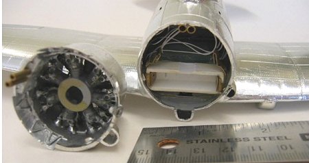 tubes are
just pegs that connect the outer pairs, which are securely glued to the fuselage
or upper cowl. These needed to be very tightly fitted as the gun exit troughs
needed t be ground/filed/sanded on each side of the mounts. New cowl flaps were
made from .010 and .005 sheet styrene with individual linkages behind each
door. Exhaust pipes were drilled out and replaced with thin walled brass for a
crisp look. Engine fit was adjusted and panel lines/rivets were applied to the
cowl, making sure patterns aligned with the fuselage. Cowl fit was adjusted to
ensure mating seam was minimal and would fade into surface like a panel line.
The forward exposed gun barrels were made at this time and exit trough alignment
checked. Thin wall brass tube was glued into the cowl to neatly accept the gun
barrels during final assembly. The somewhat complex rivet patterns on the cowl
were pin-stick applied. The larger cowl fasteners were made with a pin vise and
small bit by just “starting” the bit to make a small circular divot that has
relief and is larger than a rivet.
tubes are
just pegs that connect the outer pairs, which are securely glued to the fuselage
or upper cowl. These needed to be very tightly fitted as the gun exit troughs
needed t be ground/filed/sanded on each side of the mounts. New cowl flaps were
made from .010 and .005 sheet styrene with individual linkages behind each
door. Exhaust pipes were drilled out and replaced with thin walled brass for a
crisp look. Engine fit was adjusted and panel lines/rivets were applied to the
cowl, making sure patterns aligned with the fuselage. Cowl fit was adjusted to
ensure mating seam was minimal and would fade into surface like a panel line.
The forward exposed gun barrels were made at this time and exit trough alignment
checked. Thin wall brass tube was glued into the cowl to neatly accept the gun
barrels during final assembly. The somewhat complex rivet patterns on the cowl
were pin-stick applied. The larger cowl fasteners were made with a pin vise and
small bit by just “starting” the bit to make a small circular divot that has
relief and is larger than a rivet.
PROPELLER AND HUB:
This kit has a nice prop design, but the molds
left huge dimples and sinks in each blade. The hub has the basic shapes correct
but the long, stretched up pillars simulating the fly-weights look terrible.
The massive pillars were cut off clean down to the hub, and a small groove
etched in. Scrap brass fret and styrene rod was used to make good looking fly-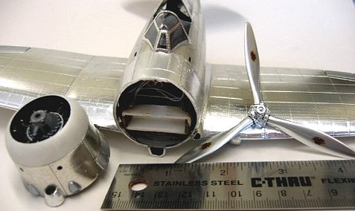 weights.
The sink holes in the blades were filled in with medium CA and shaved with a
scalpel, sanded with 600/1500 repeatedly until corrected. A thin aluminum tube
ring was made to give the hub actuator a more 3-d look. Brass tube of the same
size as the engine core piece was used to make a bushing which was fitted into
the rear of the hub assembly to accept the steel music wire prop shaft without
damaging the plastic hub assembly. The blades were attached on a jig for
alignment and orienting in one planed of rotation. The entire assembly was
polished with Crest and washed, painted with a nice “wet” finish of gloss black
Model Master enamel, and set aside to cure for 5 days. The hub was finished
with chrome ALCLAD II and the blades polished aluminum ALCLAD II. Decals went
on nicely and the whole unit was final coated with Tamiya X-22 clear acrylic.
weights.
The sink holes in the blades were filled in with medium CA and shaved with a
scalpel, sanded with 600/1500 repeatedly until corrected. A thin aluminum tube
ring was made to give the hub actuator a more 3-d look. Brass tube of the same
size as the engine core piece was used to make a bushing which was fitted into
the rear of the hub assembly to accept the steel music wire prop shaft without
damaging the plastic hub assembly. The blades were attached on a jig for
alignment and orienting in one planed of rotation. The entire assembly was
polished with Crest and washed, painted with a nice “wet” finish of gloss black
Model Master enamel, and set aside to cure for 5 days. The hub was finished
with chrome ALCLAD II and the blades polished aluminum ALCLAD II. Decals went
on nicely and the whole unit was final coated with Tamiya X-22 clear acrylic.
CANOPY:
The clear canopy parts on this model are nice.
They are packaged in a separate bag and were in good condition. Their fit is
excellent and little sanding or rework was required. I cleaned up the pieces,
scraped and pre-fit them, and dipped them in Future. Using a pin-stick, rivets
were applied as required on the inner surfaces of each piece. Thin strips of
Bare Metal Foil were applied and burnished on the inner surfaces. With the
pin-stick again, rivets were applied to the outside and “matched” to each rivet
on the inner surface. No foil was applied as this would be done in final outer
covering. Points where the pieces would touch the fuselage and mate with glue
were checked free of any foil. For the sliding canopy portion, two pieces of
scrap fret were used to make the skirt which covers the canopy rail, and thin
wire used to make the left side canopy outer latch handle.
On to the Final Part
Copyright ModelingMadness.com. All rights reserved. No reproduction in part or in whole without express permission from the editor.
Back to Main Page
Back to Reviews Page