| KIT #: | RM 5012 |
| PRICE: | $85.00 |
| DECALS: | No decals |
| REVIEWER: | Donald Zhou |
| HISTORY |
Place: Stalingrad, 1942.
In the yearlong slog of a bloodbath that followed, the Wehrmacht were bled nearly to its knees with the loss of over 300,000 men, nearly 1 million casualties and too many machines and materials to count. What the Wehrmacht found out mostly was that a heavy machine was needed to breach city blocks and able to destroy blocks at a time to root out defenders and eliminate hidden threats. At the time, the Sturmgeschutz III and the Panzer IV D were used for infantry support and these were found to be generally lacking and 14 Stug III’s and other such similar vehicles were lost in Stalingrad. Afterwards, a crash program was launched to produce an assault gun that could support infantry while under good armor protection. The first of these was the Sturmpanzer IV Brummbar, or “Grizzly Bear”. Mounting the same basic weapon as the Panzer IV D but greatly enlarged to 150mm, but with a fixed casemate with greater armor protection, it was designed specifically for this role. However, it was felt that an even heavier vehicle, mounting a much heavier gun that could shatter city blocks at a time, under much thicker armor was needed. To this end, it was quickly decided to take a Tiger I chassis, and then mounting a 280mm weapon on it. However, when that weapon was not available, the Wehrmacht quickly adapted a Kreigsmarine 380mm rocket propelled weapon, based on a depth charge throwing gun instead.
The design was very much like the Sturmpanzer IV in which the entire upper
front of the vehicle was removed, including the upper deck and turret. Instead,
a heavy frontal casemate like shell was added to contain both the fighting,
driving and the main weapon and 14 380mm shells. All of this was fixed upon the
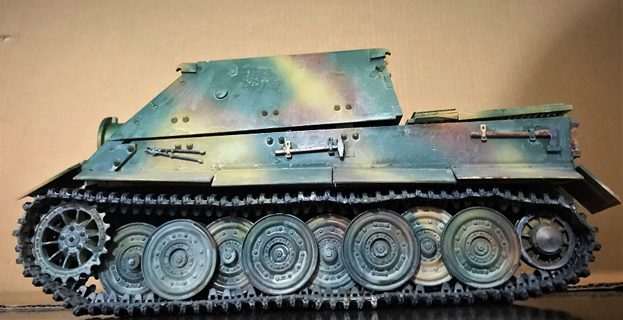
lower hull of the late Tiger I with the steel road wheels. The Tiger’s
transmission, running gears and engine are kept. Due to this, the Sturmtiger is
much shorter length wise than the original Tiger since it did not have a long
barreled cannon and not as tall due to lack of the turret. However, its weight
is more comparable to the King Tiger! At a full up weight of some 75 tons (68
tonnes), its one ton shy of a fully loaded KT! The reason isn’t just its massive
380mm shells, which 14 can be carried (even though one have to be in the breech
and one on the loading tray. Safe to say, most crews didn’t do this), with each
one weighting in at a massive 896lbs, but also its armor. The Germans felt under
urban conditions, heavy armor was needed. To this end, the Sturmtiger was
designed to carry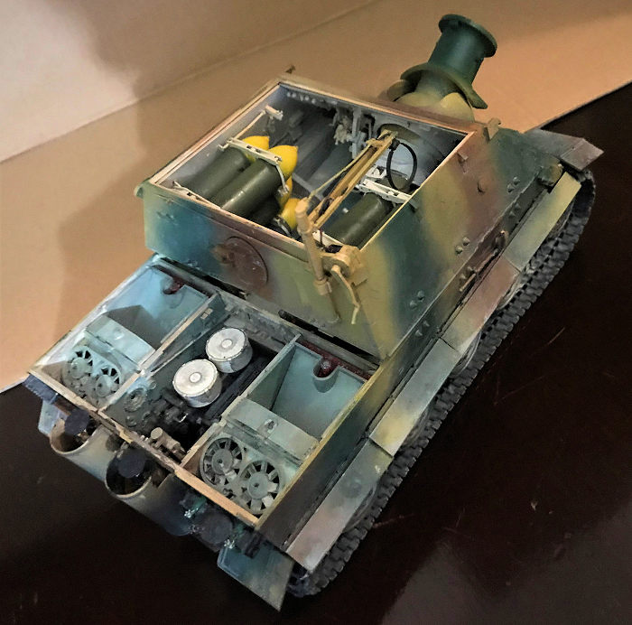 a frontal armor of 150mm at the front, 82mm at the sides and
rear, and 62mm everywhere else except the hull bottom, which is 28mm. This added
all up equal to a vehicle that’s approaching a super heavy weight!
a frontal armor of 150mm at the front, 82mm at the sides and
rear, and 62mm everywhere else except the hull bottom, which is 28mm. This added
all up equal to a vehicle that’s approaching a super heavy weight!
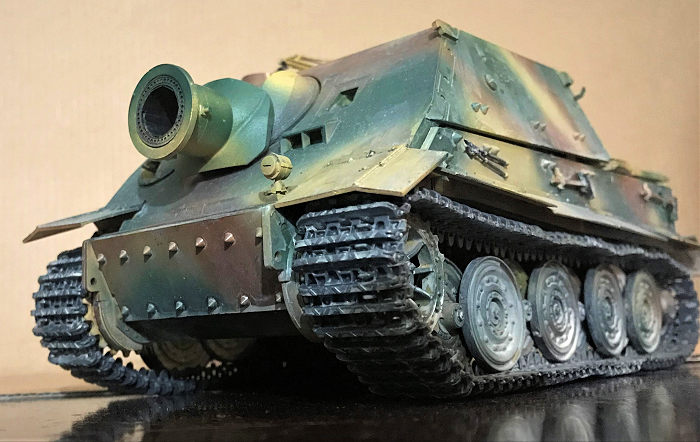
Meanwhile, its main armament, the RW 61 rocket launcher could launch an 896lbs rocket shell for up to 6000M/yards. The shell has several versions. The two most important ones are the high explosive, which was used to knock down entire city blocks, and a shape-charged version, used to plink fortifications. This version can penetrate up to 8.2 ft. of solid concrete. However, initially, the weapon ran into some problems. Namely, no rocket fumes or exhaust can be allowed to leak into the fighting compartment….For all the obvious reasons but also the exhaust fumes are deadly if breathed in! However, the exhaust gases are not allowed to stay too long in the barrel and breech either since the buildup of pressure would eventually crack both vessels. This is why the barrel has a ring of ventilation holes around it so that spent rocket exhaust gases can be quickly vented out, giving the barrel somewhat of a pepper shaker appearance. It was intended for the Sturmtiger to operate with a follow on ammunition carrier since it itself can only carry 14 rounds of ammo. The ammo carrier was based on the Tiger too but only 1 was produced before the war drew to a close. Secondary armaments included a bow mounted MG34 machine gun and a mortar to engage infantry and high up and close in targets.
When it finally entered production however, Germany was well on its way to being defeated. So the vehicle was hardly used in its intended role. The only real action it saw was the Warsaw Uprising in which two vehicles were used to root out the Polish resistance fighters.
The only other real action the vehicle saw was during the Battle of the Bulge, where 7 vehicles participated.
The third and final action was Battle of Remagen, in which 7 Sturmtigers tried to destroy the bridge itself with its main weapon but quickly found out they did not have the accuracy to do so. It was here that one chanced upon a village full of Shermans and fired a shell at it before retreating. The end result was the 380mm round flattened the village and knocked out all of the Shermans, wounding and killing many of their crews. Other than that, the war closed out before the Sturmtiger can see any other action. Only 17 Sturmtigers were produced before it was all over. Today, two of them still exist, including one at Kubinka Tank Museum, Russia. The other is at Deutches Panzermuseum, Munster. This vehicle is a captured example and was shipped to the States for tests before it was put on display at the Aberdeen Proving Grounds Tank Museum before the tanks were then transferred to Fort Bennings as the new tank museum and the rest scattered to the six winds. This surviving Sturmtiger was loaned to the Germans, where it still resides today.
| THE KIT |
See my preview here. Whatever I said is still true… Yeah, you might have guessed it, the reason took so long was not only to get a few projects off of the “Waiting to be completed line” done, but also those stupid pesky multiple piece single piece tracks.
Other than that, it’s just a long slog of patience and jump here and there due to the interior painting required.
| CONSTRUCTION |
 Construction strangely, begin with the casemate. The first are some details,
including the vent opening shutter assembly and the ammo holder straps. Notice
that one of the strap on each holder is photo etch so get ready to bend the tip
to scale. Becareful with the aiming device as there are a lot of small parts on
all of them. The rear wall details are also made before the straps are assembled
onto the left and right walls. Again, they are designed to move so becareful
with the pins that hold them in place. Use superglue if you have to. Yes, as may
have guessed, everything is done in subassemblies first before they are all
cemented together.
Construction strangely, begin with the casemate. The first are some details,
including the vent opening shutter assembly and the ammo holder straps. Notice
that one of the strap on each holder is photo etch so get ready to bend the tip
to scale. Becareful with the aiming device as there are a lot of small parts on
all of them. The rear wall details are also made before the straps are assembled
onto the left and right walls. Again, they are designed to move so becareful
with the pins that hold them in place. Use superglue if you have to. Yes, as may
have guessed, everything is done in subassemblies first before they are all
cemented together.
The front casemate is next, spare machine gun barrels and all the details assembled earlier are now added before the walls are inserted into the main casemate assembly. Take your time and don’t knock anything loose, especially with the main barrel elevation wheel.
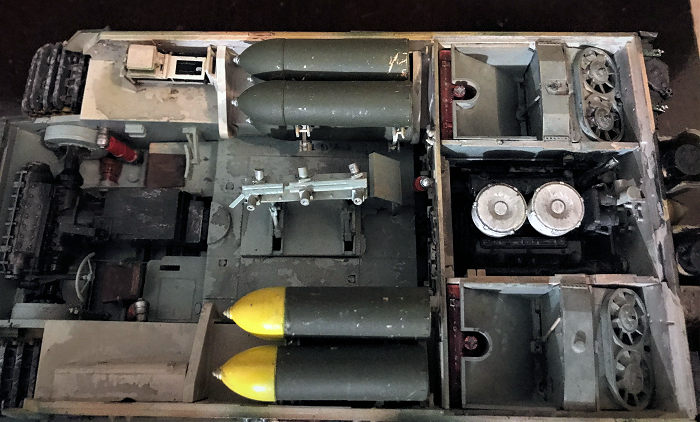
The next major subassembly is the main rocket launcher barrel and its breech. The 14 shells are also assembled. Now, as mentioned earlier, the only way a Sturmtiger can hold 14 shells if one is loaded into the breech and one is held on the loading dolly. Safe to say, most crews did not like this so 12 is the normal loadout. Now, the color call out for all the rounds is Field Grey. But safe to say, the vehicle usually carried two types of shells, the normal high explosive one, and a shape charged. To denote this distinction, I colored six of shell noses yellow to denote that they are high explosives. Don’t know the accuracy since I couldn’t find any photos but normally, all German high explosive shells had their noses colored in yellow to denote this fact so it’s pretty logical to assume this was the case for the Sturmtiger also.
Before the main cannon can begin, make a decision on what “collar” to use. This is the huge armor piece that’s hung back behind the barrel, just in front of the elevation ball assembly to not only prevent enemy projectiles from penetrating or getting stuck in the ball joint, but also deflect the smoke and blast from the rocket projectile away from the vehicle. Two types of “collars” are offered. I used what looks like the type of collar used on the Sturmtiger that’s now in the Deutch’s Panzer Museum in Munster. At this point, several metal blockers are assembled onto the barrel end itself. Two large ones that go on the top and bottom, and two smaller ones that go on the left and right. The instructions give out the distance in mm on where to cement them but who the heck have a ruler that has 0.3mm on it?!?!?!?!? No one that is! So to save me the headache, I took out the barrel deflector ring, again, there are two type, the regular round one, and a “pincer” type one. Again, I chose the regular round type and carefully put it on the end of the barrel. The top and bottom large blockers goes right behind the barrel ring so I marked the spots with a pencil and then took it off the ring and cemented the two blockers. With the large ones in place, it’s easy to judge where the smaller ones are so these were also cemented on before the nose ring was placed on again. The end of the barrel was completed with the pepper shaker like vent holes. Three types are offered. Again, I picked what looked like the one closest to the Sturmtiger at the Panzer museum.
 The barrel is then completed with the massive ball joint that allows the
rocket launcher to elevate and swing side to side. Make sure you only cement
parts C58 on the edge only since the stubs that are attached to them allows the
barrels to swing side to side. Finally, parts A45 and A46 traps them and the
barrel in place and allow the whole entire assembly to swing up and down. Now, a
lot of tiniee photo etch bolt heads, S11 are assembled onto the barrel. After
dry assemble the barrel into its housing, guess what? You can barely see these
so I canned them! Be sure you insert the two poly caps onto the elevation studs
so they can move properly. Afterwards, the whole entire assembly is trapped
between part A51 with the “collar” attached to the barrel to complete the
assembly. Just don’t miss the ball mounted machine gun mount besides it.
The barrel is then completed with the massive ball joint that allows the
rocket launcher to elevate and swing side to side. Make sure you only cement
parts C58 on the edge only since the stubs that are attached to them allows the
barrels to swing side to side. Finally, parts A45 and A46 traps them and the
barrel in place and allow the whole entire assembly to swing up and down. Now, a
lot of tiniee photo etch bolt heads, S11 are assembled onto the barrel. After
dry assemble the barrel into its housing, guess what? You can barely see these
so I canned them! Be sure you insert the two poly caps onto the elevation studs
so they can move properly. Afterwards, the whole entire assembly is trapped
between part A51 with the “collar” attached to the barrel to complete the
assembly. Just don’t miss the ball mounted machine gun mount besides it.
I skipped the ball mounted MG34 machine gun till final assembly. To complete this massive launcher, the breech assembly is next. Some small parts so be careful, the breech should be able to move afterwards. Becareful assembling it onto the barrel since you do not want to cement to leak onto the ball joint. This complete the main casemate. I then took it to the paint shop to spray it with light grey.
The lower hull begin with the drive train assembly. This begins with the torsion bar holders. They are all in photo etch so take you time. You can be little messy since the floor boards will go on top most of them but still, be sure everything fits or you’ll have problems later. I sprayed the torsion bar themselves as gunmetal before inserting them into their holes. They should be operable if you just cement the tips in. Once the arms and drive sprocket holders are on, the main interior can begin.
The interior begins with the radios. Since the front is now sloped, the radios are moved to the radio operator’s right side. I just assembled the holders, and left the radios until later cause they are black. The seat and the shock absorbers are also made at this time
The driver seat and the front covering are made next. Be sure not to lose the various petals to the carpet monster. The front covering has the driver’s bezels on it. Leave this part for now. I tried to put it on but it kept on snapping off due to the handling! The whole entire front is complete with the transmission, which I painted gunmetal. This is pretty big assembly so take your time. Afterward, the whole entire thing is inserted to the front of the vehicle. Notice the top covering, it’s pretty tight between the hull side and front so do not cement it on if you want. I didn’t so I can remove it to show off the interior.
The engine and the transfer drive rods are next. You do not need to paint the drive rods cause you’ll see why later. I again, painted the engine gunmetal except the two air filters, which are white. It’s here that I encountered a problem. Namely, the exhaust pipes do not reach to the rear wall, forcing me to use some stretched sprue to fix this. No biggie.
 The rear wall is now assembled and it, along with the engine is placed into
the correct space. I did not do this cause of course, you need to paint the bays
first. To this end, I had to jump slightly ahead, and added the main floor board
with the loading dolly and the side support that holds the gas tanks and
radiators. I sprayed the walls and top sponsoons with light grey, and the floor
boards RLM Schwarzegrau 003. Same with the radiators and the armor coverings
that covers the gas tanks. The gas tank themselves are rotbrun. After the paint
was dried, I added each subassemblies to the correct place. This was the same as
the rear wall. This was sprayed light grey on the inside. I skipped pioneer
tools on the outside but added the exhaust pipes. Careful with the support rods.
These are tinnie and you will lose them if not careful. Afterwards, it’s
assembled to the rear of the vehicle to cover it up.
The rear wall is now assembled and it, along with the engine is placed into
the correct space. I did not do this cause of course, you need to paint the bays
first. To this end, I had to jump slightly ahead, and added the main floor board
with the loading dolly and the side support that holds the gas tanks and
radiators. I sprayed the walls and top sponsoons with light grey, and the floor
boards RLM Schwarzegrau 003. Same with the radiators and the armor coverings
that covers the gas tanks. The gas tank themselves are rotbrun. After the paint
was dried, I added each subassemblies to the correct place. This was the same as
the rear wall. This was sprayed light grey on the inside. I skipped pioneer
tools on the outside but added the exhaust pipes. Careful with the support rods.
These are tinnie and you will lose them if not careful. Afterwards, it’s
assembled to the rear of the vehicle to cover it up.
Again, I skipped the pioneer tools until later. The wheels are next. Late version of the Tiger I was easier since the Germans removed 16 wheels from the collection to “only“ 32 wheels in total, 16 wheels per side but still complex. Start with the inside wheels for the even arms, 2, 4, 6, 8. Then add the sandwiched single wheels on the odd arms, 1, 3, 5, 7 before attaching the outer wheels for the even arms. Now, these wheels can be made to move so study the instructions carefully. The whole entire thing is finished with the drive sprockets and idler wheels.
The rear engine deck is next. There are some photo etch screens so use superglue. Quite a few parts here so take your time. Now, I didn’t cement on the engine deck to once again, able to remove it to display the inside.
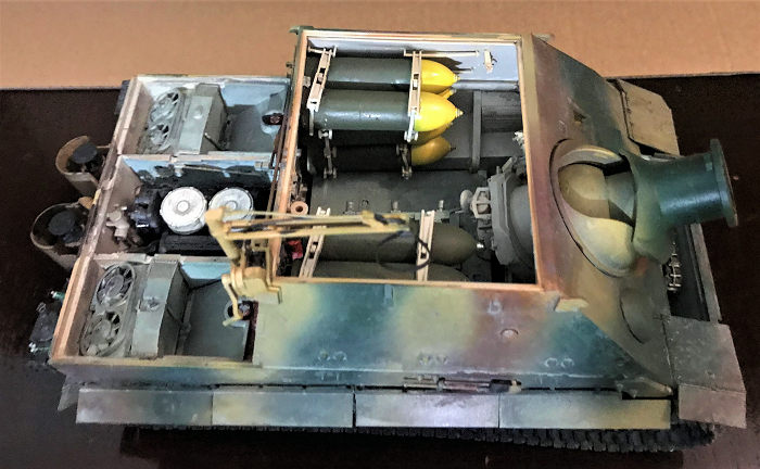
A major assembly is now made. You have to get all 12 shells onto their holding cradles. There is a way about this so follow the instructions carefully. Lift up the first wall mount holders on the hull and insert the bottom most shells. Now superglue those arms down, do be very careful with the inner most arms. Once that middle set of arms are tightly on the shells, cement the next four shells on those holders/cradles. Now, carefully insert the casemate with bottom most cradle/holder arms onto the second row of shells. I did not cement or superglue these in place since I wanted the casemate to be removable. Because of this, I jabbed the cradles tightly in place onto the shells before carefully cementing the third row of shells in place on here. After the cement was dried, I carefully lowered the top most cradle/holder in places, carefully inserting the inner most straps through and superglued the top cradles on. This way, I can remove the casemate any time I want. It’s a major hassle but unavoidable. I saved the two extra shells as show and display later.
The roof assembly is next. The interior mainly deals with the vent fans and the main moving dolly that’s on rails. This dolly is used to load the massive 800lbs shell. The crews will pull out chains and cables from the floor boards, attach chains and cables onto this dolly and then swing them onto the rear end of the shell. The front is held in place with more chains and cables onto two hooks at the front. Carefully now, the pulley is used to pull the rear off of its cradle and onto the loading tray. Once in place, the front is also swung onto the tray before a huge hand crank is used to literally crank a shell into the breech.
Finally, the vehicle is complete with the rear hatch, the side skirts, the external loading crane and tracks. The side skirt I shoulda saved for later cause I kept on snapping them off due to the painting and handling. But I do want to paint them together. Now, the loading crane, the cable and the holding strap are copper wire and photo etch so saved them for final assembly, same with the tracks. To the paint shop we go….FINALLY!!!!!!!!!!
| COLORS & MARKINGS |
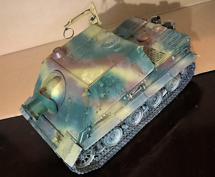
 There are no markings. Some generic iron crosses are included but the vehicle
I’m making is devoid of markings. It’s in a three tone camo of dark yellow, red
brown and dark green. I free handed it since there was no one official scheme
and German crews painted their vehicles every which way.
There are no markings. Some generic iron crosses are included but the vehicle
I’m making is devoid of markings. It’s in a three tone camo of dark yellow, red
brown and dark green. I free handed it since there was no one official scheme
and German crews painted their vehicles every which way.
The first to go on is dark yellow, followed with red brown and then dark green. I had to becareful since the rear deck was not cemented on there are also a lot of smaller pieces that I didn’t want to knock off. Weathering was my usual way. However, since only 17 of these vehicles were ever built and most didn’t see action, I kept weathering down to a minimum. Just one coat of jet black and one coat of beach comber beige, thicker on the drive gears than on top. After that, final assembly can begin.
| FINAL CONSTRUCTION |
The first major one are the tracks, these are a serious monotonous headache since the instruction called for 96 per side, which turned out to be one less, and you have to insert two pins on each side, and two guide teeth on the top. To help you with this, RMF gave you a jig. What happen is, you snap off four tracks, place them on the jig, then snap off four track pins by the pour gate (which contains four pins anyways), insert the pins on each side before snapping off of the guide teeth, also by the pour gate, and cement then onto the tracks. I first did all 96 links of tracks. This turned out to be quite easy. I was able to do it in four days for all 192 tracks. The next part wasn’t. I then snapped off each individual guide teeth and monotonously cemented them on, one by one, onto the tracks. Safe to say, not all of the teeth took hold. They broke off when I went to break off the pour gate and had to use superglue. All in all, it took me almost a week to get this done but done they did and I weathered them in the usual way.
After that, it’s just A LOT of fiddly bits. The first to go is the ball mounted machine gun. RFM made a very detailed assembly with a lot of small part. The gun itself is in two piece…Why..Just why……Then the aiming head piece, the scope and the trigger are all cemented onto one another. Now, most companies stop here but not RFM. Now, a bottom piece is added, with two ammo pouches on each side before they are attached to the bottom of the gun with an ammo belt! It’s here I finally realized how these things worked! The trigger is separated from the gun so the radio operator do not have to deal with the recoil. The ammo is fed from the left. The pouch on the right is empty to catch all the spent casings so the crew don’t have a headache finding them on the bottom, in between the torsion bars! Clever design!
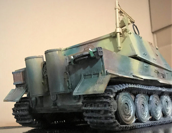
 After that, all the exterior pioneer tools are assembled. These include the
wooden lifter block and the 45 tons lift jack on the rear, and the hammer,
shovel, and ax on the sides. Now, a choice is given. You can bend the straps
from given photo-etch or plastic ones with the straps molded on are also given.
I used the plastic ones. Now, purist will scream, “WAHHHHH!!! NO DETAIL!!!” I
just slap back with “By this time, I just want this project to end and save me
the headache so Sue ME!!!!” Yeah, these days, easiness win any day of the week!
After that, all the exterior pioneer tools are assembled. These include the
wooden lifter block and the 45 tons lift jack on the rear, and the hammer,
shovel, and ax on the sides. Now, a choice is given. You can bend the straps
from given photo-etch or plastic ones with the straps molded on are also given.
I used the plastic ones. Now, purist will scream, “WAHHHHH!!! NO DETAIL!!!” I
just slap back with “By this time, I just want this project to end and save me
the headache so Sue ME!!!!” Yeah, these days, easiness win any day of the week!
Next, the clear pieces. There are some clear lights to be assembled into the interior and the driver’s periscopes. I almost lost one to the carpet monster so becareful!
Finally, this long slog is over with the exterior winch. The first is the copper wire doubling as the lifting cable…..Whoever thought this was a good idea need to be taken out back and shot! The copper wire had very little flexibility. I had to break apart the top of the crane to get it to go between the two supports. After that, getting it to go around the cable winch holder was a PITA and a half! I actually broke the copper wire in half. Thank goodness the holder wall piece, A23 covered up this mess! All in all, this took me over 3 hours to make! That should give you a good idea the struggle I had! Why couldn’t RFM just use flexible nylon cable is beyond me!
Finally finally finally………..The photo etch shell strap was made. This was far easier. I used one of the spent shell, and wrapped the strap around it and bend attachment point to place. This was cemented onto the tip of the copper wire and painted gunmetal black……………………………………..PROJECT FINALLY DONEEEEEEEEEEEEEEEEEEEEEEEEEEEEEEEEEEEEE!!!!!!!!!!!!!!!!!!!!!!!!!!!!!!!!!!! WHHHHHHHHHHHHHHHOOOOOOOOPPPPPPPIIIIIIIIIEEEEEEEEEEEEE!!!!!!!!!!!!!!!!!! Open up my dad’s Chinese Mao Tai Rocket Fuel, pour a shot and knocked it down…………………………………………
WOOOOOOOOOOOOOOWAAAAAAAAAAAHHHHHHHHHHHASDFADGFC BXVCBSERTRYSHFDHTYHGR!!!!!!!!!!!!!!!!! JEEEBUS!!!!!! Thought I HATED this pure liquefied POWERDER ALUMINIUM rocket fuel!!!!!!!
| CONCLUSIONS |
Squirming and dizzy walking through my rocket fuel induced dizzy haze….Anyways, yeah, took me a huge long haul to get here…But it’s done. The bonus is, it’s probably green enough to be placed into my club’s next year…HOPEFULLY next year’s IPMS model show…..As you may guessed, due to this year massive mess of a virus thing, this year’s show was canceled (and this year was supposedly be “get your project off of the shelf of doom” contest….Which this project also qualifies). It’s a wonderful kit….But the complexity of the interior, the amount of photo etch, the insane track assembly will put of a good number of people. I don’t blame them. This thing takes patience and some modeling skills, not as much as my major slog of project that was the 1/16 Kingtiger, but will still give you some pause. RFM has taken this kit, removed the interior and has come out with an exterior kit only of the Sturmtiger. However, that kit costs $60…..Consider I paid $85 for this, the savings may not be for some people….However, if you want to save yourself the headaches, then perhaps you can find the Tamiya and AFV Club ones for cheaps on eBay. However, if you want a definitive show stopper, then this kit definitely fit that bill!
15 March 2021
Copyright ModelingMadness.com. All rights reserved.
If you would like your product reviewed fairly and fairly quickly, please contact the editor or see other details in the Note to Contributors.
Back to the Main Page Back to the Review Index Page Back to the Previews Index Page