ESCI 1/48 AD-4W/AD-6 Skyraider
| KIT #: | 4046/4040 |
| PRICE: | $5.00 each on sale in 1980 |
| DECALS: | Two/Three options |
| REVIEWER: | Torben Plesberg |
| NOTES: | Converted to Skyraider Target Tugs |
| HISTORY |
For a more general history of the development of the Skyraider, see here. I shall only deal with the Swedish target tugs.
In the
beginning of the sixties Svensk Flygtjänst (SF) was a bit short of suitable
target tugs. The firm had operated target tug aircraft since 1939 using a single
Junkers W. 33. In 1945 SF acquired 13 Fiat CR 42 Falcos from Flygvapnet, when
this type was finally phased out. These aircraft were hardly a great success,
since only two years later they were replaced by 8 Miles Martinet TT, which were
purchased from the surplus stocks of the RAF. These planes mainly made of wood
showed some glue failures, and were grounded and later scrapped. The replacement
aircraft was another British aircraft assembled without glue: the Fairey Firefly
Mk I. 16 aircraft were purchased from the surplus stocks of the RAF. In 1959 a
 further
three aircraft were acquired from the Royal Danish Air Force, which had just put
the type out of service. The Danish aircraft were never registered in Sweden,
the aircraft should only be used for spares. A couple of Gloster Meteor T Mk. 7
were operated as high speed target tugs, and they were supplemented by four
Danish Meteor TT 20 in 1962.
further
three aircraft were acquired from the Royal Danish Air Force, which had just put
the type out of service. The Danish aircraft were never registered in Sweden,
the aircraft should only be used for spares. A couple of Gloster Meteor T Mk. 7
were operated as high speed target tugs, and they were supplemented by four
Danish Meteor TT 20 in 1962.
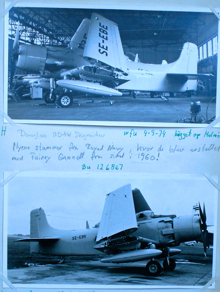
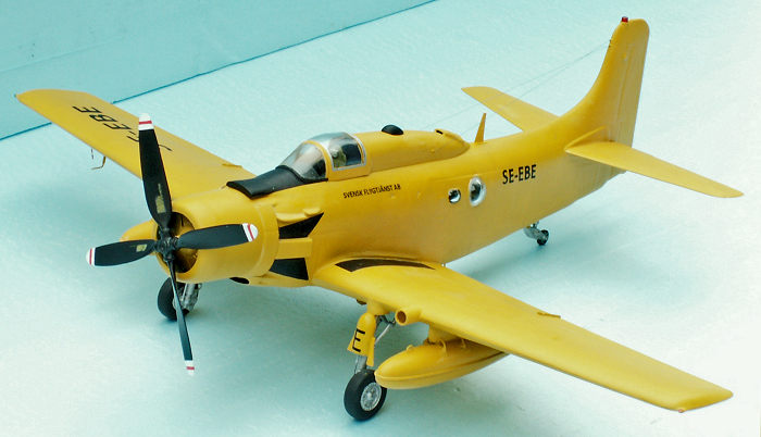
In 1961 13 Douglas Skyraiders AEW 1 were purchased from the surplus stocks of the Royal Navy. The Fairey Gannet was put into service for the AEW task, and the Skyraiders were not needed any more. However, the Skyraiders had to be converted to TTs, and this work was done by Scottish Aviation Ltd. at Prestwick. The job included removal of the radar dome, all armament and armour plates, and the twin fins of the tail planes. The radar observer’s cabin was changed into the target operator’s room complete with a winch and other equipment for target towing. The aircraft got their new color, a bright yellow color, close to “ RAF trainer yellow”, and flown to Sweden during 1962-63, where they got their civil registrations: SE-EBA to SE-EBL (not EBJ!)
Twelve of the thirteen planes were refurbished and converted to target tugs by Scottish Aviation. The thirteenth plane, however, was not converted, but shipped to Sweden, where it was stored at Bulltofta. This plane was taken from storage in 1969 after the loss of the SE-EBH in 1968 at Luleå. The spare aircraft was converted in the workshop of SF at Bulltofta, Malmö. The spare aircraft SE-EBN did not have a long time of service, being destroyed only two years later at Midlanda.
 About
this time (1971), it was planned to replace the Skyraiders by the Mitsubishi
MU-2 and the Lear Jet 24. In 1974 the Skyraiders were being phased out as the
new aircraft were put into service. However, the MU-2 and the Lear Jet were
unable to perform the ECM duty as the Skyraiders also used to do. This meant
that four Skyraiders soldiered on for another three years, before they finally
were retired.
About
this time (1971), it was planned to replace the Skyraiders by the Mitsubishi
MU-2 and the Lear Jet 24. In 1974 the Skyraiders were being phased out as the
new aircraft were put into service. However, the MU-2 and the Lear Jet were
unable to perform the ECM duty as the Skyraiders also used to do. This meant
that four Skyraiders soldiered on for another three years, before they finally
were retired.
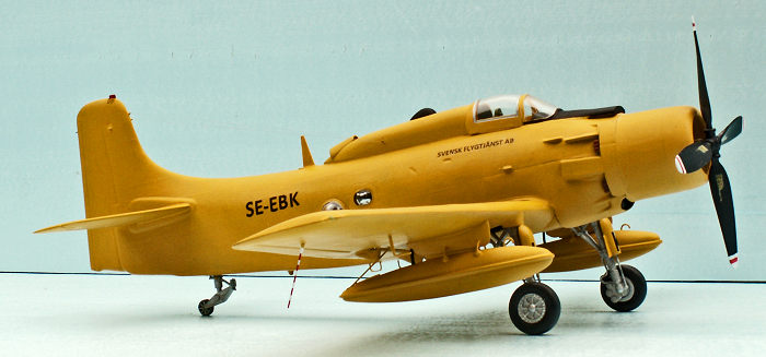
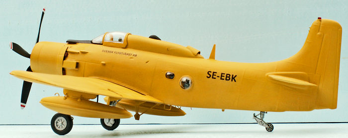
Fortunately these aircraft were preserved and three of them went to the USA: The SE-EBK went to Pacific Fighters, Chino as N4277N, the SE-EBL went to National Airplane Museum as N5469Y, and the SE-EBM went to Cham S. Grill, Medford Or. As N4277L. The SE-EBF crashed in 1976 at Luleå.
Three other Skyraiders were stored earlier and eventually ended in Aviation Museums: The SE-EBB is in the Aviation Museum in Stockholm, Arlanda Airport. The SE-EBC is in Svedino’s Car and Aviation Museum at Ugglarp, and the SE-EBI is in Airmuseum Sweden. The four aircraft not accounted for were all scrapped at Bulltofta in Malmö from 1974.
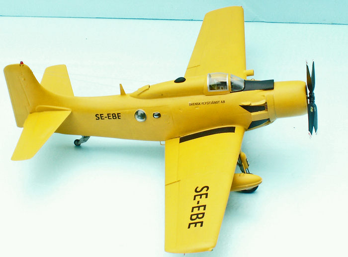
I visited Bulltofta Airport in August 1963 invited by Bo Göran Lundkvist, an employee of the airline Transair Sweden. My camera had a good day, taking pictures of Skyraiders SE-EBE and EBK, Meteor TT 20 SE-CDF and Firefly TT SE-CAW. The subjects of my two Skyraiders are of course the EBE and the EBK. The EBE was in a hangar and the EBK was parked outside, an almost brand new aircraft without the black areas painted behind the exhaust pipes.
| THE KIT |
The Kits: 4046: The AD-4W would be the right kit for the Swedish target tug version, because the originals were converted from this version of the Skyraider. The kit comes in a suitable box with a picture of the “fleet eye”on the top of the box. The sprues are in a very dark navy blue styrene, and the clear parts are of a good quality. The instructions is a large fold-out paper with six pages. One and two gives the story of the Skyraider in Italian, English, German and Spanish. Pages three and four show how to assemble the kit in seven exploded sketches. Pages five and six show how to paint and decal the two options of the kit: a US Marines AD-4W from the Korean war, and a Royal Navy AEW 1 from sqn. 849 during the Suez crisis in 1956. The decal sheet is of a very high quality printed by Cartograf.
The kit has some flaws: The cowling front (4A) has a wrong shape, and the opening is too small. The tail planes are too long by 4-5 mm. The intake in the rear end of the “saddle” behind the cockpit has a wrong shape. The intake above the cowling is too narrow. The assembled cockpit section is rather difficult to glue properly in place. It tends to fall down. The assembly of the main undercarriage legs is not possible to make from the kit without some modification, and the windscreen has no outer framing in the front.
 For the
Swedish target tug version, the radar dome (37D + 38D and the tail plane fins
(48D), and the arrester hook (12A) should not be used. The holders for the wing
tanks (44D) must be scratch-built, since they do not reach the tanks –being too
short.
For the
Swedish target tug version, the radar dome (37D + 38D and the tail plane fins
(48D), and the arrester hook (12A) should not be used. The holders for the wing
tanks (44D) must be scratch-built, since they do not reach the tanks –being too
short.
Kit 4040: the single seat AD-6 version. This kit is more difficult to use as a basic kit for the target tug version. It comes in a similar box as the AD-4W, however, with an AD-6 on the top of the lid. The sprues are in a dark green color, the clear parts are the same as for the AD-4W kit. There are some more sprues, because of the option of a full load of weapons to be carried under the wings. However, all of these can go to the spares, because the target tug is unarmed.
This kit has the same flaws as the AD-4W. However the main undercarriage is different, because the wheels are protected by doors. The instructions is a large fold-out paper with 8 A4 pages. Page one and two tell the story of the Skyraider, exactly as with kit 4046. The next page is page five, because of the way of folding the paper, which contains some good advice for the assembly. The next two pages, three and four, is a plan for the assembly of the kit with seven exploded sketches. Finally, pages six, seven and eight show how to paint and decal the three options of the kit: two planes of the USAF and one of the Vietnamese AF. The decals are of the same high standard as with the 4046 kit, also printed by Cartograf.
| CONSTRUCTION |
I will start with the easy one, the AD-4W. A thorough study of my photos of the real thing revealed some flaws. Most important: the cowling front of the kit has a wrong shape making the gauge of the air cooling inlet too small by some 2 mm. It would be too troublesome to modify the kit part (4A), and therefore I turned a new cowling front on the lathe with a piece of Ureol as workpiece. I glued the workpiece to the end of a small plastic tube with a suitable gauge for the purpose. The outer shaping was simple, the inner shaping was more complicated. However, the result was useable. My photos showed the front cooling flaps, and they were not with the kit. When a Skyraider engine is shut down, these flaps are closed, and it is not possible to see the cylinders. I made a disc from plastic card, gauge 26 mm, and with a 9 mm gauge hole in the center. This disc was cut radially in twelve equal pieces, and these fit rather well inside the cowling in front of the cylinders. They should be painted yellow before application.
Another important modification is to sand away the armor plating on the sides beneath the canopy and on the underside of the fuselage and wings. This is a major job, which must be done by hand using some files of different coarseness. A file covered with diamond grains is good for a start. Only about one mm of the thickness should be removed. It was easy to see, when the job was finished. So much trouble for one mm, which is hardly noticeable on a finished model!
 The hump
between the upper and lower exhaust pipes must be filed away and replaced by a
more angular and longer one. Since it is open behind, it must have something to
do with the airflow cooling of the cylinders.
The hump
between the upper and lower exhaust pipes must be filed away and replaced by a
more angular and longer one. Since it is open behind, it must have something to
do with the airflow cooling of the cylinders.
A real problem was the main undercarriage legs, which it was not possible to apply according to the instructions. Part no 30B did not conform with the holes in the wing. I simply cut off the lower part of the leg with the pins for the holes. Then I placed some insulation from an electric wire in the two ends of the legs and glued these to a place approximately at the holes with white glue. It did not look right in the wheel well, but it was the only way to make a reasonable assembly of the undercarriage legs to make them look right from the side and from the front simultaneously. Never mind the look in the wheel well!
The intake on the underside of the cowling base did not look like the real thing and had to be sanded for a better shape. The intake in front of the windscreen was too narrow and had to be widened by some five mm. However, this operation was done with an otherwise finished model, because I did not notice this flaw, until my son told me! It would have been a lot easier to correct this flaw at an early stage of the construction. This operation became a challenge in the end!
The two large wing tanks of the kit were the right size and shape for the target tug, and this was a good thing. However, it was not possible to glue them in place on the pylons 45D, because the fittings 44D did not fit to the tanks. They were too short. I had to scratch-build new ones, using 0.5 mm wire and gauge 1.8 mm roundels punched from 0.25 mm plastic card. The roundels got a 0.5 mm hole in the center. This was possible to do, because the four roundels stuck in the circular punch, and this was easy to clamp in the three- jaw chuck of the lathe. It was a piece of cake to drill the 0.5 mm holes exactly in the center of the roundels.
Then I drilled four 0.5 mm holes in the pylons where the fittings should be. A 15 mm long 0.5 mm wire was pulled through each hole, and the ends were bend downwards with round pliers to reach the tanks. The tanks were placed on the wire ends and these were cut in length for the right position of the tanks. Finally the 1.8 mm discs were glued to the ends of the wires and the tanks were put back to secure the right slope of the discs. White glue was excellent for this job. The following day the tanks were removed, and showed some fittings as they should be with the kit.
 The wind
screen had no outer framing in the front, and the two vertical frames had to be
sanded away. I used a triangular needle file for the removal of the frames, wet
sanding with grain 1200 wet sanding paper and toothpaste to regain full
transparency. The rear edge of the hood must be filed thinner at the inner side
if it shall conform properly to the saddle. No toothpaste necessary here,
because the edge will be covered by paint in the end. The hood conformed so well
with the saddle that no glue was necessary to keep it in place.
The wind
screen had no outer framing in the front, and the two vertical frames had to be
sanded away. I used a triangular needle file for the removal of the frames, wet
sanding with grain 1200 wet sanding paper and toothpaste to regain full
transparency. The rear edge of the hood must be filed thinner at the inner side
if it shall conform properly to the saddle. No toothpaste necessary here,
because the edge will be covered by paint in the end. The hood conformed so well
with the saddle that no glue was necessary to keep it in place.
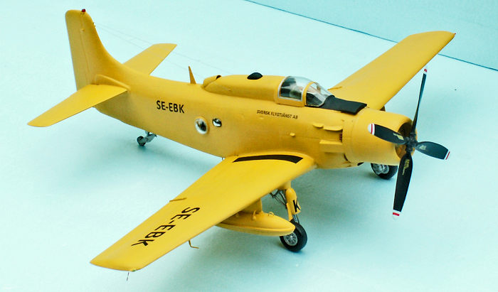
The opening for the arrester hook must be filled with putty, and so the four small openings in the wings for spent cartridges. The two side walls, 52D + 53D, with the entrance to the target operator’s room must be fitted with the windows, 4E, and with a large dome enabling the observer to watch, what is happening outside. This dome was of course not with the kit. In my spares, I found some spare domes from an Airfix B-29 1/72, which came with two sets of transparent sprues. These domes were close to the right size and shape. The position of the dome was a good question! I made a mistake by placing the domes as shown on the drawing by Björn Karlström. I did not detect this mistake, until the model was almost finished including the painting. Therefore, it was not possible to make a correction on the SE-EBE. However, the second model, the EBK, got the right position of the domes according to my photos! Never trust a drawing –only photos of the real thing are reliable as documentation for a model.
| CONSTRUCTION |
The AD-6 kit is a greater challenge than the AD-4W for creating a Swedish target tug Skyraider! Since the two kits are basically the same, I shall only deal with the specific problems to be solved for the target tug version. The main issues are to produce the saddle and the two large wing tanks. All other problems are dealt with during the construction from the AD-4W kit.
T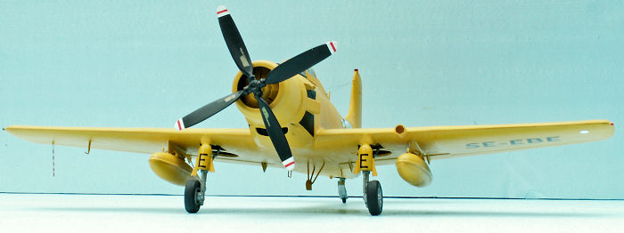 he
saddle was made of a piece of Ureol, artificial wood, that is, you can use your
tools for woodwork making the right shape. It takes some time to get the right
shape as seen from the side and from above. The bottom must be concave,
corresponding to the convex curving of the fuselage. White glue is OK to fix the
saddle to the fuselage, and it is most convenient for dealing with small gaps. A
finger is a useful tool for smoothing the white glue in gaps.
he
saddle was made of a piece of Ureol, artificial wood, that is, you can use your
tools for woodwork making the right shape. It takes some time to get the right
shape as seen from the side and from above. The bottom must be concave,
corresponding to the convex curving of the fuselage. White glue is OK to fix the
saddle to the fuselage, and it is most convenient for dealing with small gaps. A
finger is a useful tool for smoothing the white glue in gaps.
The intake in the rear of the saddle was made of a small piece of acryl tube. The front opening should be about 9 mm wide, declining to about 6 mm in the rear. To get this effect the tube was cut through in an angle, and the edges were filed to match the curving of the saddle. The front end was heated, and made somewhat larger. The result looked very much like the real thing.
The large wing tanks were a typical job for the lathe. A piece of Ureol was turned to a rod with the max. gauge of the tanks. With a minidril and a cutter it only took a couple of minutes to shape the contour of a tank roughly. Sandpaper made the final shaping and a proper finish. I chose to turn the front end first, and after cutting the workpiece off the rod, it was clamped in the three-jaw chuck with the front end inside. Now the rear end was shaped, and the tank was finished so far.
The tanks would not be right without the rim in the middle. Of course, it would be possible to glue a 0.25 x 0.5 mm plastic strip around the tank. However, it would be much easier and safer to cut the tank trough in the middle, and glue a piece of 0.25 mm plastic card between the halves. The problem here is, how would it be possible to cut a tank through exactly in the middle? A band saw could do the job, if you can guide the tank absolutely steady against the saw band. The problem is only a question of fixing the tank in a way to secure its dividing in two equal halves.
 My
experience from building wind tunnel models on a professional basis told me how
to do it. Foam is used for wind tunnel models for two reasons: 1) It is easy to
process, an 2) the finish is not smooth, which means enough resistance for the
measuring in the wind tunnel. The problem is how to clamp a circular workpiece
in a way that allows the use of a band saw with a very fine cutting blade to do
the dividing job. If I could place the tank firmly in a block of foam, this
would make up for a secure clamping. To do this I had to drill a hole with a
slightly smaller gauge than that of the tank. However, drilling a hole in foam
can only happen with a special drill. A normal drill will only destroy the foam!
The right drill for foam is a tube with a sharp edge, like a punch. This tool
goes easily through the foam making a nice cork with the inner gauge of the
tube.
My
experience from building wind tunnel models on a professional basis told me how
to do it. Foam is used for wind tunnel models for two reasons: 1) It is easy to
process, an 2) the finish is not smooth, which means enough resistance for the
measuring in the wind tunnel. The problem is how to clamp a circular workpiece
in a way that allows the use of a band saw with a very fine cutting blade to do
the dividing job. If I could place the tank firmly in a block of foam, this
would make up for a secure clamping. To do this I had to drill a hole with a
slightly smaller gauge than that of the tank. However, drilling a hole in foam
can only happen with a special drill. A normal drill will only destroy the foam!
The right drill for foam is a tube with a sharp edge, like a punch. This tool
goes easily through the foam making a nice cork with the inner gauge of the
tube.
The hole must be absolutely parallel with the side of the block of foam. Now I could press a tank into the hole in the foam block, and the tank would be clamped absolutely firm. With this auxiliary tool it was a piece of cake to cut the tank in two identical halves with the band saw.
A half tank was used as a template for drawing the rim pieces on 0.25mm plastic card. The rims were cut, and now the tank halves could be glued together with the rim piece in between. Super glue was best for this operation. At last some trimming of the rims was done, securing the right width all around.
The pylons for the wing tanks were made from parts 49C. They should be modified to the same shape as part no 45D from the AD-4W kit.
The last item needing special care were the “trousers”, the rounded doors protecting the undercarriage legs, when the gear is up. They are of a wrong shape with the kit, parts 28B + 29B. They are too broad downwards. Parts no 61C + 62C provided the new trousers. The rear end cut in the length of part 28B was a well suited workpiece. They should be sanded a little smaller in the open end, and some small pieces of 0.25 x 1 mm plastic strips should be glued on in both sides. The length of these strips are different, smallest on the inner sides of the trousers.
| COLORS & MARKINGS |
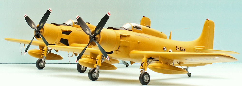
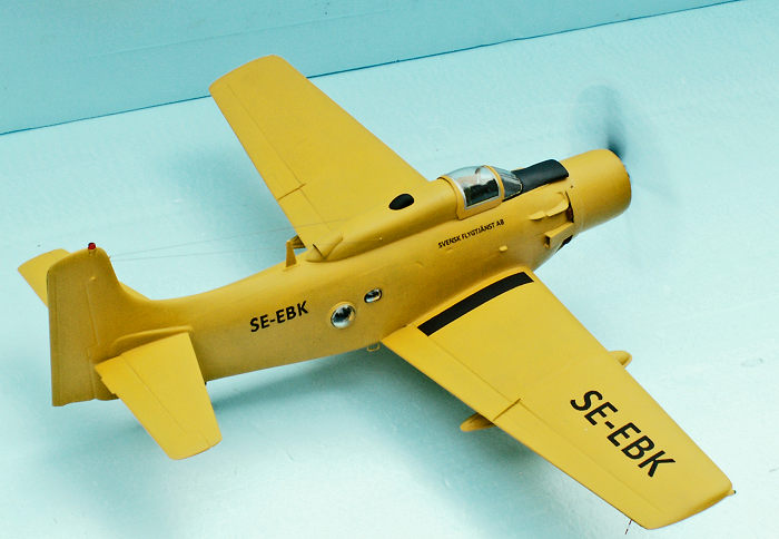
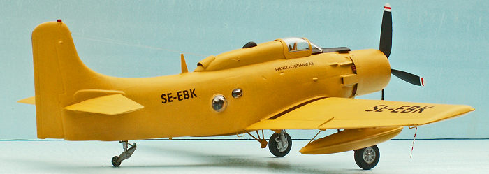
 The color
scheme of the Swedish target tugs is very simple: trainer yellow (HB 24) over
all – including wheel wells. Undercarriage legs are aluminium, tires are rubber
black. Propellers are engine black with white tips and a red stripe. The intake
in front of the windscreen is engine black, and so are the triangular figures
behind the exhaust pipes, likewise the walkways on the wings and the small hump
on the saddle. Registration letters and text beneath the cockpit “SVENSK
FLYGTJÄNST AB” are black. The decals were printed on a piece of clear decal
paper. My printer did, however, a bad job, and there was a lot of touch up to
get a reasonable result.
The color
scheme of the Swedish target tugs is very simple: trainer yellow (HB 24) over
all – including wheel wells. Undercarriage legs are aluminium, tires are rubber
black. Propellers are engine black with white tips and a red stripe. The intake
in front of the windscreen is engine black, and so are the triangular figures
behind the exhaust pipes, likewise the walkways on the wings and the small hump
on the saddle. Registration letters and text beneath the cockpit “SVENSK
FLYGTJÄNST AB” are black. The decals were printed on a piece of clear decal
paper. My printer did, however, a bad job, and there was a lot of touch up to
get a reasonable result.
| FINAL CONSTRUCTION |
The following parts were added after the painting and decaling: Pitot tube under the SB wing, VHF antenna under the SB wing tip. This was painted white with broad red rings. The latter were done with a Posca 0.7 mm marking pen. A landing light was punched from some surplus self-adhesive metal foil, gauge 4.8 mm. The structure for guiding the tug wire was made of a small piece of sprue and three pieces of 0.8 mm brass wire. The look of this detail is wrong on the drawing by Björn Karlström, but photos from a walk around from a Swedish Museum showed how the real thing looked like. The small black hump on the top of the saddle was made of a piece of Ureol.
 The beacon
on the top of the fin was made of a small piece of clear sprue, gauge 2.5 mm and
about 1.8 mm high. The basis for the beacon was a small piece of sprue, gauge 3
mm. In order to place this basis correct, I found it necessary to produce a jig
to clamp the finished model securely, because it was a milling job to make a
precise opening for the basis in the fin. It was a challenge to produce this
jig! So much trouble just for the sake of a small beacon. The clear part was
colored red with a transparent red marking pen, and this looks great.
The beacon
on the top of the fin was made of a small piece of clear sprue, gauge 2.5 mm and
about 1.8 mm high. The basis for the beacon was a small piece of sprue, gauge 3
mm. In order to place this basis correct, I found it necessary to produce a jig
to clamp the finished model securely, because it was a milling job to make a
precise opening for the basis in the fin. It was a challenge to produce this
jig! So much trouble just for the sake of a small beacon. The clear part was
colored red with a transparent red marking pen, and this looks great.
Under the operator’s cabin there are some foot rails, which were made of gauge 0.5 mm wire. The sword antenna just behind the saddle was made of 0.25 mm plastic card, glued to a small piece of the same material 1.5 x 6 mm as basis. The twin wire antennas were made of 0.1 mm gauge nylon and fastened by 5 mm long pieces of 0.5 mm brass tubes, inner gauge 0.3 mm. This system produces a very realistic wire antenna, which is not too thick. However, it requires a careful handling of the model, because it is almost invisible from a normal looking distance.
Finally, the EBE got new trousers made in the same way as those of the EBK. Now the only differences between the two models were the position of the observer’s dome, and the length and shape of the tail planes, which was modified for the EBK, 4 mm shorter and a changed angle of the front edges.
| CONCLUSIONS |
Conclusion both kits: The ESCI kits are rather old and with some flaws. Nevertheless, it is possible to make a reasonable model of a Swedish target tug either from the AD-4W kit or from the AD-6 kit, the AD-4W being the most obvious choice. Both kits are recommendable as basis kits for the unique Swedish Skyraider TT. A more sophisticated kit is not necessarily a better choice for this conversion. Anyway, it will be a lot more costly! Moose Republic Decals used to have a 1/48 sheet covering the Swedish Skyraider TTs with four marking options. However, this sheet has been out of print for a long time. I might have needed one!
| REFERENCES |
Björn Karlström: Flygplansritningar 7 – Flygplan och helikoptrar I svensk offentlig tjänst (aircraft and helicopters in Swedish public service). Allt om Hobby, ISBN 91-85496-68-5
Photos and a drawing of the target tug Skyraider.
Peter C. Smith: Skyraider – The Crowood Press Ltd. Ramsbury, Marlborough. ISBN 1 86126 249 3
Chapter Thirteen: Target Tug – The Swedish Experience.
My own photos of the SE-EBE and SE-EBK taken at Bulltofta, August 1963.
11 September 2018
Copyright ModelingMadness.com If you would like your product reviewed fairly and fairly quickly, please
contact
the editor
or see other details in the
Note to
Contributors.
Back to the Main Page
Back to the Review
Index Page
Back to the Previews Index Page