| KIT #: | 619 |
| PRICE: | $48.00 |
| DECALS: | Two options |
| REVIEWER: | John Summerford |
| NOTES: | Yahu instrument panel and Scale Aircraft Conversions landing gear and engine mount used. |
| HISTORY |
Courtesy of Wikipedia
The Cessna L-19/O-1 Bird Dog is a liaison and observation aircraft. It was the first all-metal fixed-wing aircraft ordered for and by the United States Army following the Army Air Forces' separation from it in 1947. The Bird Dog had a lengthy career in the U.S. military, as well as in other countries.
The U.S. Army was searching for an aircraft that could adjust artillery fire, as well as perform liaison duties, and preferably be constructed of all metal, as the fabric-covered liaison aircraft used during World War II (primarily Stinson and Piper products) had short service lives. The U.S. Army issued the specification for a two-seat liaison and observation monoplane.
 The Cessna Aircraft Company
submitted the Cessna Model 305A, a derivation of the Cessna 170. Deliveries
began in December 1950, and the aircraft were soon in use fighting their first
war in Korea from 1950 through 1953.
The Cessna Aircraft Company
submitted the Cessna Model 305A, a derivation of the Cessna 170. Deliveries
began in December 1950, and the aircraft were soon in use fighting their first
war in Korea from 1950 through 1953.
During the early 1960s, the Bird Dog was flown by the Republic of Vietnam Air Force (RVNAF), U.S. Army, and U.S. Marines in South Vietnam and later by clandestine forward air controllers (e.g., Ravens) in Laos and Cambodia. Because of its short takeoff and landing (STOL) and low altitude/low airspeed capabilities, the O-1 also later found its way into U.S. Air Force service as a Forward Air Controller (FAC) aircraft for vectoring faster fighter and attack aircraft and supporting combat search-and-rescue operations recovering downed aircrews.
On April 29, 1975, the day before the fall of Saigon during the Vietnam War, Republic of Vietnam Air Force Major Buang-Ly loaded his wife and five children into a two-seat Cessna O-1 Bird Dog and took off from Con Son Island. After evading enemy ground fire, Major Buang-Ly headed out to sea and spotted the aircraft carrier Midway. With only an hour of fuel remaining, he dropped a note asking that the deck be cleared so he could land. Knowing there was no room for this to happen, Midway's commanding officer, Captain (later Rear Admiral) Lawrence Chambers ordered $10 million worth of South Vietnamese Bell UH-1 Iroquois ("Huey") helicopters to be pushed overboard into the South China Sea. The Bird Dog that Major Buang-Ly landed aboard Midway is now on display at the National Naval Aviation Museum at Naval Air Station Pensacola, Florida.
| THE KIT |
Inside one bag are eight light-gray sprues and one sprue of clear parts. I immediately put the clear sprue into a separate bag. Another small bag has three lengths of wire for use as antennae. Detail on the parts is crisp with some minor flash and mold seams. Total parts count is 159. The main landing gear legs on the aircraft are spindly and Roden has faithfully reproduced them. I’m sure they will take the weight of the model, but they might be easy to knock off during assembly.
 On the first page of the
instructions are three different languages (Cyrillic, English, and German) about
the history and specs Page two has assemble tips and color call-outs for Vallejo
pints and a parts map that extends to the third page. Assembly starts with the
engine and jumps around a bit to landing gear and seat assembly. (Maybe while
glue is setting up on the engine?) Page six has the 25th and final step and the
last two pages are devoted to paint and decaling instructions.
On the first page of the
instructions are three different languages (Cyrillic, English, and German) about
the history and specs Page two has assemble tips and color call-outs for Vallejo
pints and a parts map that extends to the third page. Assembly starts with the
engine and jumps around a bit to landing gear and seat assembly. (Maybe while
glue is setting up on the engine?) Page six has the 25th and final step and the
last two pages are devoted to paint and decaling instructions.
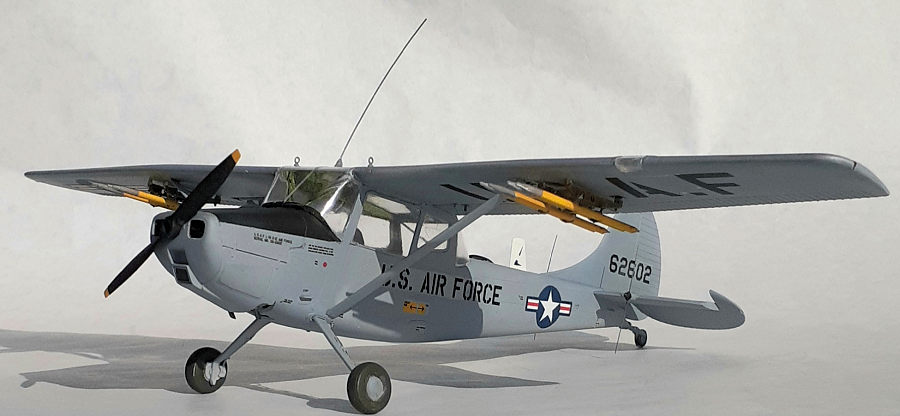
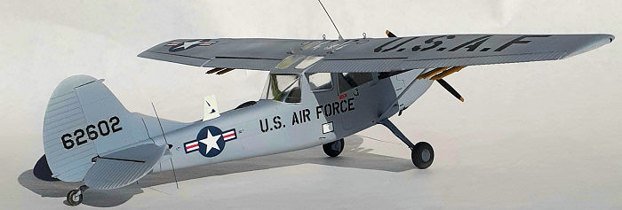
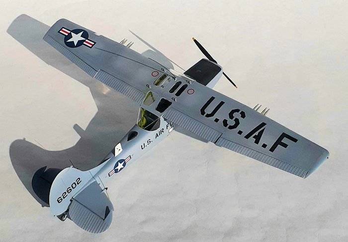
Two modeling options are provided and there are slight differences between them, so attention must be paid to which parts to use. The first option is a colorful Army aircraft in olive drab and orange stationed with the training school at Fort Rucker Alabama. The other option calls for a natural metal aircraft used by the Air Force as a FAC stationed at Da Nang Air Base in 1966. A quick search on the internet revealed that these aircraft were painted light gray.
| CONSTRUCTION |
Frank Reynolds built this kit when it first came out in late 2017. His review can be seen here.
According to the instructions, the build starts with the engine. All of those parts, save for the mufflers, are on sprue “E”. It appears that I didn’t get the engine mounts glued in their proper place on the engine block, and there are not any reference points to use for alignment. Everything else went into place easily. I’m glad that I had the metal mounts from Scale Aircraft Conversions, because I had to bend them to fit to the firewall.
There is not much to install into the cockpit. I chose to build the forward seat from the floor up. I found that it was easier to get all of the frame work to line up. I added seat belts plus control cables between the two throttle quadrants. Part 2D (a leather pouch for papers) is shown as attaching to the door and also to the right of the rear seat. It makes more sense to glue it to the door.
 The instructions call for
gluing on the landing gear to each fuselage half and then install the glazing to
each side. I left adding the gear for later. Some of the glazing needed
trimming. The halves were mated and then the rear seat dropped into place.
The instructions call for
gluing on the landing gear to each fuselage half and then install the glazing to
each side. I left adding the gear for later. Some of the glazing needed
trimming. The halves were mated and then the rear seat dropped into place.
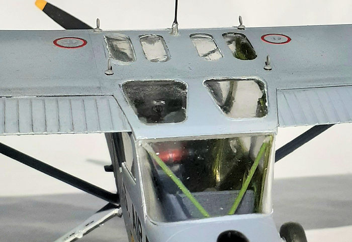
Test fitting the front and rear windshield revealed major fit issues. Taking a page from Mr. Reynolds review I added a spreader from a length of brass tube between the roof frames for the rear windshield.
When it came to the front windshield, the fit was horrible at the upper “corners” where the wing leading edge fits. Material was filed of the outer edges and the lower portion of the opening that matches the wing. Material was also removed from the leading-edge roof frame. I couldn’t get the windshield to sit properly between the roof frames because they were too close together, so I glued in place the single piece upper wing. The trailing edge of the wing needed sanding down to get a good fit at the rear.
The front and rear “V” frame pieces that are under the windshields were glued in place and then the clear parts followed. I sat back and let out a sigh when I finished this step.
Turns out, I shouldn’t have relaxed so soon. I thought I was being clever when I attached the upper wing piece. Only problem was; I forgot to glue the windows in place. Holding the model up-side-down, I maneuvered to roof windows in place one at a time through the back-window openings, (more by luck than skill) tipped the model up slightly and used extra thing liquid glue to secure them in place. None of clear pieces fit well, so I flooded them with Future floor finish. I’m surprised how well that worked. The lips around the sides and aft ends of the last two windows were filed off. Using some tape to keep the windows from falling in, they were slipped into place and glued applied to the front lips. When that set, the tape was removed and additional glue added to the rear edges. These too were finished off with Future.
 In order to protect the
clear pieces, and afternoon was spent masking them. For the “corners”, small
circles of tape either cut from metal templates, or pressed onto a scrap of card
stock and punched out from a die. The sides were filled in with straight lengths
of tape.
In order to protect the
clear pieces, and afternoon was spent masking them. For the “corners”, small
circles of tape either cut from metal templates, or pressed onto a scrap of card
stock and punched out from a die. The sides were filled in with straight lengths
of tape.
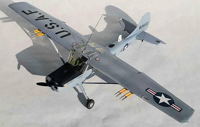
Completing the wing was unusual. The upper wing on this example had a slight drop across the span, so a piece of basswood strip stock was held to the upper wing while the lower piece was being glued with the help of a clamp. A gap resulted between the lower wing pieces and the fuselage. This was exploited in setting the slight dihedral in the wing. Placing the model upside-down on a small pedestal, the struts were glued to the fuselage. When those joints were set, the wings were flexed down until the struts aligned with the wing attachment points and glued. While they were curing, cyano glue was applied to the gaps and that set the dihedral. I’m pleased at how well that worked.
Roden did a great job engineering the tail surfaces, it’s impossible to get the stabilizers miss aligned. Just a small amount a filler was needed at the forward seam. The elevators are a single piece and were installed in a drooped position. Blobs of liquids mask were daubed on the mounts for the antennae on the stabilizers.
Scale Aircraft Conversion’s landing gear was glued in place. The main legs needed some bending to get the right angles. The tail wheel strut bends too easily, so a coat of cyano applied for stiffness. The model was ready for paint.
| COLORS & MARKINGS |
I have a hard time resisting colorful paint schemes, but this time I went with the boring gray of the Air Force option and see what I could do with weathering effects. A couple coats of rattle can automotive primer were sprayed on. Opaque light gray was sprayed on the undersides with feathering along the fuselage sides where more exposure to sunlight would occur. The upper surfaces received a lighter application with the areas between the panels getting highlights of a paler gray. When all was dry, artist charcoal was rubbed into the panel lines and blended around the seams. The anti-glare panel was masked around and painted on.
 A couple of gloss clear
coats prepped the model for decals.
A couple of gloss clear
coats prepped the model for decals.
Roden decals have a poor reputation and I’m sorry to confirm it. There is some bleed of the red and blue ink on the stars and bars and I would have replaced them if I had any in this scale on hand. Starting with the underside of the wing, the U.S.A.F decal had the “F” break into three pieces and the letter height is too large with interference between the strut and flap hinge. Micro Sol got it to settle down. It would be easier to handle the decal by splitting it between the “S.” and “A”, which I did on the top side. About half of the decals broke into two pieces when being applied, and I was able to tease into place. I used duplicate stencil decals several times and didn’t bother with the smallest stencils. After a couple of coats of clear flat, the decals looked OK and carful dusting with a soft brush of light sand pigment gave them a subtle weathered look.
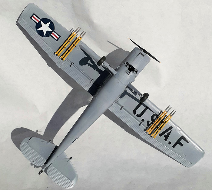
The rockets were added as well as the wheels. Perhaps the most nerve-wracking step was attaching the antennae to the stabilizers. Holding the model vertically on the bench top, the wires were balanced on the mounting points and puddle of liquid cement dropped on with a syringe and then the caps pressed into place. After that, the dorsal antennae were a piece of cake. As per my usual practice, the prop was added last.
| CONCLUSIONS |
Saying that getting the clear pieces to fit properly was a challenge is to understate the problem. Along with the decals, they are the biggest issues with the kit and leave much room for improvement. I’m glad I waited to glue on the landing gear. I would have knocked them off. Because the metal tail strut bends very easily, it might be better to use the kit parts. I’m glad that I have another unusual model on my shelf, but it’s far from the best.
13 July 2021
Copyright ModelingMadness.com. All rights reserved. No reproduction in part or in whole without express permission.
If you would like your product reviewed fairly and fairly quickly, please contact the editor or see other details in the Note to Contributors.