Roden 1/32 Cessna O-1 Bird Dog
| KIT #: | 619 |
| PRICE: | £32-00 |
| DECALS: | Two options |
| REVIEWER: | Frank Reynolds |
| NOTES: | HGW generic USAAF/US Navy Seat Belts no 132085 (£7-99) ; Scale Aircraft Conversions metal gear legs 32113 (£16-50) ; Airscale generic US Navy Instrument dial decals no AS32 (£4-25). Montex Maxi Mask set MM32174 (£6-50). |
| HISTORY |
When the US Army issued a requirement for an all-metal Observation and Liaison light aircraft to replace the steel tube and fabric types that had served during World War 2, it was met by Cessna with new design that incorporated major elements of its 170 series civil light plane. The rework featured two seats in a fore and aft configuration, with the side cabin windows angled outwards to provide a measure of downward vision. The rear fuselage was cut down so that a large window could provide rearwards vision - a feature that would later become standard on Cessna’s single engine civilian light planes.
 The type first flew in
December 1949, entering service the following year and it was to last into the
1970s in military service.
The type first flew in
December 1949, entering service the following year and it was to last into the
1970s in military service.
The L-19 is a good example of industrial design where form follows function, essentially so simple in its concept, so right for its intended use, so easy to operate and maintain that it achieved wide acceptance with a range of military users in some 23 countries. Over 3400 were built. The L-19E was the second most widely produced variant with 469 aircraft built in 1956/7. It featured a reinforced airframe and a wing with four hard points. The build up in Vietnam led to the production line being re-opened and a further 97 aircraft were built between 1961 and 1963. In September of 1962 the US Department of Defense standardised aircraft designations resulting on the L-19E becoming the O-1E.
The L-19 was powered by a Continental 0470-11 6-cylinder horizontally opposed air cooled engine of 210hp , itself an industrial classic.
The Bird Dog has acquired an iconic status for a number of reasons. It was prominent in its role as a Forward Air Controller in Vietnam - the first war to be fought in the full glare of television reporting. It also forms a strong branch of the family tree of the most-produced aircraft type in history - the Cessna 170/172series, over 50,000 built and still in production
 THE PROJECT
Someone at Roden is fond of less obvious aircraft subjects from the Vietnam era. In their catalogue in various scales are C-119, C-123, OV-1, AU-23 and T-28. Now comes the L-19 in big scale.
I bought this kit at IPMS UK’s Scale Model World 2017 in November at Telford. At this expo, the same kit was being offered at prices ranging from £32-00 (which is what I paid ) to £54-00. It surely pays to shop around at a big show.
An injection moulded L-19 first appeared from Airfix in a 1:72 offering in 1976 and a 1:48 version from Model USA in 1988. So, while never a prolific subject in kit manufacturers’ lists, this Cessna warbird occupies enough pages in aeronautical history to justify a new offering.
Although a light aircraft it is by no means small, having a wingspan of 345mm.
| THE KIT |
Artwork is purely subjective but I happen to like Roden’s comic book style of box top artwork showing an O-1 cruising over a jungle canopy and wooded hills while a pair of Skyraiders swoop in the back ground. The standard tray-type box is about 30% too big for the contents and although the parts are contained in one plastic bag, the transparencies were free to rattle around inside, fortunately without damage. There are six parts frame in a slightly soft grey plastic and one in clear. A small bag contains three wire aerials.
Two finish options are
offered. First is a US Army aircraft in Olive Drab with Orange panels operated
by the US Army training school at Fort Rucker, Alabama, 1965. Second is a US Air
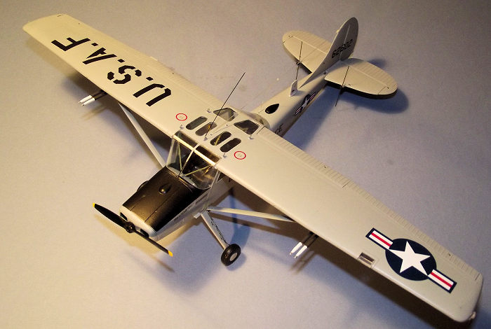
Force machine at Da Nang ,
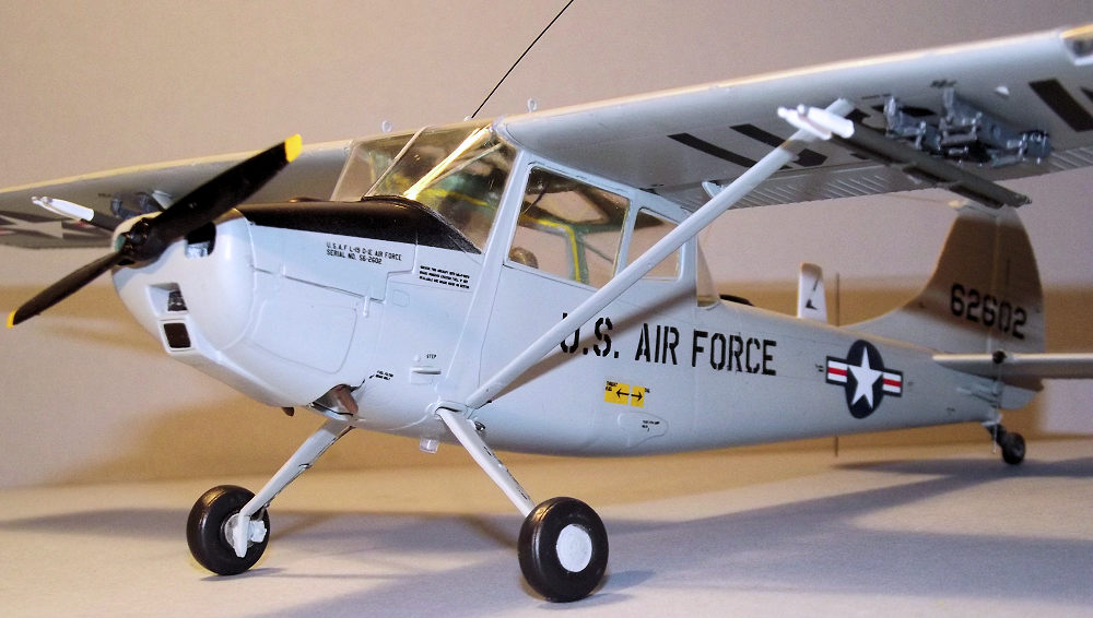
 South Vietnam, 1966, finished in overall Light Grey
with a Black anti-glare panel. They differ slightly in arrangement of radio
aerials and the instructions make this clear.
South Vietnam, 1966, finished in overall Light Grey
with a Black anti-glare panel. They differ slightly in arrangement of radio
aerials and the instructions make this clear.
The decals are sharply printed and the colours appear to be of good density and include a good range of airframe stencils. There is no instrument panel decal.
The instructions run to seven pages, A4 size in Black and White. There is a parts chart and four-view painting guides linked to Vallejo paints only. There is potential to build the L-19 with the pilot’s door open, the main side windows swung up to the horizontal and the engine covers open. Under wing stores consist of four target marking rockets.
The plastic parts closely
resemble those of a short run product. Surface detailing consists of light and
restrained recessed panel lines, the control surfaces featuring a convincing
representation of the corrugated strengthening ribs .Some of the subassemblies
such as the engine and seats are a rather fussy collection of small parts and
the crowded pictograms are not too clear on parts locations. Where locating pins
exist on components, and not all have them, the corresponding locating holes
need to be checked to ensure that they are deep enough and some had to be
drilled out to fit. Some flash was present on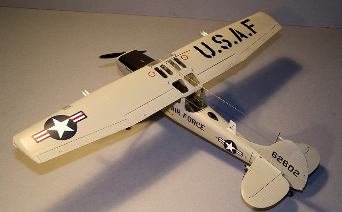 the parts and prominent mould
lines were present on smaller parts. Awkwardly, many of the plastic feeds from
the runners to the moulded parts occurred at the joining faces of the parts and
needed to be carefully trimmed away. This was especially difficult on the
stepped edges of the side window mouldings and their frames. There was
noticeable sinkage on the full span moulding of the upper wing parts running as
a shallow trench just forward of the hinge line for the flaps and ailerons and
two small areas of sinkage on the fuselage sides immediately above the main
landing gear mounts. Roden’s instructions are not the clearest and the assembly
sequence as set out is best regarded as a guide to where the parts should end
up. The 25 part engine assembly is covered by stages 1 through 5 but for no
logical reason the builder is invited to construct the tail wheel assembly at
stage 4. Similarly eccentric, Roden also invites the builder to install the
horizontal tail sections, complete with aerials and to glue in the main landing
gear before the fuselage halves are joined, so plenty of advance planning is
recommended.
the parts and prominent mould
lines were present on smaller parts. Awkwardly, many of the plastic feeds from
the runners to the moulded parts occurred at the joining faces of the parts and
needed to be carefully trimmed away. This was especially difficult on the
stepped edges of the side window mouldings and their frames. There was
noticeable sinkage on the full span moulding of the upper wing parts running as
a shallow trench just forward of the hinge line for the flaps and ailerons and
two small areas of sinkage on the fuselage sides immediately above the main
landing gear mounts. Roden’s instructions are not the clearest and the assembly
sequence as set out is best regarded as a guide to where the parts should end
up. The 25 part engine assembly is covered by stages 1 through 5 but for no
logical reason the builder is invited to construct the tail wheel assembly at
stage 4. Similarly eccentric, Roden also invites the builder to install the
horizontal tail sections, complete with aerials and to glue in the main landing
gear before the fuselage halves are joined, so plenty of advance planning is
recommended.
| CONSTRUCTION |
This began with the
interior and it was something of a disappointment to find that the interior of
the cabin was rather sparsely detailed, more to the standard of a 72nd scale
kit. I became more dismayed after a trawl of the web produced a series of photos
showing the cockpit of a Bird Dog to be a busy place with plenty of cables and
wires in view. The start was promising with the pilot’s seat being a six-part
assembly that adequately conveys the tubular framing, the rear seat being a
simple flat section with an upright flat back. The seat upholstery seemed a
little skinny so I built up both seat cushions and backs with sections of
15thou. plastic card, then covered them with pieces of soft tissue paper soaked
in liquid cement to try to create the impression of fabric seat covers. Trimmed
pieces of the same soft tissue were fixed to the inside cabin walls to give some
suggestion of the padding fixed in these areas. The instrument panel was painte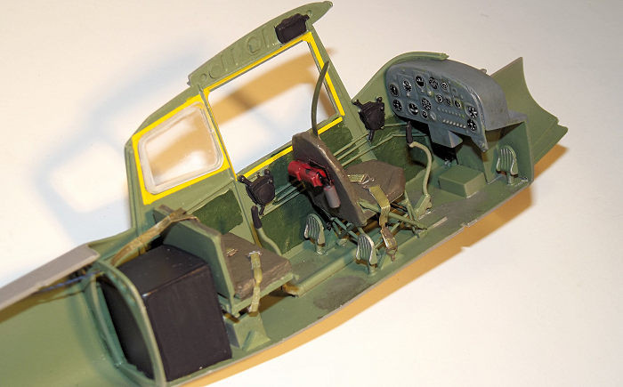 d
pale grey then I fiddled around for a couple of hours fixing 15 separate dials
from the Airscale decal sheet, each of which needed to be varnished into place
before the next could be applied.
d
pale grey then I fiddled around for a couple of hours fixing 15 separate dials
from the Airscale decal sheet, each of which needed to be varnished into place
before the next could be applied.
The pilot’s seat was glued to the full length cabin floor after the dual control sticks and pedals were fixed in place. Some lengths of wire were superglued to the left wall of the cockpit to link the front and rear throttle boxes. The entrance door was prepared as a sub assembly with tissue paper padding and a storage bag from Roden’s mouldings. I was still struggling with the amount of interior detailing and the old problem – where do you stop? I added a couple of small control boxes to the wing roots from offcuts of plastic card. My biggest problem was the void behind the rear seat leading onto an open bulkhead and an empty rear fuselage. I could find written references to “the radio gear” occupying this area, but no pictures. This could have been a deal breaker and consignment to the Shelf of Doom so a Modeller’s Decision was taken. The area was filled with a fictitious black box formed from plastic card. Little would be seen on completion but I would rather have that than an empty void that just did not look right. Maybe I have created a one-off special forces Black Ops ice box, but there it is.
The interior was airbrushed in Tamiya XF-71 Cockpit Green and the tissue padding picked out with brush painted darker green. The black boxes were brush painted. The Yellow surrounds to the window escape hatches were picked out in decal striping from a Superscale sheet.
The seats were livened up with some belts from the HGW generic set after some more web research and head scratching revealed that the shoulder straps were secured remotely from the seats by an overhead cable. Again, some artistic licence was employed and pilot’s seat shoulder straps would be secured to a piece of plastic rod glued across the top of the cabin.
A dry fit of the wing and
fuselage components revealed a problem. On my sample the fuselage sides were
moulded flat, yet the cabin side window frames should be angled outwards
significantly. The sides would need to be shoved outwards over 2mm each side at
the top before the wing root ribs would meet the end of the lower wing panels.
This amount of deflection would be critical to the build since the front and
rear windows are one piece units with compound curves and need to align with the
cabin corner supports, yet they are very thinly moulded and potentially fragile.
I also wanted to avoid the side windows popping out if the sides were put under
pressure. A further problem appeared when I found that the left side fuselage
half did want to deflect as much as the right side, since the right side had a
large door opening - so the opposite s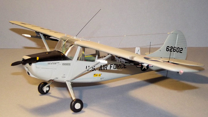 ides had differing structures which wanted
to bend to a different extent. I solved this problem by gluing the door shut on
the right hand side, eliminating any thoughts of displaying the finished article
with the door open.
ides had differing structures which wanted
to bend to a different extent. I solved this problem by gluing the door shut on
the right hand side, eliminating any thoughts of displaying the finished article
with the door open.
With the absence of locating pins on the fuselage halves I glued small tabs of plastic card to the inner edges to improve alignment .The fuselage halves were glued together and the two wing root ribs braced apart temporarily with wooden matchsticks trimmed to length. A smear of filler was needed along the fuselage joint line.
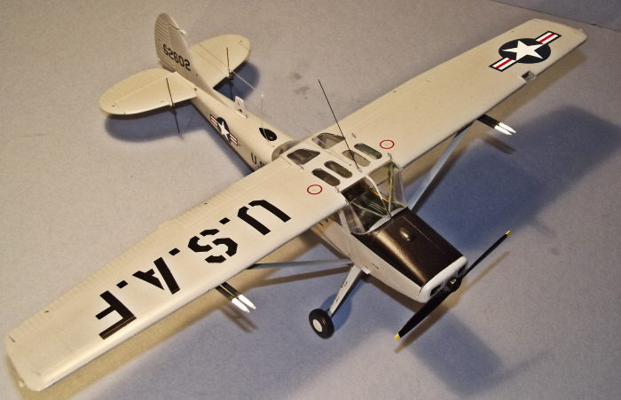
The assembly plan had also been complicated by the window arrangement that required the rear cabin side windows to to be installed from the inside, while the front and rear transparencies and the pilot’s side windows are fitted from outside. I installed the rear side windows and curved rear window assembly , not forgetting to glue in the diagonal bracing struts inside the rear window opening. Once dry this formed a solid and stable assembly for the upper cabin structure but as a precaution I glued in a section of plastic rod to the roof area just forward of the back-seater’s position, making sure that it would not show through the upper windows. This cross beam allowed the pilot’s seat harness to be secured at cabin roof level.
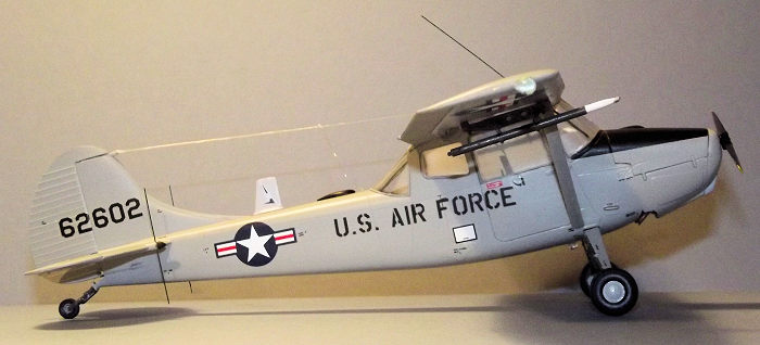
With all the trimming and fettling needed so far I had no confidence in my ability to accurately assemble the 25 part engine with its spider’s web of inlet and exhaust pipes and the fragile cantilever engine mount so I resolved that the engine parts would serve to support the exhaust pipes and propeller and little else. The whole unit was assembled and painted gunmetal grey then wedged into the nose area with small sections of plastic card. The cowling side and top panels proved to be well engineered and an accurate fit and were glued in place without fuss. The windscreen was trimmed and carefully glued into place.
The wing is a relatively simple structure with the upper surface in one piece tip to tip. The centre section windows proved to be as much of a fiddle as those to the cabin sides but eventually they were persuaded to fit. The left and right underwing panels were glued in place and there began a session of fiddling and fettling to get the wing to sit down on top of the cabin structure. After umpteen trial fits I was satisfied and the wing glued in place. The horizontal tail halves locked neatly onto the rear fuselage and the one-piece elevator assembly slipped in place, while noting that the right hand elevator has a trim tab. The rudder was tacked on to the rear of the fin, trapping a small bell crank which would be linked to rudder cables at the end of the build.
Main joint lines were cleaned up and I found the need for some filler along the fuselage lower joint.
| COLORS & MARKINGS |
Vinyl masks are not my
first choice when it comes to painting; I normally prefer a kabuki type mask
from a producer such as Eduard, but at the time of this build none were on offer
so the Montex version was put to use. For a very reasonable £6-50 the pack
provides five small sheets of accurately pre-cut vinyl, two of w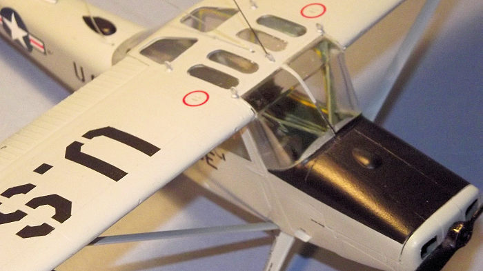 hich are in
Black and offer masks for the inside and outside of the glazing and wheel masks.
The remaining sheets are in a pale grey-green and simply offer stencils for the
same markings as those provided by Roden in decal form, essentially the national
markings, large arm of service lettering and airframe numbers. Airframe
stencilling must still come from the Roden sheet.
hich are in
Black and offer masks for the inside and outside of the glazing and wheel masks.
The remaining sheets are in a pale grey-green and simply offer stencils for the
same markings as those provided by Roden in decal form, essentially the national
markings, large arm of service lettering and airframe numbers. Airframe
stencilling must still come from the Roden sheet.
The Montex vinyl canopy masks were carefully applied and they fit well although they had a tendency to curl away at the edges overnight and need to be carefully pressed back into place before any paint is sprayed. I did not use the internal canopy masks. The airframe was primed in grey auto primer from a rattle can, then rubbed down with the finest grade of sanding stick that I could find.
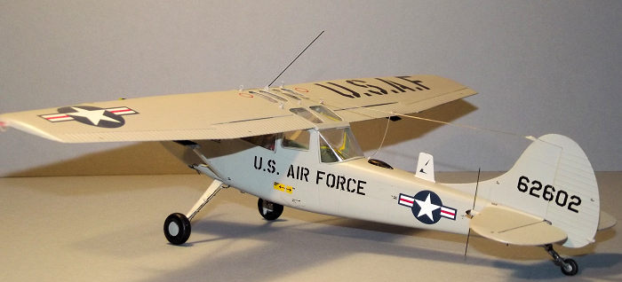
With my Iwata HP-C airbrush fired up the whole airframe was painted in Tamiya XF-80 Royal Light Grey. The “right” grey can be a source of much modelling heartache, being a colour that can change perceptibly according to the weather or the time of day, so Tamiya’s colour is just my choice of what seems to be right. The landing gear legs and wing struts were painted separately. (Editor's note: the 'proper' grey is FS 16473, formerly known as ADC Grey)
The airframe needed to be masked up for the Black anti-glare panel over the engine, so I took the opportunity to use the Montex masks for the U.S.A.F and U.S. Air Force titling. I do not have the confidence to mask and spray multi-colour national insignia but these mono colour subjects worked just fine and avoided any problems with decal film for these large titles.
The decals are rather thick and glossy but went on fairly easily once the airframe had been coated with Future/Klear applied as a varnish and only a little assistance was required from Micro Set deal solution. The airframe was finished with an airbrushed coat of Xtracrylix flat varnish.
 The fragile looking plastic
landing gear main legs and tail wheel assembly were replaced with equally
fragile looking cast metal items from Scale Aircraft conversions. The Bird Dog
is no lightweight so it remains to be seen whether scale thickness heavily
cantilevered main gear legs can resist the force of gravity long term – metal or
not. The thin section tail wheel leg collapsed under minimal pressure when the
aerials were being rigged and had to be strengthened with a strip of plastic
card epoxied along its underside. The metal parts are a straight replacement for
the kit items and easily fixed into place with a dab of super glue. The wing
support struts were glued in place and a half set of White Phosphorus target
marking rockets fixed to the inner pylons, while the outers were left empty.
The fragile looking plastic
landing gear main legs and tail wheel assembly were replaced with equally
fragile looking cast metal items from Scale Aircraft conversions. The Bird Dog
is no lightweight so it remains to be seen whether scale thickness heavily
cantilevered main gear legs can resist the force of gravity long term – metal or
not. The thin section tail wheel leg collapsed under minimal pressure when the
aerials were being rigged and had to be strengthened with a strip of plastic
card epoxied along its underside. The metal parts are a straight replacement for
the kit items and easily fixed into place with a dab of super glue. The wing
support struts were glued in place and a half set of White Phosphorus target
marking rockets fixed to the inner pylons, while the outers were left empty.
I do not normally add aerials but this is one dog that really needs its whiskers. Roden provides lengths of stiff wire for the antenna on the tail plane leading edges and the cabin top, a sure recipe for a poke in the eye when moving in for close work, so I replaced them with flexible soft bristles from a yard broom that I bought from my local pound store. The same bristles were used to represent rudder cables. The cabin to fin tip aerial came from stretchy nylon thread secured with super glue. Installation of the spine aerials, wing tip light covers and the propeller completed the build.
| CONCLUSIONS |
This is a good example of modelling with the heart and not with the head. I bought the box art and the rest followed. It cost more than I might have expected when I spent £35-00 on extras. The build took longer than I planned with the hours spent considering what, if anything, I could do about the rather basic interior within the limits of my skillset. The absence of instrument panel decals is an unnecessary niggle in a product that otherwise provides a good basis for a convincing model. Vague instructions and a fiddly break down of parts add to the challenge.
Roden has a reputation for kits that are reasonably well detailed but sometimes have a challenging fit of parts and this one seems to follow the norm. Maybe not for beginners, but an impressive model upon completion and recommended for fans of subjects from the Vietnam era.
| REFERENCES |
O-1 Bird Dog in Action by Al Adcock. Squadron/Signal Publications No. 87. Published 1988.
26 February, 2018
Copyright ModelingMadness.com.
If you would like your product reviewed fairly and fairly quickly, please contact the editor or see other details in the Note to Contributors.
Back to the Main Page Back to the Review Index Page Back to the Previews Index Page