| KIT #: | 48020 |
| PRICE: | $39.95 SRP |
| DECALS: | Sixteen options |
| REVIEWER: | Scott Van Aken |
| NOTES: | New tool kit |
| HISTORY |
The Northrop F-5A/B Freedom Fighter and the F-5E/F Tiger II are part of a family of widely-used light supersonic fighter aircraft, designed and built by Northrop. Hundreds remain in service in air forces around the world in the early 21st century, and the type has also been the basis for a number of other aircraft.
 The F-5 started life as a privately-funded light
fighter program by Northrop in the 1950s. The first-generation F-5A Freedom
Fighter entered service in the 1960s. During the Cold War, over 800 were
produced through 1972 for U.S. allies. The USAF had no need for a light fighter
but specifed a requirement for a supersonic trainer, procuring about 1,200 of a
derivative airframe for this purpose, the Northrop T-38 Talon.
The F-5 started life as a privately-funded light
fighter program by Northrop in the 1950s. The first-generation F-5A Freedom
Fighter entered service in the 1960s. During the Cold War, over 800 were
produced through 1972 for U.S. allies. The USAF had no need for a light fighter
but specifed a requirement for a supersonic trainer, procuring about 1,200 of a
derivative airframe for this purpose, the Northrop T-38 Talon.
The improved second-generation F-5E Tiger II was also primarily used by American Cold War allies and, in limited quantities, served in U.S. military aviation as a training and aggressor aircraft; Tiger II production amounted to 1,400 of all versions, with production ending in 1987. Many F-5s continuing in service into the 1990s and 2000s have undergone a wide variety of upgrade programs to keep pace with the changing combat environment.
The F-5 was also developed into a dedicated reconnaissance version, the RF-5 Tigereye. The F-5 also served as a starting point for a series of design studies which resulted in the twin-tailed Northrop YF-17 and the F/A-18 series of carrier-based fighters. The Northrop F-20 Tigershark was an advanced version of the F-5E that did not find a market, thanks to the meddling of politicians who removed advanced systems from the aircraft before allowing foreign sales. The F-5N/F variants remain in service with the United States Navy and United States Marine Corps as an adversary trainer.
| THE KIT |
The model community has long awaited a new tool 1/48 F-5A/B kit. True, there was a short run version produced by Classic Airframes and your editor built a couple of these, however, it was typical of the genre and required advanced modeling skills to complete. No longer as we now have a standard injection molded kit from the folks at Kinetic.
 The kit is designed in modular fashion, boding well
for a variety of F-5 types to be done in the future. Basically, the fuselage is
built in forward and aft sections with various inserts to take care of the
difference in the F-5As built for some places like Canada and the Netherlands.
The kit comes with complete intakes, a nice touch, though perhaps somewhat
difficult to built and eliminate the seam that runs down the length on both
sides.
The kit is designed in modular fashion, boding well
for a variety of F-5 types to be done in the future. Basically, the fuselage is
built in forward and aft sections with various inserts to take care of the
difference in the F-5As built for some places like Canada and the Netherlands.
The kit comes with complete intakes, a nice touch, though perhaps somewhat
difficult to built and eliminate the seam that runs down the length on both
sides.
There are separate control surfaces for the rudder, ailerons and flaps. The latter can be molded in the lowered position. A separate insert for the engine cooling doors used on Dutch and Canadian aircraft are included as are the additional upper rear fuselage cooling vents. Moving forward, there are separate speed brakes and another insert for the forward fuselage side and for the lower forward fuselage. The cockpit is well appointed with raised detail for the instrument panel and consoles. There are two different nose gear arrangements, again depending on if a standard F-5A or CF/NF-5A are being built. The canopy can be posed in the open position.
For the wings you can put Sidewinders or tip tanks on the end. I am not sure if the tanks are properly angled down or not as it is difficult to tell without building the kit. Under the wings are four pylons for Mk.82 slick bombs, rocket pods or drop tanks. Two different centerline tanks are also provided. Another inclusion is a small photo etch fret for the slime lights (when required) and vents.
The
instructions are a whopping 34 pages, though much of that is for the 16 markings
options and for the different construction sequences for the standard and
CF/NF-5 versions. There are three US options; two in silver portraying a
prototype and one with the 4441 CCTS. A third one is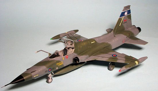 listed as being ADC Grey
with daglo patches flown at Kelly AFB while awaiting delivery to Greece. For
Canada there are three options. One is in the final 'glop' scheme in 1995 that
is stored with the Canadian Warplane Heritage. Then there is a 434 Squadron
aggressor that is displayed at the Canadian Aviation and Space Museum, also in
'glop'. The last one is a 434 Squadron plane in the green/grey wrap scheme of
1988. Moving on to the Netherlands we have two options, both with 315 Squadron
One in the original NATO scheme and one with the latter greys. Then we have a
pair of Norwegian aircraft in silver. One with 336 Squadrons as the Jokers
aerobatic team and
another with 334 squadron. Both of these options have
multiple serial/code choices. Then we have Greek planes with
five options. The first three are with 341 squadron; two in dark blue-grey over
silver and one in the latest 'glop' scheme. The Greek AF markings I have seen in
person and on slides are a much darker blue, but that is not to say the light
blue was not used. Next is an NF-5A with 349 Squadron in two shades of
light grey with the final scheme being another NF-5A with 343 Squadron, also in
a glop scheme. The final option is a South Vietnamese plane with 522 Squadron
in 1969. This one also has multiple serial choices.
listed as being ADC Grey
with daglo patches flown at Kelly AFB while awaiting delivery to Greece. For
Canada there are three options. One is in the final 'glop' scheme in 1995 that
is stored with the Canadian Warplane Heritage. Then there is a 434 Squadron
aggressor that is displayed at the Canadian Aviation and Space Museum, also in
'glop'. The last one is a 434 Squadron plane in the green/grey wrap scheme of
1988. Moving on to the Netherlands we have two options, both with 315 Squadron
One in the original NATO scheme and one with the latter greys. Then we have a
pair of Norwegian aircraft in silver. One with 336 Squadrons as the Jokers
aerobatic team and
another with 334 squadron. Both of these options have
multiple serial/code choices. Then we have Greek planes with
five options. The first three are with 341 squadron; two in dark blue-grey over
silver and one in the latest 'glop' scheme. The Greek AF markings I have seen in
person and on slides are a much darker blue, but that is not to say the light
blue was not used. Next is an NF-5A with 349 Squadron in two shades of
light grey with the final scheme being another NF-5A with 343 Squadron, also in
a glop scheme. The final option is a South Vietnamese plane with 522 Squadron
in 1969. This one also has multiple serial choices.
| CONSTRUCTION |
Right off the bat you have to decide which version of the F-5A to do. This is because you have to choose the correct inserts for the straight F-5A, CF-116A, or the NF-5A. This delayed the start of my build a bit as I had to figure out which to do. I finally settled on doing a CF-116A and so followed the instructions on building that variant.
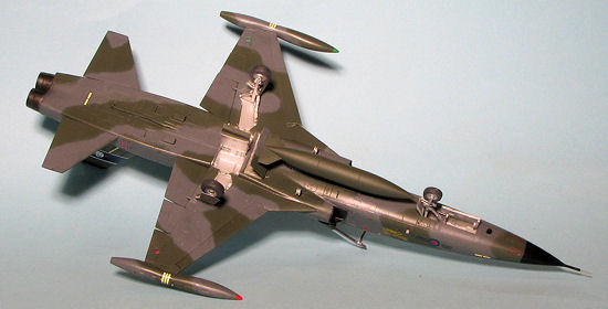
First thing I did was to cement together the centerline fuel tank and the wings. The Canadian aircraft used the pointed centerline tank so the other was left in the box. I also looked through a lot of photos to see how I wanted mine to be fitted. The majority of photos showed the aircraft with no wing pylons, carrying only the centerline pylon and tank. This makes some sense as the inner pylons and fuel tanks were usually only carried when making cross-country flights and the outer pylons were usually just for weapons, which, unless the unit was doing weapons training were generally not installed. This meant that I had some pylon holes to fill in the wings, which was done with super glue. I also cemented together the nose cone and then took care the seams on it and the centerline tank.
 I then built up the cockpit. The canopy mechanism is molded
in the open position and if one wants it closed, pieces need to be cut away.
This two piece assembly fits into grooves in the back of the cockpit. I did not
attach the inner canopy section at this time and found the assembly to be a bit
fiddly to line up. The control stick was glued in and the cockpit painted dark
gull grey using Testors enamels. The instructions call for a lighter aircraft
grey, but it seems darker than that. The seat was assembled and painted with Tru-color
NYC light grey, which is actually pretty dark, to give a bit of contrast.
I then built up the cockpit. The canopy mechanism is molded
in the open position and if one wants it closed, pieces need to be cut away.
This two piece assembly fits into grooves in the back of the cockpit. I did not
attach the inner canopy section at this time and found the assembly to be a bit
fiddly to line up. The control stick was glued in and the cockpit painted dark
gull grey using Testors enamels. The instructions call for a lighter aircraft
grey, but it seems darker than that. The seat was assembled and painted with Tru-color
NYC light grey, which is actually pretty dark, to give a bit of contrast.
Then I started on the fuselage inserts. Beginning at the rear, I glued the fuselage halves together then installed the exhaust sections. Just in front of the exhaust are two smaller inserts. Why these are separate is beyond me as they do nothing to help the fit, which is not exactly snug. The lower section was then glued in place. It should be pointed out that none of the joins were able to get away either without filler of having gaps larger than the engraved detailing. This is especially true of all the inserts, that are all smaller than the area they have to fill. The rear fuselage inserts are for the engine blow-by doors used on the CF and NF-5 airframes. A standard blanking plate is given for the regular F-5A. Two sets of doors are given; open and closed. These were only open if the engine was running so I installed the closed set.
At the nose section, there are two inserts on either side; again depending on the version you are doing. I installed the CF-5 inserts and while I was at it, opened up the holes for the refueling probe. Again, the inserts are too small. I then trapped the cockpit and the nose gear well in between the fuselage halves. Later, the nose section was glued on.
With the fore and aft fuselage done, I then turned to the intake assemblies. The kit gives full intakes to the first compressor stage, and there is a very long seam to fill if you want. However, even the flashlight crowd will have difficulty seeing it. Your choice, though. Fitting the intakes takes a lot of work and super glue to get them into something of a proper alignment. What I did was to install each side to the forward fuselage before the regular glue dried and then apply the super glue to hold them in place. Even then, I had to break out the filler. I then attached the wings to the aft fuselage section when that was dry, the forward section was glued in place. I had to use super glue on one side as the area behind the cockpit was narrower than the area on the aft fuselage section. This left an insert to go below the intakes. This piece did not fit at all well being wider than the space it had to fill. Much trimming was done to get this to fit. After all that, more filler was needed to take care of the gaps and the steps between sections. The leading edge slats as well as the ailerons and flaps can be lowered. An ingenious method of offering tabs for both raised and lowered surfaces is provided. One simply removes those not used and inserts them in the wing. This worked quite well and is really a great idea.
 I decided to let it sit for a bit while I worked on other
projects and when I came back to it, I started installing the various rear
fuselage intakes. The exhaust section was then attached. This consists of a
plate which already has one of the exhaust molded into it. The other was
attached and this assembly glued in the back. As there is a separate rear piece,
that goes just to the upper rear portion of the fuselage, the fit was not the
best. I am not sure why these pieces are separate as it makes no sense to me at
this moment in time. With the exhaust in, I started work on the wing tip tanks.
These are only slightly angled down when done so it is up to you to determine if
this is enough. Also, there is no really positive fit on these and only after
the kit was painted did I notice that one tank angles in a bit more than the
other. Those who want to have clear tip lights will need to do the surgery to
make those before gluing on the tanks. This kit also has etched slime lights and
no real marks on the kit as to where they go. Personally, I would have preferred
them to have already been molded in place and then told to sand them off if they
were not needed, but since it seems most of the kit markings are without them,
this is probably why this was done.
I decided to let it sit for a bit while I worked on other
projects and when I came back to it, I started installing the various rear
fuselage intakes. The exhaust section was then attached. This consists of a
plate which already has one of the exhaust molded into it. The other was
attached and this assembly glued in the back. As there is a separate rear piece,
that goes just to the upper rear portion of the fuselage, the fit was not the
best. I am not sure why these pieces are separate as it makes no sense to me at
this moment in time. With the exhaust in, I started work on the wing tip tanks.
These are only slightly angled down when done so it is up to you to determine if
this is enough. Also, there is no really positive fit on these and only after
the kit was painted did I notice that one tank angles in a bit more than the
other. Those who want to have clear tip lights will need to do the surgery to
make those before gluing on the tanks. This kit also has etched slime lights and
no real marks on the kit as to where they go. Personally, I would have preferred
them to have already been molded in place and then told to sand them off if they
were not needed, but since it seems most of the kit markings are without them,
this is probably why this was done.
The tail planes were next. Both of the attachment holes were reamed out a bit more to get them to fit. I then moved forward and installed the gun sight and a clear bit that fits into the sight. This clear bit did not attach well and went inside the fuselage where it is still rattling around, as there is no way to get it out. The windscreen was masked and glued in place, followed by a small etched bit in front. I then glued on the tail hook and the refueling probe. The cockpit was masked off to prevent overspray and I headed for the paint shop.
| COLORS & MARKINGS |
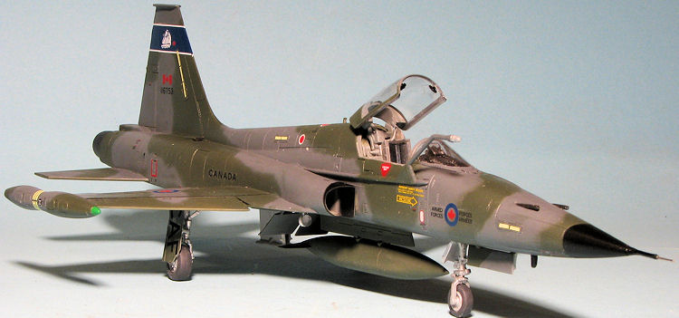
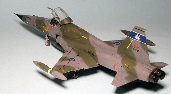
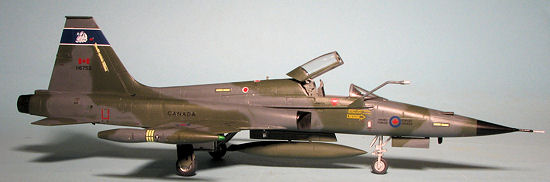
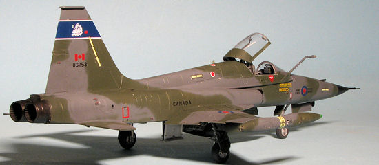
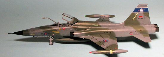
The scheme I wanted to do was the 434 Squadron option in Leading Edge's Sheet # 48-85. Not that the kit decals are not nice, as it really is, but I wanted to use these. Besides, I think the blue in the 434 squadron band is too close to black on the kit sheet. Anyway, this meant Testors enamels and I used RAF Dark Green and Dark Sea Grey for the two shades. But first, I painted the wheel wells, landing gear, and inside of the gear doors with Aluminum. The wells were then masked with tissue and I sprayed everything with the Dark Green.
 After a couple of sessions, the Dark
Sea Grey was applied. There is a disconnect between the upper, lower and side
views of this scheme on the sheet. Basically, do the side camo and then wing it
in terms of connecting the upper and lower sections. It will look fine once you
get it done. Be sure to get the gear doors and speed brakes as well during this
time. With the main paint on, I
returned to the bench to add the landing gear. Be sure to use the proper nose
gear for the CF-5A. It was at this time that I discovered, much to my disgust,
that I installed the nose gear well in backwards. Fortunately, the fit of the
nose gear is extremely tight so I was able to get it and the retraction strut in
place with minimal fuss. In fact, I had to sand a bit on the lower sides of
these pieces to get them to fit at all. With the gear in place, the entire kit
was sprayed with Future in preparation for the decals.
After a couple of sessions, the Dark
Sea Grey was applied. There is a disconnect between the upper, lower and side
views of this scheme on the sheet. Basically, do the side camo and then wing it
in terms of connecting the upper and lower sections. It will look fine once you
get it done. Be sure to get the gear doors and speed brakes as well during this
time. With the main paint on, I
returned to the bench to add the landing gear. Be sure to use the proper nose
gear for the CF-5A. It was at this time that I discovered, much to my disgust,
that I installed the nose gear well in backwards. Fortunately, the fit of the
nose gear is extremely tight so I was able to get it and the retraction strut in
place with minimal fuss. In fact, I had to sand a bit on the lower sides of
these pieces to get them to fit at all. With the gear in place, the entire kit
was sprayed with Future in preparation for the decals.
Since this is a jet, decals were not a short process. It basically took me the better part of two weeks, putting on a few, letting them dry, hitting them with Microsol, and letting that dry before moving on. I had no issues with the decals at all other than finding a couple were not numbered and there were decals that were not called for at all. The sheet provided enough markings to do at least two aircraft and perhaps three if one is careful with which insignia are used and uses kit stencils for some on the third option. I did find that the slime lights did not fit on the kit etched parts as they were too short. I used the kit light decals in this case.
| FINAL CONSTRUCTION |
 place. It
was now time for the clear coat over the airframe and I did so using a
semi-matte. When dry, I pushed in the clear wing and fin lights. The fin
light lens really needs to be installed when mating the fin halves together,
but then you will have to figure how to mask this tiny dot.
place. It
was now time for the clear coat over the airframe and I did so using a
semi-matte. When dry, I pushed in the clear wing and fin lights. The fin
light lens really needs to be installed when mating the fin halves together,
but then you will have to figure how to mask this tiny dot. 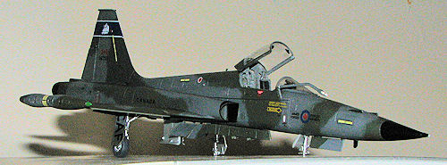 e
gear, breaking the refueling probe and knocking both the fuel tank and a
wheel of the MLG. I was able to piece back together all the bits, though I
never did find the tip of the pitot. I drilled a hole for a metal rod for
the broken nose gear and drilled the tip of the pitot for a small piece of
tubing. These were then reassembled and while not exactly perfect, will have
to do. A bit more touch up painting and I painted the tip of the tanks with
red and green. The wing lights got some clear red and clear green. The last
pieces were the landing lights, which can only be modeled extended. Had I a
pair of MV Products lenses on hand that would fit, I would have installed
those. I then quickly took the completed model to be photographed before any
other disasters could befall it.
e
gear, breaking the refueling probe and knocking both the fuel tank and a
wheel of the MLG. I was able to piece back together all the bits, though I
never did find the tip of the pitot. I drilled a hole for a metal rod for
the broken nose gear and drilled the tip of the pitot for a small piece of
tubing. These were then reassembled and while not exactly perfect, will have
to do. A bit more touch up painting and I painted the tip of the tanks with
red and green. The wing lights got some clear red and clear green. The last
pieces were the landing lights, which can only be modeled extended. Had I a
pair of MV Products lenses on hand that would fit, I would have installed
those. I then quickly took the completed model to be photographed before any
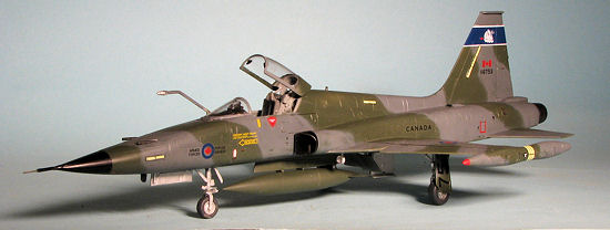
other disasters could befall it. | CONCLUSIONS |
Well, this was my first Kinetic kit and there were
things I liked about it and things that caused me issues. I liked the subject,
the ability to do several variants with one kit, the way the slats and flaps
were handled and the superb decal sheet. The multiple inserts and bits caused me
a lot of work and filler. I guess this is pretty much the norm for this kit as
others I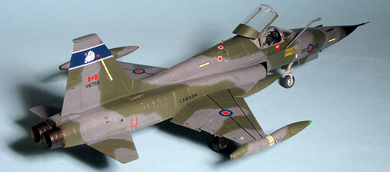 know
who have built Kinetic kits comment on how fiddly they are. Certainly they are
not kits that you can simply throw together.
know
who have built Kinetic kits comment on how fiddly they are. Certainly they are
not kits that you can simply throw together.
I think it fair to compare this to the older Classic Airframes kit. The previous kit used resin for the cockpit and some other bits and in those cases, the detailing was superior to what you get with Kinetic. Both of them are equally time consuming to build and both required more advanced modeling skills to complete. There were times when I found Kinetic's instructions to be a bit outside of logic. For instance, having the nose gear and door fully assembled before attaching the nose to the rest of the fuselage. However, those of us who have built a lot of model know that if we can, we will leave many of these bits off until later to prevent them from being damaged. Both kits also made into very nice models of the F-5A and I would give the nod to the Kinetic kit, as much for what it offers as anything else.
November 2012
Thanks to me for grabbing this one when it arrived at the LHS. Glad I did as they quickly sold out.
If you would like your product reviewed fairly and fairly quickly, please contact the editor or see other details in the Note to Contributors.