Trumpeter 1/32 F4U-4 Corsair
Page 2
Back to Page 1
On to Page 3
December 8
Today, much of my time was spent working on the engine exhaust. These are not the easiest pieces to clean up, but once they were mostly sanded and filed smooth, they were painted while still attached to the sprues. Once that was done, they were removed and installed on the engine, only taking them off the sprue one at a time. Though one would think that they'd be glued in place in a logical order moving around the engine, this is not the case so pay very close attention to the instructions to make sure that you don't get any in the wrong place. What you will end up with are four distinct groupings of exhaust; two pair and two single exhaust outlets. Once glued in place I repainted the areas that were attached to the sprues so they'd match the rest of the engine. I also gave the engine another wash with dirty thinner.
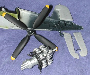 While the exhaust were drying, I installed the rudder onto the right fuselage half using superglue as recommended in the instructions. I'll eventually glue the rudder solid at some time later in the construction. I also assembled the two elevators at this time. Be very careful and don't mix up the two. Once the glue fully dries, I'll be sanding the join lines and using some filler. The kit sprue attachment points are really rather large and intrude quite a distance into the kit parts so require careful removal and clea
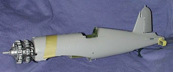 nup. I also finished painting the prop so that is now done.
The last thing done was to trap the engine in the fuselage and to cement the two halves together. I also made sure that the other side of the tail gear was glued solidly. The fuselage needed to be clamped and taped together to keep the joins good and solid. Next is more work on control surfaces.
December 9
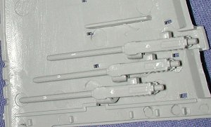
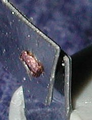 Today was spent working on control surfaces. As you probably know, the kit provides etched metal hinges through which one puts a steel rod then traps this between the two plastic bits. At least, that is how the ailerons and elevators work. The flaps, however, are more convoluted. One has to run a brass rod through several etched pieces, cut the rod, and then
 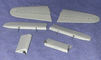 flatten the end. Looks good in the drawing; is a bit of a mess in reality. (see image to the left)
First off, the holes in the etched pieces are not large enough to allow the brass rod to go through them. This means that they must be drilled out slightly. Secondly, you are supposed to be able to squeeze the ends of the brass to flatten them so the parts don't fall off. I've not yet been able to do this successfully without making the brass ends look very messy and ragged. Perhaps I'll need to file these down later on. I had no trouble bending the bits that are supposed to be bent, nor was there any difficulty in supergluing them in place. However, it is slow work. I only managed to finish two ailerons, and two flap sections as well as installing the elevators into the horizontal stabilizers. I did get the fuselage putty applied and found a couple of more sink areas on the fin and elevator to fill.
December 11
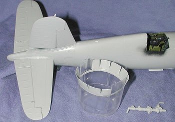
 Today, I did more work on the control surfaces. Basically assembling and sanding them in preparation for installation. Not a very exciting time and a bit tedious as I don't like doing this particular part of the build. Even though it is time consuming, it has to be done. I also worked on the wings. I'm building my Corsair with the gun covers closed. This means a couple of things. One is that I don't have to clean up the parts that I'm installing in the wings and it also means that I don't have to paint all the bits. I did put in the guns and will do the same for the belt trays and the belts so that I can see how they fit. I also want to see gun barrels when I look in the wing openings. That whole area will be painted flat black before gluing the wing halves together. It is just like the 109 except in this case the guns are actually hollowed out on the end. The shell ejector chutes are solid.
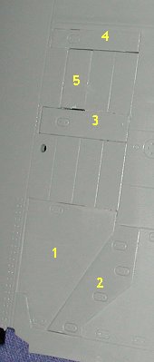
This also meant applying the covers to the upper wing. The fit on these is variable, which is a bit odd as you'd think they'd fit the same. Anyway, there are five covers on the upper wing. #1 fits quite well as it has a lip that runs around 3/4 of it to which one can apply glue. #2 has no lip to ride on so must be glued sort of 'up in the air'. Using liquid cement and a precision applicator really helps as I held it in place with a finger and applied the cement from the back.
Parts labeled #3 and #4 fit quite well, though they tend to sink down a bit too far so should also be nudged up to be level with the surface of the wing before the glue dries. You'll note that part #4 is a touch narrow so there is a gap. Part labeled #5 is a bit too short to bridge the gap between #3 and #4 so there will be a gap there no matter what you do.
I've had several questions on how long I work on this kit. Basically, it is an hour or maybe two when I sit down to the bench. Any more than that and I get to a point where parts or filler is drying and I really can't do much more than that. Now if you are a superglue builder (and there are some folks out there who use that material to build kits), then you can work as many hours on the kit as you want. However, I've not built any styrene kits using only superglue as I feel that cement makes for a more sturdy bond and is easier to work with.
December 12-14
 Spent much of this time working on other projects as the weekly builds take priority, but did get some more work done on the Corsair. The most visible of this was the installation of the tailplanes. It is impossible to put these on the wrong side as the tabs are different lengths. I also have a bit of a gap on the underside of the left tailplane that will need to be filled. I also attached the small actuators to the ailerons and rudder. The attachment points for a few of these are very large and require extra work to remove so all will be clean.
I also attached the cowl flaps to the cowling. These are quite thin in comparison with the rest of the plastic in the kit and are protected by some foam sheet. There are no ejector pin marks on it at all and it only leads me to wonder why the rest of the kit could not be similarly done. Due to its thinness, one has to be quite careful when handling it for cleaning and installation.
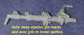 The last thing I worked on was the main landing gear. I started with just one to see how things would go. Well, it will take some work to get right. I'm not sure if others building this kit have run into this, but the lower section of the gear halves don't mate to each other once the lower strut has been glued in place. There is a rather pronounced gap that will need to be filled. The ejector pin marks on these parts are also rather prominent. The ones on the upper strut are rather deep while the ones on the lower section were raised. The latter were easier to clean up.
Copyright ModelingMadness.com. All rights reserved. No reproduction in
part or in whole without express permission.
On to Page 3
If you would like your product reviewed fairly and fairly quickly, please contact the editor or see other details in the Note to Contributors.
Back to the Main Page
Back to the Reviews Index Page