High Planes 1/48 F8F "Conquest I"
|
KIT # |
4805 |
|
PRICE: |
$40.00 |
|
DECALS: |
One aircraft: two variations |
|
REVIEW : |
Steve Mesner |
|
NOTES: |
Short run` |
|
HISTORY |
Darryl
Greenamyer’s N1111L “Conquest I” Bearcat is unquestionably one of the most
historically significant racing aircraft of all time. It was the most winning
Unlimited racer of the first decade of the Reno Air Races, 1964-1975, and was
the national champion in 1965, ‘66, ‘67, ‘68, ‘69, and ‘71. Today this historic
Grumman resides in the Paul Garber facility of
the National Air and Space Museum, awaiting public display at the upcoming
Museum Annex at Dulles Airport sometime (hopefully!) in the next decade.
Until now, if you wanted to model Greenamyer’s fast ‘Cat in 1/48, you had to
start with a Hawk/Testors or Hobbycraft Bearcat, sacrifice a Skyraider kit for
the propeller, a Mustang for the prop spinner, and then be prepared to do some
scratch-building, most notably of the Formula-1 type bubble canopy. (Various
conversion kits have been offered for sale over the years,
but I’ve never owned one and so can’t comment on them.) Australian limited-run
kit maker High Planes has changed all that with the release of three versions of
the famous racer.
This review will cover an out-of-box buildup of the second version of Bearcat
N1111L, “Conquest I” from 1969. At the same time I built this kit, my friend
Mark Gran built the third version, “American Jet” from 1975, adding aftermarket
parts and his own scratchbuilding touches. You can read his companion review by
looking in the Civil section. To avoid repetition, this full-build review will not duplicate information
included in my recent in-box review of this kit, which you can (and should!)
read here.
In order to understand some of my comments in both that review and this one
about different versions of this airplane, the following brief history of N1111L
from a modeler’s viewpoint might be helpful.
A VERY BRIEF HISTORY OF N1111L/CONQUEST I/AMERICAN JET
Grumman F8F-2 BuAer No 121646 was surplused in 1958. Unlike most surplus
Bearcats, which had their valuable R-2800 engines removed and were then
scrapped, ‘646 was one of a lucky few that remained intact and flyable. It was
originally registered as N7699C by Antelope Valley Aerial Surveys Co. of
Palmdale, CA. At some point the N number was changed to
N1111L. My references disagree on when Darryl Greenamyer came into possession of
the airplane. One reference shows a 1961 photo of the (mainly stock) Bearcat in
overall NMF with a simple N1111L on the rear fuselage, and says that Greenamyer
owned it at that time. An emblem of some sort on the cowling--which could be
Lockheed Flight Test--supports
this theory (Greenamyer was a test pilot for Lockheed). Another reference claims
that Greenamyer didn’t buy the Bearcat until a few months before first Reno race
in 1964. (In the information that follows, only major visual changes of interest
to modelers will be covered, not details of engine, systems, etc, changes.)
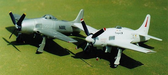 <<< High Planes Conquest I with model of “stock” N1111L, circa 1961,
which I built from a Hawk F8F-2 Bearcat kit in the late ‘70s. N1111L should be
red on the stock ‘Cat, not black. Note that the dorsal fin on the stock
Hawk/Testors kit is incorrectly shaped, being too large and too curved.]
<<< High Planes Conquest I with model of “stock” N1111L, circa 1961,
which I built from a Hawk F8F-2 Bearcat kit in the late ‘70s. N1111L should be
red on the stock ‘Cat, not black. Note that the dorsal fin on the stock
Hawk/Testors kit is incorrectly shaped, being too large and too curved.]
1964: N1111L stayed in stock condition until shortly before the ‘64 Reno race. It did have its stock canopy removed and replaced with a homebuilt low-drag unit made from the searchlight of a Lockheed Neptune. Squadron/Signal’s book F8F Bearcat in Action has a photo of N1111L as it appeared at Reno 1964. The picture is mis-captioned as 1966 but it is clearly 1964, as that is the only year the Bearcat carried the “Goldwater Elephant” cartoon on the cowling. The airplane still wore its bare aluminum finish. Greenamyer actually won one of the Unlimited races (scored under a complicated hydroplane racer points formula), but was disqualified for refusing to land at Stead Airfield as the rules specified, deeming the strip unsafe for the Bearcat’s landing.
1965: N1111L received most of its hallmark airframe changes for
the ‘65 race, including wings shortened to 27.5 feet with Cassidy wingtips, a
new Cosmic Wind (Formula 1) racer canopy, a larger propeller from an A-1
Skyraider, a prop spinner from a P-51H Mustang, and a tailcone “stinger.” The
flaps were deactivated and sealed up, and the spar reinforcing strip
under the wings was faired in with balsa wood and dope. N1111L carried a nearly
bare NMF to its 1965 National Championship victory at 375.10 mph. A painting of
the airplane as it appeared in 1965 can be seen on the
back cover of F8F Bearcat in Action (although the caption hints at a 1969
timeframe).
1966: No notable airframe changes, but the Bearcat received a white paint job
and the sponsorship of Smirnoff, along with which came trim in the form of blue
blunted arrowheads on fuselage and wings. High Planes sells a kit of the Bearcat
in these markings if you’re interested in building this version. N1111L captured
the National Championship at 396.22 mph.
1967: No airframe modifications and the paint job remained more or less the same
as 1966. There is a nice color profile of the airplane in its 1966-67 markings
in the old Aero book on the Bearcat, if you have or can turn up a copy. Again
N1111L was the National Champion at 396.62 mph.
1968: This year brought the next major airframe change, the large
fillets or strakes that blended the wing to the fuselage and faired in the wing
root at the trailing edge. The Smirnoff sponsorship was gone (apparently someone
decided that air racing and vodka might not be a good combination, for some
mysterious reason!) and with it the blue arrowhead graphics; N1111L
was returned to a very plain overall white finish. Again Greenamyer captured the
National Championship, this time at a slower 388.65 mph.
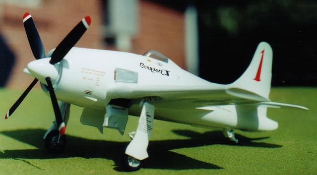
1969: The last major visual change in the airplane was made
before it set the world speed record (483.041 mph) on August 16, this being an
enlarged dorsal fin that bears a great deal of resemblance to that of a T-33
(recall Mr. Greenamyer’s long association with Lockheed). For the first time the
Bearcat bore the name “Conquest I” on its white finish, along with
sponsorship decals and crew names. This is one of three versions that High
Planes has kitted, and the subject of this review. Decals are included for both
the record attempt and the ‘69 Reno races themselves, which Conquest I handily
won at 412.63 mph. There would be no more major visual airframe changes in the
airplane until its retirement.
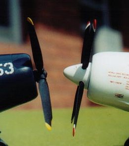
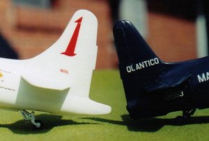 Fins of Conquest I and stock Hawk/Testors Bearcat. Caption: Note
enlarged, T-33-like dorsal fin fillet of Conquest I compared to stock
(corrected) dorsal fin fillet of F8F-2. Fin of stock Hawk/Testors kit is too
thin, dorsal fillet is too big. >>>
Fins of Conquest I and stock Hawk/Testors Bearcat. Caption: Note
enlarged, T-33-like dorsal fin fillet of Conquest I compared to stock
(corrected) dorsal fin fillet of F8F-2. Fin of stock Hawk/Testors kit is too
thin, dorsal fillet is too big. >>>
1970: For the first time since 1965, Greenamyer and the Bearcat
did not win Reno. Conquest I was still white, but my ref pics are unclear about
detail changes in the paint job from 1969.
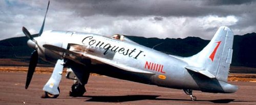
1971: Conquest I was back up to speed for ‘71, winning Reno again at a record
413.99 mph. Most of its previous white paint this year was covered with a silver
primer, though white still remained on the cowling and ailerons.
1972: Still in a simple silver paint job, “Conquest I” was painted in large
letters under the cockpit. The Bearcat did not win Reno this year.
 <<< Conquest I at Reno, 1972. (via Jack Bond)]
1973-1974: Apparently Conquest I did not participate in Reno
these two years.
1975: For its racing swan song, N1111L raced under the sponsorship of American
Jet and carried a snazzy new bright yellow paint job with bald eagle graphics.
After this race, the airplane was swapped to the National Air and Space Museum
and remains in this paint scheme to this day. High Planes also kits this version
of the Bearcat, which is built and reviewed by
Mark Gran in a companion review to this one; click here to read it and/or see
photos of AmJet. American Jet did not win Reno in 1975.
|
THE KIT |
Although the shape of the High Planes kit parts is very accurate, and the
surface detailing quite nice, there are no locating pins anywhere, leaving the
fit of major and minor parts alike pretty much up to the modeler. I’d strongly
recommend having a large, flat file on hand to true up the parts’ mating
surfaces, such as a Sears Craftsman 10-inch single-cut fine-cut mill file
(hereinafter referred to as the “big file”)--ask for it by name!
The sprue gates on this kit were huge, bigger than the sprues themselves on most
kits. I usually remove parts from sprues with a fine-cut Xacto razor saw, but if
I had done that with this kit, I’d still be working on it. I had to go buy a
medium-cut Xacto saw just to work on this thing and I’d advise you to do the
same. Your “big file” will also come in handy to remove the remaining sprue
nubs.
Also helpful will be brand-new sheets of 3M wet or dry sandpaper in 280, 320,
400, and 600 grits. Again, ask for them by name. I found epoxy putty and
superglue gel indispensable in making this model. Come prepared. Come very
prepared.
|
CONSTRUCTION |
WINGS
The wings seemed like a good place to start. Mark was able to start his American
Jet kit a few days before me and had already alerted me that the tops of the
gear wells had to be reduced to fit under the wing uppers, so I was ready for
that. However, I found that ALL the wing mating surfaces had to be flattened and
trued up first, which I accomplished with my “big file.” I also took this
opportunity to thin the trailing edges, tops and bottoms, down to a really sharp
edge. That all done, knocking the conflicting points of the tops of the gear
wells down was a simple matter; most of the conflict is in the front edge.
There are no locating pins, so mating was by shape and by matching the aileron
lines. The left wing mated up fine. On the right wing, the wingtip didn’t mate
up at all, with the upper rear tip being much shorter than the lower. Careful
comparison with the left wing was inconclusive as to which was “right.” I
decided that the right upper wing was a “short shot” and
added epoxy putty to rebuild the shape of the wingtip.
 Right wingtip
in process of reconstructive surgery. Barely visible in shadow of incompetent
photographer is the gray epoxy putty used to rebuild the rear part of the
wingtip.] >>>
Right wingtip
in process of reconstructive surgery. Barely visible in shadow of incompetent
photographer is the gray epoxy putty used to rebuild the rear part of the
wingtip.] >>>
The concave wingtips proved to be much easier to sand than I’d
anticipated. The radius was almost exactly that of a piece of sandpaper wrapped
around a standard Xacto knife handle. After I’d worked the epoxy-puttied wingtip
down to what I thought was right, I compared it with the “good” wingtip and the
puttied one was now notably longer! I guess the lower wing half had been too
long after all, not the upper too short. More sanding with the Xacto handle and
sandpaper eventually got both wingtips looking more or less the same. Still, I’m
glad that once the kit is assembled, you can’t see both wingtips at the same
time!
The oil cooler intakes in the wing roots need to be filled. The “right” way to
do this would have been to file some of the kit’s HUGE sprue plastic to shape
and cement it in, but I went the quickie way and just jammed a wad of epoxy
putty in there after the halves were assembled. Later, I filed and sanded the
putty to shape, then sealed it with a layer of CA glue. To finish
off the wings, I deepened the aileron lines a little with the back of a new
Xacto blade.
FUSELAGE HALVES
Before proceeding with anything to do with the fuselage halves, they need to be
trued up, i.e., the mating surfaces straightened and flattened. This can be done
with a big sheet of 320 sandpaper glued to plate glass, like a vacuform kit, or
as I did it, with the “big file.” Be careful in the tail area, as compromise
will be called for: The fin area is too thick and the “stinger” tail cone is too
thin. Work the fuselage down to the correct fin thickness, and you’ll lose most
of the tail cone and will have to rebuild it in some way. I elected to stop
sanding when the tail cone was as thin as I could stand it, and decided to live
with a slightly too-thick fin.
ENGINE
The kit’s “engine” consists of a disk with a big cylinder on it, around which
peek out the top quarter or so of nine cylinder heads. Don’t worry, you won’t be
able to see much of it when the kit is finished. The mounting for this “engine”
piece is extremely vague. I had to do some carving of the supposed mounting line
in both fuselage halves to get it to fit, and also
 some filing on the backing plate as well. I tried to get the thing centered as
well as possible, but as you can see from the photo, the engine is sitting well
off to the right of centerline. Oh well, at least I got it straight in both
“pitch” and “yaw,” which will be important later. I painted the whole engine and
inner cowlings flat black with a brush, then reinforced the engine plate
some filing on the backing plate as well. I tried to get the thing centered as
well as possible, but as you can see from the photo, the engine is sitting well
off to the right of centerline. Oh well, at least I got it straight in both
“pitch” and “yaw,” which will be important later. I painted the whole engine and
inner cowlings flat black with a brush, then reinforced the engine plate
with a big glob of epoxy putty, as I do NOT want this piece ever detaching
inside the fuselage, as there would be no way to recover from this.
<<< Note “engine” piece offset to right (left in the picture).
Fortunately, this will hardly show in the completed model.]
Were I
to build this kit again, I would assemble and sand the fuselage halves without
the “engine” in place, then cut off the cowling and install the engine inside
that from behind, using epoxy putty
 for placement. I especially recommend this
if you are planning to do something slick such as make your prop removable to
view the engine (aftermarket engine, of course!).
for placement. I especially recommend this
if you are planning to do something slick such as make your prop removable to
view the engine (aftermarket engine, of course!).
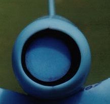
Speaking of the cowling, note in the comparison pic that the cowling is much
more accurate in shape than that of the Hawk/Testor Bearcat, which is in turn
itself a lot better looking than the cowling of the Hobbycraft Bearcat.
Cowling shape on High Planes Bearcat is more accurate than Hawk/Testor Bearcat,
which is in turn more accurate than Hobbycraft Bearcat. >>>
COCKPIT
As I planned to build my model with the tiny canopy permanently closed, I wasn’t
too worried about what the cockpit looked like. I assembled the kit’s seven
pieces (floor, left and right sidewalls, rear bulkhead, seat, instrument panel,
and joystick), truing things up as necessary with the “big file,” and just
painted everything Gunship Gray with a brush. The assembly looked a lot better
together than it did on the sprues, but if you want to display your canopy open,
you’ll probably want to replace the whole pit with something better, either
scratch-built, aftermarket, or from a Hobbycraft Bearcat. If you’re displaying
the canopy closed, you might as well leave the whole cockpit out and paint the
fuselage halves flat black, for all you can see of it
through the tiny glass.
Installing the cockpit was no piece of cake. There is no indication whatsoever
of where it goes, either in the plastic or in the instructions. I finally just
took my best guess, taking care only to make sure the floor was perpendicular to
the “edge” of the right fuselage half, into which I glued it with plenty of
liquid cement. This is another piece I don’t want coming loose someday, ever.
MATING THE FUSELAGE HALVES
At this point the fuselage halves lined up “pretty well” for mating. I used my
standard fuselage-building ritual of brushing two coats of (slow-drying) Testor
Liquid Cement on both halves of the fin and rearmost fuselage areas and mated
those together, making sure that cockpit, upper cowling panel lines, etc,
matched up, then taped the tail together tight overnight. The
next day, when the fin/tail area was dry, I wicked (fast-drying) Tenax liquid
cement into the rest of the fuselage joint, starting at the rear and working
forward. I then customarily bind the fuselage up with six or eight pieces of
masking tape to dry overnight. This usually results in a fuselage joint that
requires little or no filling, just knocking down the “squeezeout” with a file
and sandpaper.
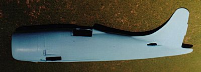 <<< Completed fuselage. Note “black hole” of cockpit area; this
entire area will be covered by the vacformed canopy--be careful when trimming
it!
<<< Completed fuselage. Note “black hole” of cockpit area; this
entire area will be covered by the vacformed canopy--be careful when trimming
it!
My right fuselage half had a crack in it that seemed to be the result of plastic
meeting from two sprue gates and not quite filling at their junction. I filled
this with a single layer of CA. The rear fuselage also had two indentations, one
on either side, that seemed to be deliberate, like handholds or vents or
something. One of these had an internal defect that I didn’t see any way of
fixing, so I simply filled both indents with CA and sanded them flush. Wonder
what they were supposed to be?
 The fuselage assembly actually went fairly smoothly. The Bearcat has one point
to watch out for, though: There’s a little ventral strake ahead of and behind
the tail wheel well. I thought I was going to lose this in the fuselage
straightening/sanding and Tenax gluing process, but it all survived--just
barely. I had a backup plan: If need be, I’d have removed the whole thing,
The fuselage assembly actually went fairly smoothly. The Bearcat has one point
to watch out for, though: There’s a little ventral strake ahead of and behind
the tail wheel well. I thought I was going to lose this in the fuselage
straightening/sanding and Tenax gluing process, but it all survived--just
barely. I had a backup plan: If need be, I’d have removed the whole thing,
cut a slot with a razor saw, and sanded out the slot to receive a strip of .020
or .030 styrene, which could be simply glued in and worked down to shape. Oh
yeah, you’ll need to open up the tail wheel well a bit, too. I used a Hawk/Testor
Bearcat model as reference for size/shape of this.
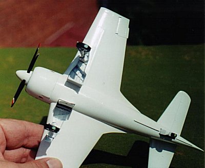
Underside of completed model showing ventral strake (fore and
aft of the tail wheel), LG wells, and wing strakes. >>>
STABILIZERS
At this point I customarily install the tailplanes, especially on aircraft where
they have no dihedral (which is most prop fighters). This way I can concentrate
on getting them level and perpendicular to the fin, and I can then use them to
help set the proper dihedral angle of the wings when it’s time to install those.
The horizontal stabilizers on this kit looked easy. The two parts cleaned up
nicely, and their location seemed clear from the indents on each side of the
fuselage. What could go wrong?
 The proper question would be, “What was I thinking?” Placed into their locating
indents, the stabilizers overhung the rudder joint line by about 3/32 of an inch
(remembering here; I didn’t measure it). In real life, this would be 4-5 inches
and would mean that the elevators would have kept the rudder from moving. This
is not a good thing! I solved this problem by hogging out the locating slots
completely through the fuselage and carefully extending them forward with a
rat-tail file until the elevator just cleared the rudder on each side. What
should have been a half-hour job at most consumed the better part of two whole
evenings of careful, painstaking, tedious work. And that’s not counting the next
evening, when I had to fill the created seam with CA and then sand it out.
The proper question would be, “What was I thinking?” Placed into their locating
indents, the stabilizers overhung the rudder joint line by about 3/32 of an inch
(remembering here; I didn’t measure it). In real life, this would be 4-5 inches
and would mean that the elevators would have kept the rudder from moving. This
is not a good thing! I solved this problem by hogging out the locating slots
completely through the fuselage and carefully extending them forward with a
rat-tail file until the elevator just cleared the rudder on each side. What
should have been a half-hour job at most consumed the better part of two whole
evenings of careful, painstaking, tedious work. And that’s not counting the next
evening, when I had to fill the created seam with CA and then sand it out.
CANOPY
I like to fit my glass before the wings go on; it’s just that much less material
to work around. After cutting the vacuum formed canopy out, it only took about
15 minutes of careful work to fit it to its opening in the fuselage--everywhere,
that is, but at the rear, where it didn’t want to sit down over the fairing
behind it. Not in the mood to file the fairing down at the moment, I tossed the
parts back in the box. The next day at work, it dawned on me that maybe the
canopy wasn’t supposed to fit over the fairing, but nestle down in front of and
flush with it. That evening I carefully trimmed away the forward edge of the
fairing, a thin sliver and a file stroke at a time, and guess what, the canopy
popped right down into a nearly perfect fit. The slick, cleanly molded canopy is
one of the best things about the whole model. I set it aside, to be mounted
again permanently just
before painting.
MOUNTING THE WINGS
I was dreading the work that would be involved in attaching the wings, as I’d
been messing with them throughout the build thus far and they didn’t even come
close to fitting. I could get the trailing edge into the recess in the fuselage,
or the leading edge, but not both at the same time. When the time came to
actually mate them up, I found that the interference was coming from the upper
portion of the root of the lower wing halves. Getting the wings into their
recesses was just a matter of carving and filing away the offending parts of the
lower wing halves. You can afford to take bold strokes here, as the cut-away
area will not show.
Getting the wings into their recesses was only the first half of the problem,
though, as they went in with no dihedral whatsoever. To get a bit of dihedral in
there, I had to scrape out the upper portions of the wing recesses in the
fuselage; I found an Xacto blade with the tip broken off to be the perfect job
for this. About 20-30 minutes of scraping on each side,
carefully test-fitting each wing along the way, did the trick.
Fitting up the wings actually went much smoother than I had
dreaded. I thought each would take a full evening of work but I managed to get
them both fitted and the right one glued on in a single evening. When the right
wing was dry, I mounted the left the next evening, carefully matching the
dihedral. Getting the dihedral right on Bearcats is a real challenge; only a
little too much or too little and the whole model doesn’t look right, and this
problem is aggravated with the short wingspan of Conquest I. At first I thought
I’d gotten just a skosh too much dihedral on the wings, particularly the right
one, but the finished model looks right, and that’s really all that matters.
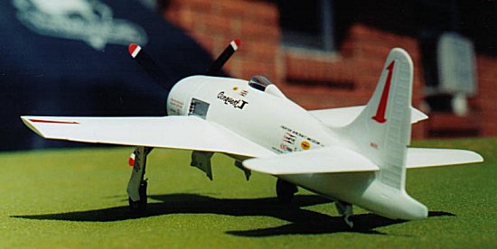
 The wing dihedral is
important to the look of any model airplane. Sometimes I think I got just a hair
too much on Conquest I, sometimes it looks right to me. >>>
The wing dihedral is
important to the look of any model airplane. Sometimes I think I got just a hair
too much on Conquest I, sometimes it looks right to me. >>>
WING FILLETS
The model was now looking like an airplane--like a Bearcat, even. Now I was at a
decision point. I had pretty much decided to do the model as the 1969 version of
Conquest I, using the kit decals, but if the kit’s wing fillet/strake pieces
(which were added to the real airplane n 1968) didn’t fit, I could file/sand the
extended dorsal fin (added in 1969) back to stock Bearcat contours and complete
the thing in a simple NMF scheme from 1965, as shown in the painting on the back
of the Squadron/Signal In Action book. As Mark had already regaled me with tales
of how much putty he’d had to use to get his fillets on, I was prepared for the
worst.
Again, I was pleasantly surprised. I took the kit’s instruction sheet at its
word and filed/sanded the surfaces that would meet with the wing and the
fuselage to a near-razor edge. That done, both fillets seemed to fit and mate up
remarkably well--on the topsides, anyway. (Tip: The rear portions of the fillets
sit a bit higher up on the fuselage than you’ll think at first that they should.
The strakes should run immediately under and parallel to the panel line on the
fuselage.) The undersides were another story.
I applied generous amounts of Testor liquid cement to the fillets, wing, and
fuselage and stuck them on, holding them firmly until the plastic was firmly
welded. The die was cast; there was no turning back from completing the kit as a
1969 or later version now.
The next evening, when the fillets were thoroughly dry, I started filling the
gaps between them and the wing and fuselage on the underside with Super Glue Gel
(Loctite, if you want the brand name). Wonderful stuff! It took three
applications, with each drying 24 hours before filing/sanding it down, to get
the job done. But the results were just what I was looking for. Meanwhile, I
sanded and blended the top surface of the fillets into the wing upper surfaces,
which also went smoothly. Except for a couple drops of superglue to fill cement
pinholes, I used no putty or filler on the topsides of the fillets or wings.
(Mark was amazed!)
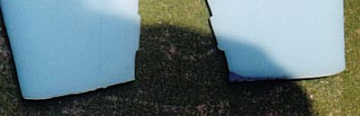
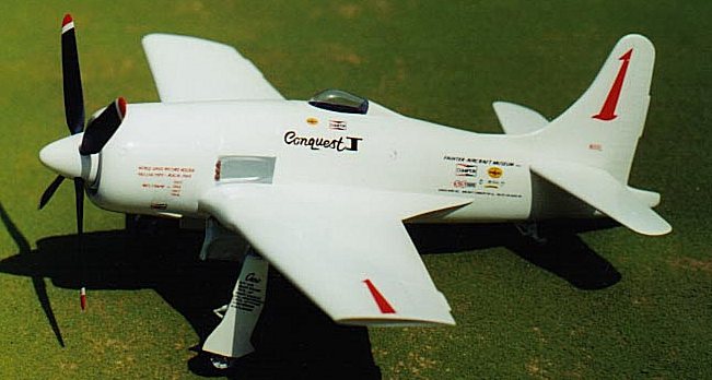
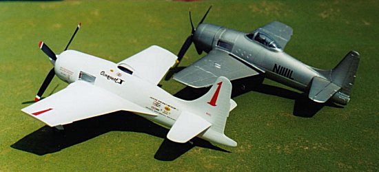 <<< This picture well illustrates Conquest I’s wing
fillets/strakes, as well as dorsal fin, tailcone “stinger,” clipped wings, and
other modifications from stock F8F-2 Bearcat (Hawk kit).]
<<< This picture well illustrates Conquest I’s wing
fillets/strakes, as well as dorsal fin, tailcone “stinger,” clipped wings, and
other modifications from stock F8F-2 Bearcat (Hawk kit).]
TAILWHEEL
The tailwheel, its strut, and its door are all molded as a single piece. This
looks a bit crude on the sprue but cleaned up fairly well, using a Hawk/Testor
kit part as a guide. I drilled out the lightening holes and cemented the part
into position with liquid cement on the door-to-fuselage seam, later reinforcing
the strut with CA gel where it contacted a mounting post on the inside of the
fuselage.
PAINT PREP
Now I mounted the vac canopy onto the fuselage with “odorless” (no residue) CA.
I masked it around its lower and rear edges with thin-cut strips of masking
tape, then filled in with liquid mask. As the landing gear bays in the fuselage
were open, I was concerned about airbrush overspray finding its way into the
cockpit area and onto the underside of the now-glued-on-canopy. I stuffed the
inside of the fuselage through the gear bay with a piece of plastic bag. (I was
going to stuff a piece of tissue or paper towel up there, but was worried about
lint getting on the inside of the canopy, too. Using the hunk of poly bag was a
last-second stroke of genius on my part--feel free to pirate this idea and use
it as you see fit in your next project!)
PRIMER
The model was primed in Model Master Dark Gull Gray for the simple reason that I
had a batch of it mixed up at the time. The primer showed a couple of minor
glitches to be fixed, which I did, and then reprimed with the Dark Gull Gray.
Almost immediately after priming, I was internet chatting with Alan Griffith of
AMTech and describing the project. “Prime it with Floquil Reefer White, it
covers great and is very smooth,” he said. This was an excellent idea.
Unfortunately, I didn’t have any on hand, and I wouldn’t be where I could buy
any for another week, and I wanted to get started painting the next
day. As things turned out, I’d have probably saved time to have waited the week
and gotten the Floquil paint.
PAINTING
I airbrushed the model with Model Master Classic White from the car line (a very
white white), cut with Walmart lacquer thinner, a combination that has worked
well for me in the past on model cars. I’ll spare you the details, but to make a
long story short, it took me seven coats to achieve a finish I could live with.
Later, after I’d had a chance to get some Floquil Reefer White, I primed the
gear doors, spinner, and prop tips with that and was able to get satisfactory
coverage with the gloss Classic White in just two coats. I did not want to clear
coat the model, as clear over white wouldn’t have looked particularly realistic
for this job. When the white was dry, I masked off the exhaust panel sheet metal
and airbrushed that in Floquil Old Silver.
When all the paint was dry, I ran a sharp Xacto blade around the
edges of the tape masking the canopy to prevent the tape from pulling the paint
off the vac plastic. This worked great and I have a nice clean masked line
around the cute little canopy.
PROP AND SPINNER
While waiting for the various coats of white to dry, I moved on to the other
detail parts. The two-piece spinner didn’t mate up well in contour, and to make
matters worse, the four prop holes didn’t line up, and were too small for the
prop blades. I glued the two spinner halves together solid, filed and sanded
them into a smooth curve, and drilled the blade holes larger and all the way
through. The prop blades themselves weren’t much fun to clean up, and a couple
of them had a nasty curve that had to be carefully de-bowed out.
After I was sure that the blades would go into the spinner properly, I primed
the spinner, its cylindrical backing plate, and the prop tips with Floquil
Reefer white. The spinner and backing plate then got two coats of Model Master
Classic white, which gave a nice finish. (I also painted the gear doors at this
time.) I cut some strips of masking tape to 1/16 inch and used these to mask the
stripes on the prop tips, then airbrushed the tips themselves red. (When
finished, the white stripes look too thick
compared to photos of the real airplane--I should have gone for 1/32 inch.) The
instruction sheet calls for the prop blades to be painted a medium blue similar
to PRU blue, but the photos I had of the airplane in 1969 seemed to show the
blades in black, or at least a much darker shade. (1970 photos, however, seem to
show the prop blades in a lighter shade.) I
went with my gut and painted the blades black. But because I eventually glued
the blades in place with white glue, I can remove them and repaint later if it
turns out I went the wrong way. I can fix the white stripes then, too.
LANDING GEAR
The metal landing gear cleaned up easily with an Xacto blade. The metal is quite
soft and easily bent with too much pressure. Careful here! I didn’t even paint
the struts themselves, just scraped the frosty surface off the oleo portions for
a chrome-like appearance.
WHEELS/TIRES
The detailing on the kit’s two-piece wheels looked soft, so I sharpened up the
wheel/tire demarcation with the back edge of an Xacto blade. Mark had warned me
by this time that the tires were too fat for the landing gear; the outer gear
doors would not fit correctly against the struts themselves. He was about to saw
his wheels in half and thin them when I suggested that he try the skinny wheels
from a Hawk/Testors Bearcat, if he had one on hand. He did and reported that
this worked for him like a champ.
Because I personally can’t stand the too-skinny Hawk/Testors wheels, I went a
different way. Before gluing the wheel halves together, I filed them a bit
thinner in the cleanup. Then, because the wheels themselves protruded a little
from the tires, I carefully inlet the lower gear struts into the wheels
themselves, stopping just short of having the strut touch the tire. I also
filed back the inner surface of the strut a bit to tuck the wheel further under
the strut.
All this work helped a little but didn’t completely solve the problem. When
mounted, my outer gear doors still stick out a little, like a P-51’s, instead of
laying flat against the struts as they should. I don’t lose a lot of sleep over
this.
DECALS
In researching the markings, I’d discovered that the placement of the big red
racing number 1s on the fin was slightly--OH so slightly!--different between the
left and right sides. “Ha,” I thought, “I’ll bet High Planes missed that!” I
could hardly believe it when I saw that the decal placement drawings on the
instruction sheet DID have that difference! After that, I just put my photos
away and relied on the kit instructions for decal placement. I was actually
looking forward to decaling the thing. The markings would bring the all-white
model to life, and Mark had told me that he’d just applied the colorful bald
eagle decals to his High Planes American Jet Bearcat model with no problems
whatsoever.
Well, good for him, but it didn’t work out that way for me at all. I started
with the big red number 1s on the fin, figuring if those gave me problems, I
could remove them and finish the kit in the record attempt markings, rather than
the race markings (Conquest I carried an American flag on the fin for the
record, rather than its race number). The decals wanted to stick
wherever they were first placed, although I’d carefully wetted the surface with
Testors Decal Set. Both fin decals split into several parts while I was getting
them placed, but I finally did get them where I wanted them.
Next came the “Conquest I” name under the left side of the cockpit, which also
gave me problems. I barely got this one in place before it broke up, and in fact
if you look carefully at the photos, you’ll see that I lost the lower right
serif of the I in “Conquest I” on this decal. I was even less lucky with the
right side-name decal, which simply didn’t survive its transplantation.
The sponsor decal for the left rear fuselage came next, and it was also died on
the operating table. This pretty much ruined my evening, as you can imagine.
Resisting the urge to Frisbee the model against one of my concrete block
basement walls, I hastily applied the upper and lower wing race number 1s, then
put the whole mess back in the box, came upstairs, got on the internet, and
bitched and whined and commiserated about my bad luck with ‘net friends for the
rest of the night.
The next morning, things looked brighter. I applied a thin layer of MicroScale
Superfilm with a Q-tip (a new one is always clean, and you just throw it away
when finished!) to the remaining decals, and applied the decals to the cowling
and the landing gear. I had to 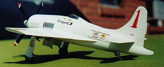 cheat and use the right-side sponsor decal for
the rear fuselage on the left side--the sponsor emblems are “handed,” right and
left, but would you have known if I hadn’t told you?--in order to get enough of
the model done to take the photographs. The Superfilm gave the kit decals JUST
enough strength to survive their application, and they’ll have to do until I get
replacements.
cheat and use the right-side sponsor decal for
the rear fuselage on the left side--the sponsor emblems are “handed,” right and
left, but would you have known if I hadn’t told you?--in order to get enough of
the model done to take the photographs. The Superfilm gave the kit decals JUST
enough strength to survive their application, and they’ll have to do until I get
replacements.
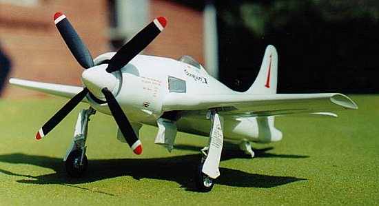
I had to use the right rear fuselage sponsor decals on the left side, and notice
that I lost the lower right serif on the “I” in “Conquest I." >>>
FINAL ASSEMBLY
Final assembly of Conquest I was relatively quick and painless. The exhaust
pipes were painted with Rust and flat black, and the tailwheel tire was painted
black. I glued the inner landing gear doors in their down position, and even
though you can see right through the fuselage, I have a picture of the real one
where you can see right through it, too!
The metal main gear legs with wheels already attached were cemented into the
wells with superglue, care being taken to get them vertical from the front and
aligned in profile. As soon as they were dry, I placed the model on a smooth
kitchen counter top and dragged a fresh sheet of 320 sandpaper under each main
wheel, one at a time, holding the model by pinching the wheel and strut for
strength. This gave me a perfect flat spot on each tire--try it on your next
project!
All that remained was to attach the main gear doors and the prop/spinner, both
of which I did with Elmer’s (common white) glue. Yes, I glued the prop solid,
but with an easily removable adhesive, as I’ll probably want to remove it
temporarily to apply the new decals, if and when I ever get them. At that time,
I might have a fit of industry and fit the prop up with a shaft made of aluminum
or brass tubing so it can spin. But meanwhile, I’m pleased to see that the
spinner covers so much of the cowling opening that you cannot see how far offset
the engine is in the cowling, just as I had suspected.
|
CONCLUSIONS |
I’m not a guy who whines if a kit’s not a “box-shaker.” I’ve been modeling for
more than 40 years and can remember when the Monogram Avenger was “state of the
art.” This was the first limited-run kit I’ve ever built (or, to tell the truth,
even gotten very far with), and
I don’t mind telling you it was a challenge. Many times as Mark and I built the
High
Planes Bearcats, we speculated on whether it would be more or less trouble to
convert a Hobbycraft stock Bearcat into Greenamyer’s racers than to build these
kits. My own estimate is that if you had a spare P-51 spinner and Skyraider prop
laying around, and the capability of making your own vac canopy, the total
effort involved in the conversion would be no more, and possibly a good deal
less, than building the High Planes kit. (I have somewhere between 40 and 60
hours in mine--I didn’t keep count.) But you still wouldn’t have the decals.
The
finished Conquest I looks great on my shelf along with the six Hawk/Testors
Bearcats I’ve built over the years, especially next to the one I built in its
“previous life” as the stock NMF N1111L. Now that it’s done, I feel like women
must feel about childbirth--I’m so proud of the finished product that the pain
of its creation recedes unless I really choose to remember it. Would I build
this kit again? Yes, I would, in a different marking variation this time,
probably the silver ‘71 scheme, or the no-strakes NMF ‘65. Having done it once,
I now know all this kit’s little tricks and glitches, and I hope that Mark and I
have passed enough of them along to you in our reviews to make your own
construction of the High Planes Bearcats much easier than ours were. Still,
though, were I to do it again, I would seriously consider getting a Hobbycraft
kit and bashing the High Planes cowling, upper and rear fuselage, and wingtips
onto it. Hobbycraft Bearcats are available under $15 if you
shop around, and that’s not a bad price for a “conversion set” these days. It
all depends on whether you want to spend $40 or $55 on your racing Bearcat, and
what your time and sweat are worth to you. Something to think about.
Special thanks go out to High Planes, who supplied the kit for review; Tom
Cleaver, who arranged for me to build the kit; Mark Gran, who, usually being a
few days ahead of me in most areas during our dual build, was able to pass along
valuable tips on what snags I had coming up next; and Scott Van Aken, who has
waited patiently for this review long, long past our original estimates.
Gentlemen, I’d be proud to work with you again any time!
|
REFERENCES |
The Making of Conquest One,” Peter Garrison, Air
Racing/Aerobatics, an Annual by the Editors of Flying Magazine, 1970 Edition,
Ziff-Davis Publishing 1970.
Gentlemen, You Have a Race: A History of the Reno National Champtionship Air
Races 1964-1983, John Tegler, Wings Publishing, 1984.
Racing Planes and Air Races, 1969, 1971, 1972, 1973, 1976 Annuals, Reed
Kinert, Aero Publishers Inc., 1969, 1971, 1972, 1973, 1976.
F8F Bearcat in Action, Charles L. Scrivner, Color by Don Greer,
Squadron/Signal
Publications Aircraft Number 99, 1990.
Grumman F8F Bearcat, Edward T. Maloney, Aero Publishers Inc. Aero Series
Vol. 20, 1969.
Copyright ModelingMadness.com. All rights reserved.
If you would like your product reviewed fairly and fairly quickly, please contact the editor or see other details in the Note to Contributors.