| KIT #: | ? |
| PRICE: | $70.00 |
| DECALS: | Two options |
| REVIEWER: | Scott Van Aken |
| NOTES: | Short run full resin kit |
| HISTORY |
A closed wing is a non-planar wing surface concept. The term "closed wing" encompasses the annular wing (better known as the ring wing), the boxplane, and the joined wing. Spiroid winglets are a closed wing surface attached to the end of a conventional wing. Closed wing designs are in a sense the maximum expression of wingtip devices, which aim to eliminate the influence of the wingtip vortices which occur at the tips of conventional wings. These vortices, which are a major component of wake turbulence, are associated with induced drag, which negatively affects aerodynamic performance in most regimes. The elimination of the aircraft's wingtips, and thus the great reduction or total elimination of wingtip drag has great implications for the improvement of fuel efficiency in the airline industry.
A closed wing surface achieves the minimum possible induced drag for a given lift, span, and vertical extent, and in some cases a span efficiency greater than 1. However, there is no particular advantage to the design; despite a decrease in local loading on any given point on the wing, the circulation is constant, thereby causing no change in the wake, and thereby the lift and interference drag associated with the surface.
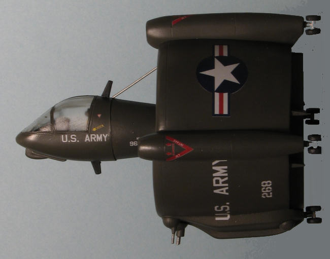
The most unique proposal in the AAFSS (Advanced Aerial Fire Support System) competition came from the San Diego division of Convair. The Model 49 did not fit the normal mold for either an airplane or a helicopter, and represented something entirely new. Propulsive power came from turbine engines driving counterrotating propellers within the shroud. Convair believed that the system was inherently more reliable than a conventional helicopter, and pointed out the only pilot control inputs involved directional control and setting rotor blade angle and engine speed. The crew of two occupied an articulating capsule on top of 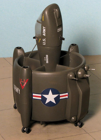 the shroud and was provided with a full array of sensors. The engines, fuel, crew capsule, and avionics bays were equipped with dual-property steel armor for protection against 12.7-mm projectiles. As a note, this particular competition was won by the AH-56A Cheyenne and was such a disaster that a second competition was held, one eventually won by the AH-64A Apache.
A wide variety of weapons were proposed for use on the vehicle. The normal complement included two side turrets with either XM-134 7.62-mm machine guns or XM-75 40-mm grenade launchers. Each turret was provided with either 12000 rounds of 7.62-mm ammunition or 500 40-mm grenades. A center turret carried an XM-140 30-mm cannon with 1000 rounds of ammunition. The center turret could also mount 500 WASP rockets, or a second 30-mm cannon. Each of the turrets could rotate and elevate and was capable of being fired while sitting on the ground, in a hover, or during high-speed forward flight. Mechanical stops were provided that prevented any of the weapons from firing at the nose of the crew compartment when it was articulated forward/down. Four hard-points were located on two of the engine nacelles; each could carry a fuel tank, three BGM-71 TOW missiles, or three Shillelagh missiles. Alternately, one of these hardpoints on each nacelle could carry a single M40A1C 106-mm recoilless rifle and 18 rounds of ammunition. The 106-mm cannon had an effective range of 10000 yards, and was effective against hardened targets. All of the hard points could rotate so that they could be oriented into the wind during high-speed flight, or aimed while being fired from either forward flight or a hover. Four external fuel tanks provided up to 1200 gallons additional fuel for ferry flights.
The mission modes for the Model 49 are shown above. The shrouded-rotor vehicle was capable of vertical takeoff and landing, just like a helicopter, and was also capable of hovering. The propulsion system consisted of three shroud-mounted Lycoming LTC4B-11 turboshaft engines, although the General Electric T64, Allison T56, and Pratt & Whitney JFTD12 were also investigated. The engines were coupled through clutches, shafting, and gear-reduction units to contra-rotating variable pitch rotors within the shroud. The thrust and lift systems were extremely interrelated, and the shroud amplified the thrust under some conditions, compensating for the relatively small diameter of the rotors. The engines and gear boxes were located in three of the nacelles along the sides of the shroud; the fourth nacelle contained the weapons and avionics. The overall control system was thought to be similar to conventional helicopters except for the removal of the cyclic pitch feature. Convair planned to leverage the experience gained during the Navy XFY-1 Pogo program in the areas of vertical control systems and power plant installations, and believed the development risk was minimal.
| THE KIT |
Fantastic Plastic is one of several companies that relies on Anigrand to produce their kits. That being the case, all the attributes of an Anigrand kit can be transferred over to this one. It is nicely molded, as are all Anigrand products, with the usual flash, resin pour stubs and other anomalies that will need to be cleaned up before assembly. Though the shroud has resin pins, on my kit, many of them were short shot so will need to be replaced with pins if o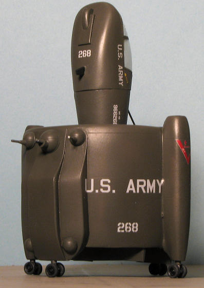 ne so desires.
The kit is somewhat complex compared to some and that is due to the arrangement of the engines, gearbox, counter rotating prop and the need for bracing within the shroud. There is a well appointed interior (for a resin kit) consisting of seats and control sticks. I do wish that these kits would include at least a decal instrument panel and while having belts molded on the seats is fine, I think that decals would work equally well if not better. This is due to the somewhat cloudy cockpit canopy. This clear resin part may be able to be cleared up with some polishing, but really, it could have been molded a bit better in terms of clarity as I've seen it done with other resin kits.
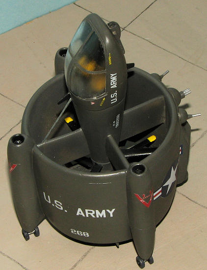
The cockpit section has two positions. One is where it is horizontal with the ground with the rest of the airframe vertical. This is how it would normally appear when not being flown or when being maintained or used in ground support mode. For flying and perhaps for static display at air shows, the cockpit was vertical to the airframe. For the horizontal mode, a piston is shown. A section of soft wire is included in the kit.
If one is wondering how to get all that stuff into the shroud, basically, one builds up all the pieces that go in there into the half shroud piece. Then the two other shroud sections are fitted and one goes from there. It seems to be well engineered and once all the parts are cleaned up, should build well.
Instructions are well done with photos to show where all the bits fit into place. The images are a tad small for these old eyes, but they are effective. JBOT makes the decals. These are ALPS printed with a single carrier and are prone to easy damage so coating them is recommended. The decals are nicely printed and in register. I do wonder at just how opaque the white will be as they are somewhat faint on the sheet, but will withhold judgment until I have a chance to try them. I'd recommend that the white on these sheets be double printed to remove any problems with transparency. Another option would be to provide two sets of white markings so one can double them up.
| CONSTRUCTION |
Anigrand produced kits can vary in terms of the quality of the molding and this one was not on the high end of the scale, with quite a lot of pin-holes and small voids. There were also some areas of mold misalignment (the engine pods) that needed sanding down (opening even more pin-holes) and filler. Doing all this prep work took me about a month. Of course, that was not solid work, but a little bit each day until the parts were properly treated. Even then, there are some that refused to cooperate and were just left for paint to fill in.
I should also mention that every alignment hole had to be drilled out more and in most cases, the pins that fit into them were either not there or very large and required sanding down. One reason why the tag "experienced modelers" is on the box.
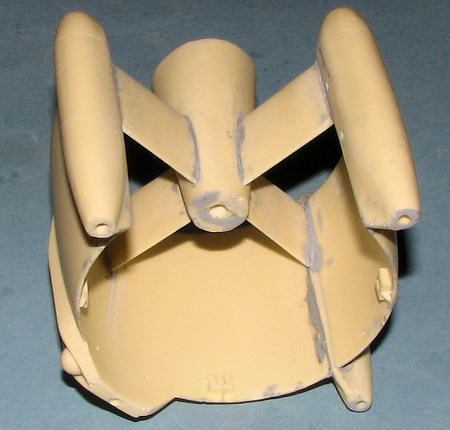 The instructions would have you build up the prop and the central housing with its braces first, then attach the motor pods and then attach the shroud parts. Naturally, I deviated from this by building up the central housing, then attaching the motor pods to the large front piece and then sticking in the central housing. It seemed to me to be a 'six of one, half dozen of the other' sort of thing. When building the prop assembly, I had the blades angled opposite each other in the two sections. I figures that the last thing needed by this sort of aircraft was a lot of engine/prop torque and they'd have done contra-rotating props anyway. I left off the prop assembly until after the shrouds were glued in place to kep it from being broken. Then, once the shroud pieces were on and I had a chance to fill and sand the joins (something you have to do on all of them). I then test fit the prop assembly. The hole for the shaft is not deep enough nor large enough so it was more motor tool work. I then glued on the prop. This was major mistake #1.
You see, though one is not told this, the prop hub has to be aligned just so in order to facilitate the major lower cross braces. I'd not taken that into consideration and had to snap of the prop to realign it for the braces. The large cross braces fit snugly into mounts molded on the inside of the shroud. I did not glue the prop assembly until both large braces were firmly in place. Having snapped off the prop shaft removing it, I aligned things as best I could.
Once that was done, I glued in the braces, flat side down as indicated in the instructions. It is a tight fit to say the least. Then I started to install the small cross braces. Major mistake #2. The instructions do not tell you that the alignment holes for these small braces need to face a certain direction. Actually, this may make no difference as I eventually sanded off the alignment pins when they were glued in place.
At this time, I felt it would be appropriate to work on the cockpit area. This is because I'd need to have things pretty well painted before continuing.
The cockpit area has two sticks and two seats. Naturally, the sticks are very thin and I managed to break both of them cleaning them up. The seats were not completely molded, one of which had the bucket part canted off about 20 degrees to the right. Fortunately, the clear canopy is not very clear and I doubt anything can really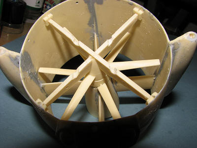 be seen besides just vague shapes. I painted everything black with the seat backs in a tan just to show there was something in there. Though thick, Anigrand's transparencies have engraved framework. This makes masking very easy indeed and one just follows along the engraved areas when cutting tape. The fit of the canopy was very good as well requiring only a bit of sanding to get to fit. It was glued in place using gloss clear acrylic paint (Vallejo).
Before painting, I test fit the large exhaust vanes. This found Major Mistake #3. They were no where near their alignment holes. The large cross braces jutted down too far for a proper fit. I ended up grinding slots in the large cross braces to get the large vanes to fit properly. This also had to be done to the small cross braces so the small vanes would fit. As things were assembled, the small vanes were too long so it was cut them short or grind slots in the small braces. I chose the grind option. The only way I can see to get the large vanes to install properly is to move the large braces about a quarter inch higher in the shroud from where the attachment points are located. But that would throw off everything else as well. The grinding option seemed to be the easiest and that is the one I took. Fantastic Plastic has been kept informed of all this so they can look into it. I must have done something wrong as they reported to me that they did not have this problem when the build for the instructions was done.
| COLORS & MARKINGS |
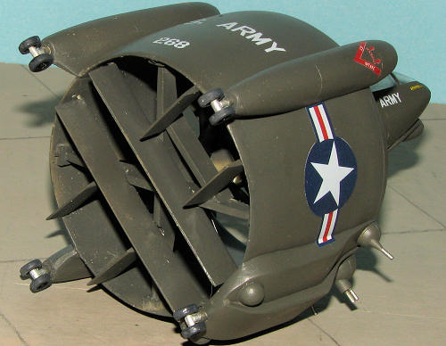 Now that the major assemblies were together and dry, I took them and the exhaust vanes to the paint shop. Color for this is simple. I used Testors Helo Drab enamels with no undercoat (mainly because I'd sanded every square inch already so no problem with residue). It takes more than you'd think to cover.
Once done, I hand painted the prop blades black with yellow tips. It was not as difficult as it might seem to paint as the lower prop section was free to spin to where I could easily get to it.
| FINAL CONSTRUCTION |
OK, now it was pretty well painted. Next step was the landing gear. The kit provided a spare gear leg which wasn't needed. After the usual clean up, the mounting holes were drilled larger and the legs glued in place. I glued mine vertical to the plane of flight. I thought that if this thing were to touch down to fire its guns. It wouldn't want the recoil to be moving it backwards on its wheels. Having the wheels turned the way they are would provide some resistance to the recoil.
The gear axle isn't perpendicular to the strut so I knew there would be some wheel sanding at the end. The wheels are pretty much out of round in terms of wheel/tire so I painted the hubs gloss black Using Gunze Mr. Color lacquer so the disparity wouldn't be as noticeable. Then the tires were painted Weathered Black from the Floquil range. Once the wheel hubs were drilled out to fit the axles, they were installed. Interestingly, I did not have to flatten them as much as I'd feared.
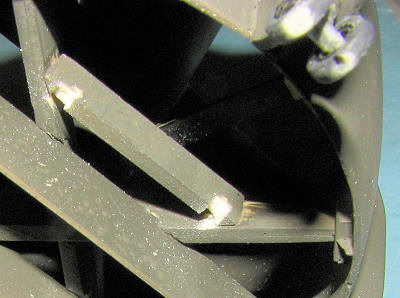 I then took the opportunity to glue in the large and small vanes using the notches I'd cut. You can see the notches cut in the small braces. It all fits and if you didn't think to much about it, looks just fine. Moving on to the guns, I opened the mounting holes and glued them in place. I left off the rocket packs as they just looked like an afterthought and did nothing for the model (at least in my opinion). The next decision was on whether to position the nose in the ground firing or in-flight mode. To me, the ground firing looks a bit odd and by not choosing that option, I didn't have to figure how to attach the wire hinges. The instructions say to bend them into an 'L', but this is pretty much impossible to see in the photo. The small antennas were glued to the nose section and all the naked resin was covered in lovely OD paint.
Then it was all given some gloss clear for the decals while I decided on the cockpit position. Having decided on an 'in flight' attitude for the cockpit, that was glued in place. I also attached a section of wire (apparently part of the safety cable for the moveable cockpit). The JBot decals are covered by a single carrier so the markings need to be cut out separately. My fears of a transparent white went away when I applied the first white marking. These are quite thin and also quite tough. I had some of the markings fold on me but was able to get them straightened out, something that would have been curtains for most thin decals. I had no trouble putting them on and they reacted well to Microsol. I did find the color ones to be slightly off register. On the shroud where the guns are located, the space on either side is a bit too small for the US Army and National insignia decals. The rest went on without a hitch.
I then did the inevitable touch-up and toned down the gloss a bit with some clear semi-matte. The masking was removed from the canopy and the model was done.
| CONCLUSIONS |
 One thing for sure, it is different,
and difficult to photograph as well. I notice on a shot that I missed some of the bare resin on the inside, but fortunately, it is hidden from view most of the time. Though not an easy build, it was, nonetheless, very satisfying in the end and makes a great addition to the collection. What's more, it doesn't take up much shelf space.
One thing for sure, it is different,
and difficult to photograph as well. I notice on a shot that I missed some of the bare resin on the inside, but fortunately, it is hidden from view most of the time. Though not an easy build, it was, nonetheless, very satisfying in the end and makes a great addition to the collection. What's more, it doesn't take up much shelf space.
| REFERENCES |
http://en.wikipedia.org June 2009 Copyright ModelingMadness.com. All rights reserved.
If you would like your product reviewed fairly and fairly quickly, please contact the editor or see other details in the