| KIT #: | 7281 |
| PRICE: | Approximately $26 at http://hobbyshop.cz |
| DECALS: | Two options |
| REVIEWER: | Scott Van Aken |
| NOTES: | Resin with Vacuformed canopy |
| HISTORY |
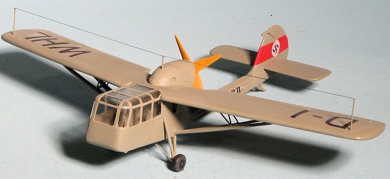
In 1937, a specification was drawn up for an air observation/army co-op aircraft that had superlative Short Take-off/Landing (STOL) capabilities. The three aircraft in consideration was the Fi-156 (already being tested before the specs were released), the Bf-163 and the Siebel Si-201, these latter two flying in 1938. While the Bf-163 was more like the Fi-156, the Si-201 was rather unorthodox with its Argus As10 V-8 air-cooled engine in a pusher configuration. This allowed superlative viewing from the forward cockpit and so  the pilot was seated in the back. The aircraft had high lift devices such as full span automatic leading edge slots and four section Fowler-type flaps with the outermost flaps also acting as ailerons.
The fuselage was of welded steel-tube construction with metal skinning and a plywood-covered wing. The pilot and observer were seated in tandem in the extensively-glazed forward fuselage, the observer being positioned ahead of the pilot with his seat offset to starboard. The first of two prototypes of the Si 201 flew during the early summer of 1938, revealed excellent short take-off and landing characteristics, and was found to possess acceptable slow-flying characteristics closely comparable with those of the Fi-156, however at the upper end of the speed scale tail flutter proved troublesome. Considerable effort was expended in damping out oscillation in the tail boom which developed under certain flight conditions, and the second prototype, which featured some simplification of the high-lift devices, was flown with a somewhat sturdier tail boom. The most serious shortcoming of the Si 201 proved to be the extremely limited cg travel permitted by its configuration, and when Siebel was ordered to abandon further development of the aircraft the problem of tail flutter remained largely unsolved.
| THE KIT |
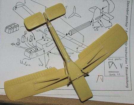
Kora's kit of the 201 is in its usual tan resin. The fuselage is in three sections with the tail boom and fin section separate. A large vacuformed canopy is supplied and the interior has two seats and an instrument panel. My kit was missing the control column and what looks like a radio box for the sidewall. The seats are very narrow and it seems to me that they may be undersize as they will look almost child-like in what is a huge (and undetailed) interior. May want to look into replacements. There is a one piece wing which is beautifully molded and seems flawless. Can't say that for many of the other kit parts. The main fuselage section has some air cavities and crud on the outside of it. I also found some crud and resin bubbles a ttached to the underside of the two props. The landing gear and wing struts are flat on the bottom and will need to be gently sanded to give a proper airfoil shape. The upper wing engine pod has the exhaust mis-drilled as they are not in a straight line as shown in the box art and instructions. This will mean filling them and re-drilling them. Not sure how this managed to sneak past quality assurance. A forward skid is also poorly molded and will need replaced with wire. Wire is needed for several of the smaller supports and Kora provides a 1/1 drawing so you can make these bits.
Instructions consist of a single small sheet with color information and painting guide and another single sheet with a basic exploded diagram. No interior colors are given, but at this time, RLM 02 would be the standard interior shade. The decal sheet provides markings for both aircraft, the v1 prototype having only a tail swastika while the v2 has registration codes. Decals appear to be ALPS printed as it has a continuous carrier over all the markings. There is no indication as to which aircraft uses which prop blade as both a three and four bladed prop are included.
| CONSTRUCTION |
This is one of those kits I have always wanted to build, but for whatever reason, something else seemed to usurp it on the build pile. After nearly 7 years of procrastination, I figured I should get on the stick and so it begins.
First step as with most resin kits, is to remove pieces from their pour stubs. This was accomplished using a fine razor saw. It is probably one of the more time consuming chores. The next was to test fit the bits that needed it and do some additional sanding to remove the rough spots as well as to make sure the parts would fit properly before applying the super glue. I was a bit dismayed to find some air bubbles in the wing struts, as those are rather thin and cannot take a lot of handling. However, fixed they must be and as usual, I used super glue for this, the water thin type.
 The first parts that I glued together were the engine pod to the upper wing. There are holes in the wing that the pod fits into. These needed to be drilled through and the pegs on the underside of the engine pod had to be trimmed down a bit in circumference. Typically, my sawing was erratic as the pour stub went into the underside of the pod so there were gaps that needed to be filled. I also took this time to cement the tail boom to the forward fuselage section. The mating surfaces here are in need of a bit of angled sanding as the tail boom does not go straight back, but is angled up a bit. Nothing that filler cannot fix!
Now to align the wing on the fuselage section, there are holes drilled in the upper fuselage. Unfortunately, there are also holes in the wings. One should have been pins. I used sections of plastic rod to glue into the fuselage section. It is important to find sections that are at or near the proper diameter so there is not a lot of wiggle room. I found that 3/32 Evergreen tubing (2.4mm) was the perfect fit so cut two small sections and super glued them in place.
The next thing to do was to attach the fin. I have to say there is no easy way to do this. The attachment point on the fin piece is bigger around than the fuselage and while things look nice and neat in the instructions, it is anything but. I attached it, used filler at the attachment point and then did my best to bl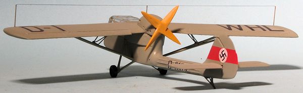 end things in. Not as successfully as I would have liked. While fussing with that, I installed the two engine air scoops. These are not show in the instructions at all, so be careful not to miss them as they will be difficult to install and blend once the wing is attached. I need to apply filler all around the edges as they did not match up well at all. These were attended to and the kit laguished for several months, as happens to quite a few of my builds. It is all due to running into an area in which I've no or little experience, which in this case was properly bending some wire.
After the hiatus, I sanded down the intakes and attached the wing. It was then that I noticed that the engine wasn't quite as centered as I'd have hoped, but I put it down to the need to have it off a bit to prevent 'swing' on take-off. I attached the horizontal tailplane at this time and did the usual filler work at the roots. The paper instrument panel was attached at this time as well.
Then I started bending wire. There is a rather complex arrangement for the wing struts that ended up looking OK, though it would look better had I soldered straight sections together rather than bent them with pliers. I also bent the boarding stairs, the vee strut for the tail skid and cut the lengths for the landing gear.
 Cleaning up the gear legs and the wing struts was not fun, especially the wing struts as they broke during this process. I then glued on the wing struts, the tail gear (after drilling a shallow hole to accept it) and the landing gear. I noticed after I attached the landing gear that the wheel attachment area is not lined up with the line of flight. I guess the mold maker did not keep in mind that the gear legs would not be hanging straight down! Some additional filler and super glue helped to smooth out the attachment areas. The rather convoluted smaller wing struts that I bent out of wire fit rather well and did not look too horrible. Still might have been better to do these out of straight pieces of sprue.
I then trimmed the canopy piece and did a lot of test fitting. I needed a small shim on one side and while that took care of much, there were still areas where it could have fit better. I've never been good with vacuformed canopies and that continues to be the case. This was attached using clear gloss paint. I also filled any gaps with this material. Then I used super glue to ensure it was attached so I could do a bit more gap filling without concerns that the canopy would break free. Using the paint to close gaps prevented any of the canopy from fogging from the super glue. Even then, I still used filler to smooth out the transition between vac and resin as the canopy stuck out a bit from the side and could not be sanded down. With the canopy masked and the broken tail strut repaired, I headed for the paint shop.
| COLORS & MARKINGS |
First step was to paint the fin/rudder white then red for the tail band. This was masked off and the rest of the airframe was painted with Model Master RLM 02 enamel. The prop was painted 'wood' using Vallejo acrylics and the wheels were black with weathered black tires. I used a piece of stretched sprue for the prop shaft and installing a long section into the prop was a big help when it came to painting. Once dry, the 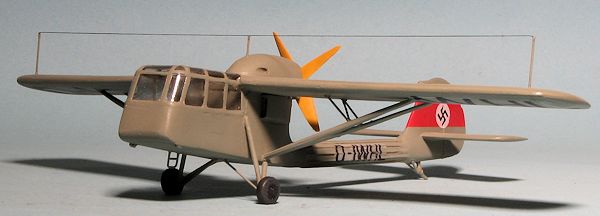 airframe was given a couple of coats of clear gloss acrylic and then it was time for decals.
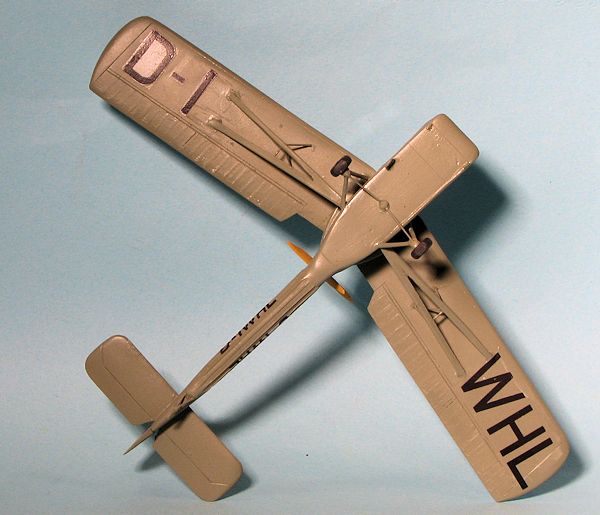
The kit decals are well printed, but I should have suspected issues. I got the tail band swastikas on with not too much trouble, but when I put one of the side codes into water, it broke into bits when I tried to remove it from the backing. I then coated the decal sheet with Microscale decal film which did not work well as it bleached out portions of the markings. No option but to make new ones. I scanned the extant markings and darkened the letters. Then they were printed out and coated. Unfortunately, they only work well on flat surfaces and even then I had issues with silvering. Those on the boom silvered mightily and though I tried a succession of setting solutions, none were effective. Thanks to careful lighting, you cannot easily see this silvering except on the underside shot below. The Solvaset actually dissolved one of the letters. I gave up in disgust and flat coated the airframe before attaching the final bits.
| FINAL CONSTRUCTION |
Really not much here. I first cut lengths of bronze wire for the antenna supports. I had to drill a hole for the one that fit into the engine nacelle. I then attached the wheels and finally the prop. I used EZ Line for the antenna wire.
| CONCLUSIONS |
 This is one of those deceptive kits that looks to be straight-forward in the box, but proved to be anything but. This accounts for the kit being on the shelf of doom for several months before I returned to it. Even then, the built was not on the fast track and I fiddled with it when things were lax with other builds. Eventually, I got it finished and so that is a good thing, but I will have to warn anyone else wanting to attempt this one that it will take more skills than I have to turn it into an award winner! Recommended only for those with lots of experience, including some scratch building abilities.
| REFERENCES |
'The Internet'
August 2013
My thanks tohttp://hobbyshop.cz for the review sample.
Copyright ModelingMadness.com. All rights reserved. No reproduction in any form without express permission from the editor.
If you would like your product reviewed fairly and fairly quickly, please contact the editor or see other details in the