| KIT #: | 11671 |
| PRICE: | $ |
| DECALS: | Two options |
| REVIEWER: | Scott Van Aken |
| NOTES: | 2018 release |
| HISTORY |
The Beechcraft T-34 Mentor is an American propeller-driven, single-engined, military trainer aircraft derived from the Beechcraft Model 35 Bonanza. The earlier versions of the T-34, dating from around the late 1940s to the 1950s, were piston-engined. These were eventually succeeded by the upgraded T-34C Turbo-Mentor, powered by a turboprop engine. The T-34 remains in service more than six decades after it was first designed.
 After extensive testing, the USAF ordered the Mentor into production as the
T-34A in early 1953. The first production T-34A was delivered to Edwards Air
Force Base, California, in October 1953 for evaluation, and deliveries to
the Air Training Command (ATC) began in 1954. The T-34A commenced service as
USAF's initial primary flight trainer at "contract" pilot training air bases
across the southern United States, replacing extant North American AT-6
Texan trainers. Following training in the T-34A, USAF pilot trainees would
advance to the North American T-28A Trojan for intermediate training.
After extensive testing, the USAF ordered the Mentor into production as the
T-34A in early 1953. The first production T-34A was delivered to Edwards Air
Force Base, California, in October 1953 for evaluation, and deliveries to
the Air Training Command (ATC) began in 1954. The T-34A commenced service as
USAF's initial primary flight trainer at "contract" pilot training air bases
across the southern United States, replacing extant North American AT-6
Texan trainers. Following training in the T-34A, USAF pilot trainees would
advance to the North American T-28A Trojan for intermediate training.
The T-34A Mentor remained the standard USAF primary trainer until the introduction of the Cessna T-37 Tweet jet trainer in the late 1950s, replacing both the T-34A and T-28A. This also coincided with ATC's implementation of the Undergraduate Pilot Training (UPT) syllabus at various air force bases in the United States under ATC claimancy and phaseout and closure of the contract pilot training air bases. As they were replaced by T-37s, many T-34As were turned over to USAF aero clubs at air force bases in the United States and USAF air bases overseas. In all, the USAF acquired 450 T-34As.
As the U.S. Air Force replaced the last of their T-34As at the beginning of the
1960s, their role taken over by the propeller-driven T-41 Mescalero and the T-37
Tweet primary jet trainer in UPT, those T-34As not
 allocated to USAF aero clubs
or marked for foreign military sales or transfers were turned over to the USAF
Auxiliary, the Civil Air Patrol, for use as search aircraft. However, the
T-34A's low wing limited its utility in an aerial search and rescue role, and
maintenance issues, particularly expensive wing spar repairs that became
apparent in the late 1990s, resulted in the last of the former USAF T-34As being
withdrawn from CAP service by 2003.
allocated to USAF aero clubs
or marked for foreign military sales or transfers were turned over to the USAF
Auxiliary, the Civil Air Patrol, for use as search aircraft. However, the
T-34A's low wing limited its utility in an aerial search and rescue role, and
maintenance issues, particularly expensive wing spar repairs that became
apparent in the late 1990s, resulted in the last of the former USAF T-34As being
withdrawn from CAP service by 2003.
The U.S. Navy kept the T-34B operational as a Naval Air Training Command initial primary trainer at the former Naval Air Station Saufley Field, Florida until the mid-1970s and as a Navy Recruiting Command aircraft until the early 1990s when the last examples were retired as an economy move. Others continue to remain under U.S. Navy control as part of flying clubs at naval air stations and marine corps air stations.
| THE KIT |
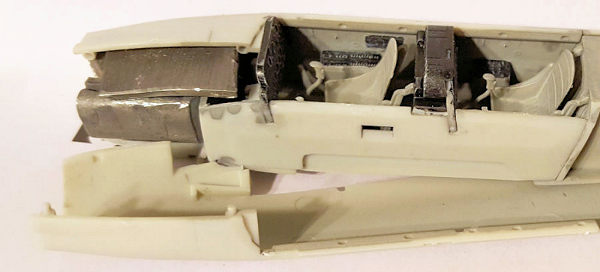
It is nice to see this one done in a larger scale. The cockpit consists of a floor with molded on side consoles onto which a right and left side are attached. These sides include parts of the nose gear well which, when added to the bit in the floor piece, will make up the three piece well. A rear section completes the tub. The instrument panels are devoid of dial detail and no decals are included. Each of the two seats is five parts with the cushions containing belt detail. These, the control sticks and trim wheels are added to the cockpit before the interior is trapped between the two fuselage halves.
One then has to find room for the 28 grams of weight
and frankly, it will be a challenge. In the front a two part forward cowling
allows you to trap the prop shaft in place. After gluing in the small rudder
fillet, the wing spar can then be added. Landing lights are then added to the
lower wing before it, and the upper
 halves are joined to the fuselage.
Next the tailplanes are joined together and installed along with the long exhaust pipes. There are four pieces to the canopy/windscreen combo. These appear to be too thick to have the canopies posed open. Perhaps a single piece would have been better.
The build then moves to the landing gear. Frankly, the gear appears to be quite scale, which means I have my doubts if the nose gear will be able to hold up the 28 grams of weight. I'm sure SAC will provide metal replacements. The kit can be built gear up if one wishes and a display stand is provided for that option. No specific location for the stand mounting hole is molded in so you basically pick a spot and drill. To do gear up, the door mounting tabs will need to be removed. A four piece prop that consists of two separate blades and a forward and aft spinner are provided. You are given a choice between a blunt and more pointed spinner. Check your references.
Instructions are very well done and could probably have been reduced from the 23 construction steps as some only show one or two pieces being attached. Still, they are nice to have. There are two rather insipid markings options. One is the box art plane which is a YT-34A. The other is a generic JASDF plane, also in unpainted metal. You will need to paint the anti-glare panels and wing walk areas. Fortunately Caracal Models has two very nice aftermarket sheets that will provide something more interesting.
| CONSTRUCTION |
 Step one for me was to identify what colors I needed
to paint things prior to construction. The instructions stated that the
interiors could be either interior green or a dark grey. I chose the dark grey
and used FS 36231 dark gull grey as it is and was a popular interior color. This
included the bits for the seats as well as the instrument panels. The instrument
panel faces were painted flat black along with some of the interior details. The
seat cushions were painted khaki with buff belts. I also prepainted the landing
gear parts with aluminum along with the inner gear doors.
Step one for me was to identify what colors I needed
to paint things prior to construction. The instructions stated that the
interiors could be either interior green or a dark grey. I chose the dark grey
and used FS 36231 dark gull grey as it is and was a popular interior color. This
included the bits for the seats as well as the instrument panels. The instrument
panel faces were painted flat black along with some of the interior details. The
seat cushions were painted khaki with buff belts. I also prepainted the landing
gear parts with aluminum along with the inner gear doors.
First parts actually assembled were the wheels and the tailplanes. Easy stuff. Then I assembled the seats. I accidentally cut one of the upper mounting pieces thinking it was part of the sprue. Be careful. Then the sidewalls were glued to the floor. This was initially not an easy task as the instructions are not helpful, but once you figure out how they are attached, it is a fairly straight-forward task.
Once dry, the seats were installed. This was not a
simple task as getting the mounting pins in the holes, especially for the back
seat, took some concerted effort. I'd almost suggest installing the back seat
prior to attaching the sidewall pieces. Front seat wasn't that tough, but has to
wait until the rear instrument panel and coaming are glued in. For some reason,
the instructions want you to attach the trim wheels after the
 seats and
instrument panels are installed. Do it earlier. You'll be pleased you did as it
is a bit of a pain to get them in with all that other stuff in there. Front
instrument panel was attached, followed by the control sticks. It was all set
aside to dry.
seats and
instrument panels are installed. Do it earlier. You'll be pleased you did as it
is a bit of a pain to get them in with all that other stuff in there. Front
instrument panel was attached, followed by the control sticks. It was all set
aside to dry.
The nearly completed cockpit was then glued into the
right fuselage half. Fit is very good. Then it was time to figure out how to
stuff one ounce (28 grams) of weight in the front. I weighed out an ounce of lead
sheet and then started rolling and trimming to get it into the nose section. No
way I was going to get it all in. I was able to ins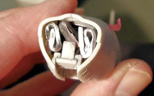 tall about 22 grams and by
attaching the other fuselage half, lower wing and the tailplanes with tape,
figured it was enough. I then closed the other fuselage half.
tall about 22 grams and by
attaching the other fuselage half, lower wing and the tailplanes with tape,
figured it was enough. I then closed the other fuselage half.
After the usual seam work, I glued on the previously assembled tailplanes. There is a wedge of plastic that fits under the rudder that is a bit tricky to install. You have to push on it until is snaps into place. Fit of the wings wasn't the greatest, but it wasn't horrible. Biggest issue I had was the rear portion as it did not seem to want to fit flush. A bit of grinder work should cure that and I'll do such the next time I build one of these. I then installed the forward cowling pieces.
It was then time to attach the rest of the interior bits and the canopy. I found that the front instrument panel is too far forward. It needs to be a bit farther back for the forward coaming to fit properly. If this coaming is too far forward, then the windscreen will be too far forward and there will be some large gaps. I did some prying on the already glued in place instrument panel to move it farther back. Fit of the rest of the clear bits is quite good.
Clear bits were masked and the gear wells filled with Silly Putty. Then it was time for paint.
| COLORS & MARKINGS |
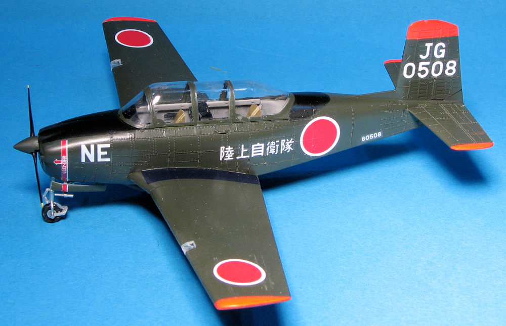
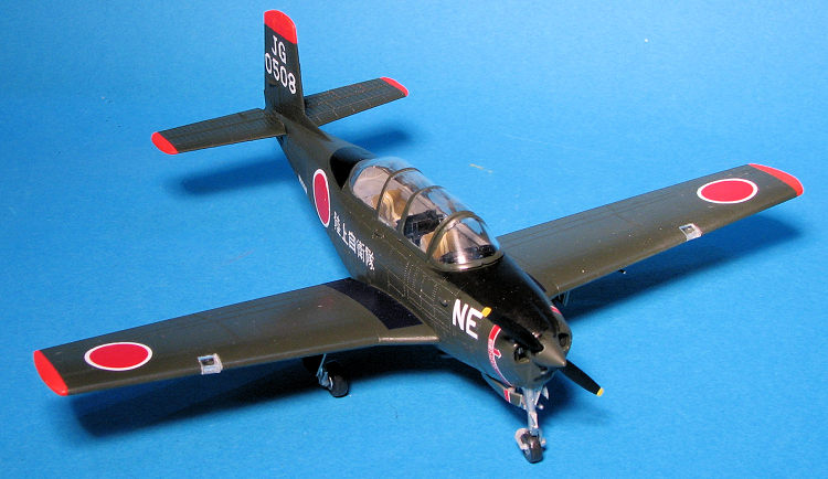
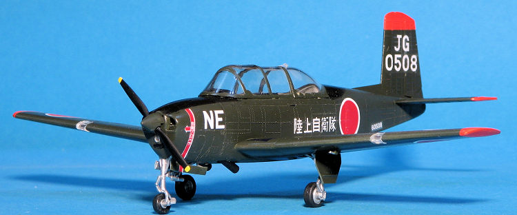
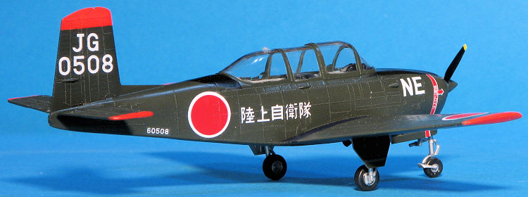
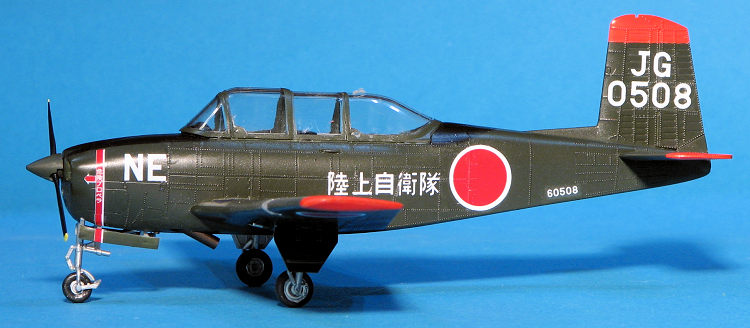
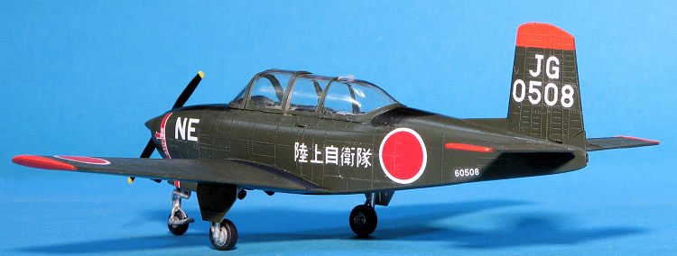
I am using Caracal's 48-086 for International Mentors.
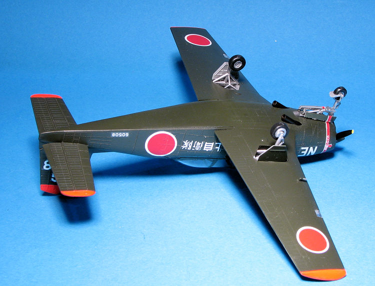
I chose the JGSDF version that is in dark OD with dayglo tips. I first sprayed
everything with TS-70 which is Tamiya's JGSDF olive drab. Then the areas around
the tips were masked and the tips sprayed with Tamiya matte white. This was
followed by Testors Model Master florescent red/orange. The instructions would
have you use international orange, but these were daglo. The anti-glare panels
were then masked around and painted black. I chose to use stripe decals
 for the
wing walk areas. I didn't have black ones of the proper width so used a very
dark blue and under most light it looks OK.
for the
wing walk areas. I didn't have black ones of the proper width so used a very
dark blue and under most light it looks OK.
Before applying decals, I put the airframe on its gear. Both the nose and the main gear are sturdy once in place. However, they are quite fiddly to get there. I found this particularly true of the support framework for the main gear as you have to twist it around in the well to get it into its attachment points.
The decals themselves are nicely done but be advised that the sheet runs out of glue very quickly. If you cut out two markings, odds are that the second one will be stuck to the backing before you can use it. I found that the prop warning decals were not only too long (better than too short) but were also off register. Note that the small serial numbers on the lower rear fuselage are supposed to follow the bottom fuselage line so are not put on crooked.
With the majority of the decals in place, I started adding things like wheels and gear doors. The main gear doors need to have the attachment hinges cut to fit. You can install them at the same time as the main gear if you wish, but trimming them for later installation is easier. The nose gear doors were a real challenge to get in place and I had to attach them several times before they finally stayed there.
 It then moved on to things like the prop, landing
light covers and antennas. The kit offers two different blade shapes, the option
to do a two or three blade prop, and two different spinner lengths for each
option. This one takes the squared off two bladed prop with the longer spinner.
Naturally, I lost the backing plate so had to make something that would work.
The exhaust were installed along with the pitot, followed by the prop. Then a
clear coat was sprayed on and the masking removed. Last step was to install
the landing light lenses, which are a bit too large for the opening.
It then moved on to things like the prop, landing
light covers and antennas. The kit offers two different blade shapes, the option
to do a two or three blade prop, and two different spinner lengths for each
option. This one takes the squared off two bladed prop with the longer spinner.
Naturally, I lost the backing plate so had to make something that would work.
The exhaust were installed along with the pitot, followed by the prop. Then a
clear coat was sprayed on and the masking removed. Last step was to install
the landing light lenses, which are a bit too large for the opening.
| CONCLUSIONS |
This was a nice build. It does have its idiosyncrasies so requires some careful construction. One thing I did notice when comparing the model to photos of the real deal is that the kit landing gear are molded in the fully extended position. Lowering them is possible, but will not be an easy task. I also noted that the nose gear should be a bit more of a forward angle. This will make the retraction strut too short. This is not a Tamiya kit, but is one that any modeler with some experiences can make into a nice model.
| REFERENCES |
https://en.wikipedia.org/wiki/Beechcraft_T-34_Mentor
17 April 2020
Copyright ModelingMadness.com. All rights reserved.
If you would like your product reviewed fairly and fairly quickly, please
contact the editor
or see other details in the
Note to
Contributors.
Back to the Main Page
Back to the Review
Index Page
Back to the Previews Index Page