Trumpeter 1/32 F4U-4 Corsair
| KIT # | 2222 |
| PRICE: | $69.95 MSRP |
| DECALS: | two options |
| REVIEWER: | Scott Van Aken |
| NOTES: | It is a big-un |
| HISTORY |
The F4U-4 was one of the more important variants of the Corsair. Seven prototypes were built, anticipating the many problems which would arise from the proposed changes. Five F4U-1s were pulled from the production line to be modified into the XF4U-4A, ‘4B, ‘4C, ‘4D and’4E. Two more "FG-1" aircraft (identical to the Vought F4U-1) were pulled from Goodyear’s production line. They were all fitted with the Pratt-Whitney R-2800-18W engine which produced 2,100 hp (1,567 kW) and 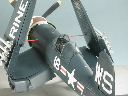 sported a new four blade prop. The engine also had methanol-water injection which boosted the war emergency power rating to 2,450 hp (1,828 kW) for about five minutes. The 18W engine necessitated changes in the basic airframe to handle the extra power and the turbo air intake was mounted on the inside bottom of the engine cowling (it was called a "chin scoop") while air for the intercooler and oil cooler continued to be drawn from the wing slots. The F4U-4 was clocked at a top speed of 446 mph (717.75 kph) at 26,200 ft (7,985.76 m).
Although it wasn’t designated by the Navy as such, the dash four was a fighter-bomber for all intents and purposes. It had 6 Colt-Browning .50 cal. (12.7 mm) wing mounted machine guns (the F4U-4C substituted four 20 mm cannon), plus it could carry two 1,000 lb (453.6 kg) bombs or eight 5 inch (127 mm) rockets. The first 300 of the production F4U-4Cs were assigned to Marine Air Group 31 and were taken into the Battle for Okinawa aboard the escort carriers Sitko Bay and Bereton. The Army and Marine riflemen who fought that battle on the ground remember the F4U-4 as the "Sweetheart of Okinawa" and it undoubtedly saved many hundreds of their lives. The -4 was also used in rather large numbers post-war and saw extensive use during the Korean war as the mount of choice of Marine fighter-bomber units. Its ability to haul heavy loads and absorb battle damage were instrumental in helping to turn the tide of the war in the early days, when things looked rather bleak. Eventually, they were replaced by F9F Panther jets as even the Marines had to modernize!
| THE KIT |
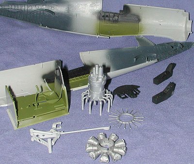
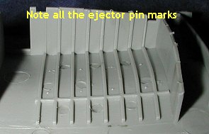 Trumpeter continues to be a bit of an enigma when it comes to the design of their kits. This one is no exception and has several rather odd features. It comes in a huge box that protects the kit very well. Each of the individual sprues is separately bagged and some of the more delicate parts are individually wrapped to prevent damage. This kit continues the use of 'rubber' tires and metal bits for movable control surfaces. Detailing is generally excellent, however, there continues to be a problem with ejector pin marks. If you look at the image of the wheel well, you can see what I mean. In several cases, simply turning a part over would have resulted in a part where the ejector marks would not be seen in the final build. However, the engineers have chosen to do the mold in such a manner that some parts are full of these marks and removal nearly impossible.
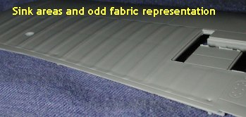 Another concern is the representation of fabric on the wings and tail control surfaces. It is a bit odd-looking from my perspective and looks more like corrugations than anything else. The ailerons and flaps are very smooth as if they are metal covered, which may be the norm for a -4. There are also some sink areas. Not all are that bad and I've chosen what I think is the worst of them to show you on the trailing edge of the upper outer wing. Filling this sink area will result in the loss of a lot of the 'fabric' detail. The other large sink area is on the upper side of the inner wings where the wheel well detail is visible from the outside.
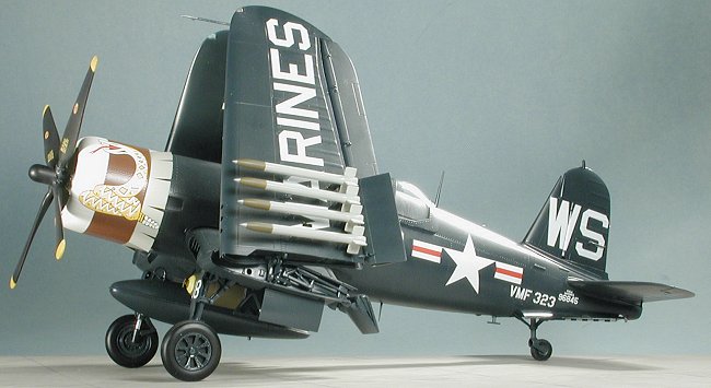
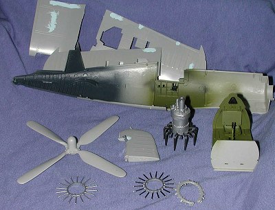
OK, other than these things, what sort of options do you get? Well, the kit allows you to build the wings folded or extended. There is no sub-spar for the extended wing position. You also get full gun bays for both wings. Ordnance consists of eight 5 inch rockets and a pair of 500 lb bombs. One can put drop tanks on the bomb racks if one so desires. The holes are 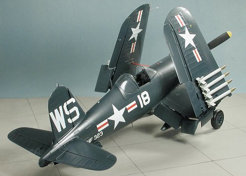 already drilled for these items so those who want a clean plane will have to fill them. The windscreen and canopy are separate, so one can display the canopy in the open position. Another oddity is that the tail wheel is designed to be retracted, but not the main gear. The gear doors are also fixed. Why this option was chosen is beyond me and I'll be gluing mine in position.
The cockpit is quite well detailed, though there is no seat harness. Fortunately, aftermarket can take care of this missing detail. I'm hoping the -4 had a full floor as that is what is provided in the kit. I should also mention at this time, that all of the cockpit, wheel wells and other internal structure is listed as being US Interior Green. Not sure if this is really correct or not and I'm suspecting that it should be yellow zinc chromate primer for the gun bays and engine bay, dark blue for the wheel wells and black for the cockpit.
As with the earlier 1/24 Bf-109G-6, the flight controls are all designed to be movable. While this is nice, there are a few concerns. One is that I believe the -4 Corsair's control column was spring loaded so the ailerons, elevators and rudder would normally be in the neutral position. Secondly, there are various actuator rods that attach from the flight surfaces to the control surfaces and these would prevent the builder from positioning the control surfaces in anything other than the neutral position. Finally, after my experience with the control surfaces breaking away from their mounts on the 109, I'll be cementing mine solid!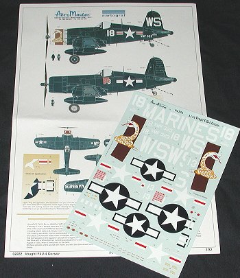
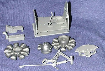
Undoubtedly, the prime goodie for this kit is the engine. It consists of a zillion little parts and will consume a lot of time, but should look just great. As with the 109, the engine cowling is provided as a clear piece to allow the builder to show off his work. However, it seems as if it would be easy enough just to fit on the cowl so it can be taken off. Fortunately, Trumpeter has not included any of that miserable rubber wiring so I'm very pleased about that aspect of things. The cowl flaps for the engine have been designed to be in the open position only.
Instructions are in a booklet form and are very good in terms of providing clear and unambiguous assembly procedures. Color information is given where it is needed, though I'm a bit suspicious of some of the choices. Decals are by Aeromaster and superbly printed by Cartograf in Italy. Two aircraft are provided, both in overall sea blue. First is a Korean War aircraft from VMA-323 'Death Rattlers'. This aircraft has a large rattlesnake on a white cowling and will undoubtedly be chosen by most modelers. The other is a WWII -4 Corsair as flown by Ken Walsh for his final WWII victory in June of 1945. As Corsairs go, it is pretty boring with little more than the covered up aircraft number and his kill board to add interest.
It looks very much like it will be a most interesting build. I'll be doing the day by day construction as I did on the 1/24 Bf-109G-6 so stay with me for a most interesting experience!
| CONSTRUCTION |
30 November 2003
After reading the instructions with much care, I started on doing subassemblies. Now I'm going to be jumping around the model for a while in doing this, but it is the way that I generally build things.
I began with the engine and glued together the crankcase assembly and both rows of cylinders. I'm not sure just how one is supposed to get rid of the seams that are on the cylinders, but it appears that at least the upper ones will be covered by the rocker arm covers. These were then painted Dark Aluminum using Alclad II over the bare plastic.
 My attention then turned to the interior. I glued the rudder pedals to the back of the instrument panel and then assembled all of the interior bits (well most of them) to the floor assembly. The seat pan has two very nasty ejector pin marks in it that will be a real pain to try to remove. I've decided to try to fill them with white glue and see how that turns out. It will probably take several applications. I also noted a large number of ejector pin marks on the detail side of the forward bulkhead. Removing them also seems to be impossible so I left them alone. As a side note, I suggest gluing in the seat before the seat parts are fully dry so that you can be sure they will fit properly. At this time, I also glued together the two side consoles.
The other bit I worked on was the tail gear and tail hook assembly. As noted in the kit description, I'm going to glue this in the lowered position, but I still need the various pistons to 'work' to get them in the proper position. It is a bit fiddly and will take some careful cleanup to get everything to fit well. I've most of the bits together in the image you see. I left the actual tail wheel strut halves unglued so that I could more easily spread them apart to install the tail wheel at a later date.
1 December
 Had a lot of non-modeling things to do today (like burning leaves) so little was accomplished. I did manage to do some painting of various bits (like the interior and fuselage insides. I assembled the four parts for the tail hook brace assy and glued that in the rear fuselage. I also assembled the aft accessory compartment for the engine. The intake tubing has a lot of mold seams that you'll have to remove if you want this to be a contest quality model. I came to the realization that with the cowling on, not much will be seen so only did the usual clean-up. For a contest, you'll have to use filler on each of the joins of the intake pipes; too much work for me.
I also removed and painted one of the pushrod assemblies as well as installed the final little piston assy to the tail wheel assembly. Before painting the cockpit area, I installed the side wall framing, the throttle quadrant, and canopy crank. There were ejector pin markings all over the place in the interior and even on the framing there were holes that would need filled. I've come to the conclusion that Trumpeter really needs to get its act together regarding all these ejector pin holes and marks. To get this thing ready for any kind of contest, the builder will have to spend an inordinate amount of time filling these damn things. For those wanting a nice shelf model, they can be ignored.
The final thing I did was to start putting in the little 'U' shaped pipes in the cylinder heads. I'm not sure I got the colors right for the cockpit. The more I think about it, the more I'm leaning towards painting all of the bulkheads with the interior green. I'm convinced that all the wheel wells will need to be sea blue.
2 December
 After some additional conversations and a nice photo of an unrestored F4U-4 cockpit, I've had to do some repainting; in this case, painting the entire interior with interior green. I also did some painting of the accessory section and one set of push rods. I painted the intake tubing gunmetal and the push rods were done in black. Not very exciting, but it is somewhat time consuming. I also had the 'pleasure' of shaking a bottle of paint when the cap wasn't fully tight. I do this every year or so and it is always a 'dammit' moment!
On other fronts, I glued the prop together after doing the usual clean-up. It is a really big unit and it also seems that the blades are a tad on the thick side. The rudder was also glued together. This has a single hinge with a very small metal rod (pre cut, thankfully) that gets sandwiched between the rudder halves.
I also took this time to start filling some of the more egregious sink areas on the wings. I know I'll not be able to fill them all as it would mean wiping out all the detail, but at least I can get the worst of them. There was a small sink area on the rudder than needed filled as well. I also painted a few more engine bits with aluminum. The other deal of the day was to paint the back of the instrument film with white, and when that was dry, it was attacked to the back of the instrument panel face with clear paint . This instrument panel face is molded in clear plastic for some odd reason. That still didn't prevent the face from having ejector pin marks on it, though.
3 December
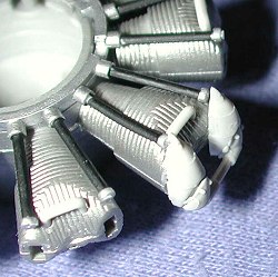
There are always those days when one has more things to do than there is time. Today was one of those days so little was actually accomplished. I did continue some on the most time consuming part of this kit; the engine. I installed the 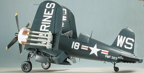 small crossover tubes on the second bank of cylinders and started in on the rocker arm housings. These are each three small pieces; two atop each cylinder and a cross-over piece. However, these three bits must be glued together before being glued on the cylinder. I tested one cylinder by gluing the two rocker arm covers first, and it just didn't work. Here is the situation. Each of these small constructs is basically flat. The top of the cylinder head is slightly curved (see the image below). Even when the bits are glued first, there is a problem getting them to fit properly atop the cylinder. I've completed but a few as each needs to be clamped into position for the glue to dry. I have also test fit each one by temporarily installing the pushrod assembly (that spider looking thing in yesterday's image) when installing the rocker arms. That is because I want to paint the cylinder head at one time rather than prepainting all those small rocker arm bits.
The only other thing I did was to paint the prop, install the instrument cluster in the panel and drybrush some of the detail bits in the interior. I should mention that the face of the instrument panel really needs to have more relief as it is quite flat with minimal detail. You may also want to sand the thickness of the clear part quite a bit as the instrument dials are set back pretty far; like it was with the 109.
4 December
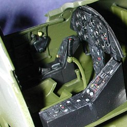 Not much happening today as busy finishing up tomorrow's review kit, which does take precedence over long term builds like this. I did manage to pretty much finish up the cockpit and after some additional painting, installed it in a cockpit half. Fit is quite good and it certainly looks nice in there. Fortunately, much of the wiring is not readily visible, thanks to the consoles so it doesn't look as bare as the 109 did. You can see one of the many dreaded ejector pin marks on the interior to the left of the instrument panel as well as one of the marks on the panel face (right side). The rest of the time I spent gluing on more of the rocker arm subassemblies. I made sure that I had the pushrod piece in place to get the proper fit and clearance. You can see from the image that I'm on the second row of cylinders. It is a rather time consuming portion of the build. I would not have been unhappy if Trumpeter had made these bits a single mold instead of three parts!
5-7 December
This weekend was spent doing much of my work on the engine. It was pointed out to me that I'd placed the rocker arm assemblies on the wrong part of the engine. They are supposed to go between each of the cylinders. Taking several more looks at the drawing provided in the instructions, I saw that it was the case. I can only say that I was confused by the very detailed drawing that shows the completed engine with the parts being added. This meant a lot of prying to get the parts off and replaced. During this evolution, I managed to break a lot of them and lost one set somewhere. It went 'zing' and I never even heard it hit anywhere so after a lengthy search, I gave up looking and placed the missing section in the bottom and the back.
Next was to paint the completed cylinder assemblies with aluminum. I then brush painted each of the connecting tubing black to add some interest. The next step was to glue the cylinder assemblies and other various engine bits together. One has to be very careful when installing the bits to be sure they are not misaligned as it is quite easy to do. Many comparisons with the drawings are needed to be sure all is OK. Then I added the accessory section to the back. This includes the induction lines that go into the cylinders. The fit of this part is good on the back cylinders, but getting everything to properly 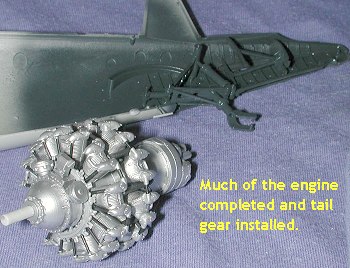 attach in the cylinders is another thing all together. There is a lot of flash around the ends of these parts that must be removed and even then it seemed as if the tubing was too short. I clamped all these parts down to get as good a fit as I could, but it still wasn't good enough.
While all this was drying, I started cleaning up the exhaust. These parts have a lot of those little 'pips' on them from molding and it also seemed as if the mold had shifted a bit as I had to spend several hours scraping and filing to get them cleaned up. They also seem a bit too small in diameter as well. The ends of the pipes are molded solid so they will need to be drilled out to present a realistic appearance. While still on the sprue, but after most of the cleanup was done, they were painted Burnt Iron using Testors Metalizer. I also painted the tail gear strut assembly sea blue in preparation for installation in the fuselage. When dry, it was glued in the down position. Tomorrow I'll add the exhaust and close the fuselage halves.
Copyright ModelingMadness.com. All rights reserved. No reproduction in part or in whole without express permission.
If you would like your product reviewed fairly and fairly quickly, please contact the editor or see other details in the Note to Contributors.