
Accurate Miniatures 1/48 B-25G Mitchell
|
KIT # |
3432 |
|
PRICE: |
$47.99 MSRP |
|
DECALS: |
Two aircraft |
|
REVIEWER: |
Scott Van Aken |
|
NOTES: |
Pre-release kit |
|
HISTORY |
In the B-25G, a standard 75-mm Army M4 cannon was mounted to fire forward through the nose. This gun was a revision of the famous French 75 of World War I. The basic concept had been found to be feasible via a series of experiments on a converted Douglas B-18A Bolo. However, since the effects of the heavy muzzle blast on the nose structure of the Mitchell were unknown, a complete forward fuselage section was built and trucked to a secret area in California where firing tests could be conducted out of the way of prying eyes. Guided by these tests, the structure was progressively strengthened until full resistance to prolonged firing of 75-mm rounds could be demonstrated.
 B-25C-1 serial number 41-13296 was modified as the XB-25G prototype.
It was fitted with a 75-mm M4 cannon which was 9 feet 6 inches long. The
bombardier-equipped transparent nose was replaced with a shortened
armored solid nose that reduced overall length to 51 feet. The cannon was
mounted in a cradle in the lower left-hand side of the nose. The cradle
extended underneath the pilot's seat and a spring mechanism formed part
of the gun mounting to take up the 21-inch recoil.
B-25C-1 serial number 41-13296 was modified as the XB-25G prototype.
It was fitted with a 75-mm M4 cannon which was 9 feet 6 inches long. The
bombardier-equipped transparent nose was replaced with a shortened
armored solid nose that reduced overall length to 51 feet. The cannon was
mounted in a cradle in the lower left-hand side of the nose. The cradle
extended underneath the pilot's seat and a spring mechanism formed part
of the gun mounting to take up the 21-inch recoil.
The modified aircraft made its initial flight on October 2, 1942, test pilot Ed Virgin being at the controls and with test engineer Paul Brewer being on board. Because of the additional weight and drag, maximum speed fell to 278 mph. However, flight tests found the stall characteristics to be normal and diving at speeds of up to 340 mph revealed no problems.
Five more B-25Cs were converted to B-25G standards, and 400 examples of the B-25G were built new at Inglewood in -1, -5, and -10 production blocks. 58 B-25C-20 and -25 bombers were modified with solid nose, two nose guns and 75-mm cannon and were redesignated B-25G.
Up to the end of the Second World War, the 75-mm cannon of the B-25G was the second largest gun fitted to any aircraft, exceeded in size only by the 105-mm cannon fitted experimentally to the Piaggio P.108A. However, the firepower of the B-25G's 75-mm cannon has been exceeded in postwar years by the 105-mm howitzer carried by the Lockheed AC-130 Spectre gunship
 The 75-mm cannon was augmented by two 0.50-inch Browning machine guns
mounted side-by-side in the nose. These guns were to be aimed and fired
by the pilot at the same time as the cannon. The machine guns were
intended to be used as anti-flak weapons and for ranging purposes in the
sighting of the 75-mm cannon. Both the cannon and the nose guns were
aimed by a type N-3B optical gunsight with a type A-1 combination
gun/bomb sight head mounted on the pilot's side of the cockpit. This unit
was also used for minimum altitude bombing.
The 75-mm cannon was augmented by two 0.50-inch Browning machine guns
mounted side-by-side in the nose. These guns were to be aimed and fired
by the pilot at the same time as the cannon. The machine guns were
intended to be used as anti-flak weapons and for ranging purposes in the
sighting of the 75-mm cannon. Both the cannon and the nose guns were
aimed by a type N-3B optical gunsight with a type A-1 combination
gun/bomb sight head mounted on the pilot's side of the cockpit. This unit
was also used for minimum altitude bombing.
Rather than incur the extra weight, high cost, and protracted development schedule of an autoloader, the 75-mm rounds were manually loaded into the cannon by the navigator/cannoneer. Each shell weighed 15 pounds, and 21 rounds of 75-mm ammunition could be carried on a rack next to the breech of the cannon. On production aircraft, this rack was protected by armor plate on three sides.
Aft of the nose, the B-25G had the same armament as the B-25C. The upper dorsal turret was retained, but the retractable ventral turret was often deleted since hydraulic fluid and dust tended to obscure its sighting system. The lower turret was deleted on the B-25G production line effective with serial number 42-65001. The standard bomb bay was retained, but was modified to permit the installation of a standard aircraft torpedo.
|
THE KIT |
Interestingly, I've only built one other Accurate Miniatures B-25 kit and that
was the B-25G. Only in that case, it was done using the B-25B model and the G
conversion set. What was sadly missing from that set was a decent set of
instructions as I found all sorts of missed items from it, causing no end of
building problems. Now the B-25 kit isn't exactly a toss together kit and it
isn't a real easy build. In fact, the buzz phrase on this kit is 'follow the
instructions'. Straying from them will only lead to disaster or at the least a
pack of
trouble.
I'm going to wimp out and refer you to another preview for
a look at what is in the box. This kit is in all
respects exactly the same plastic as the others so nothing has changed. In fact,
I was almost going to refer you to the older B-25G review
for most of the article, but that wouldn't be fair to this particular build.
I've always felt that no two builds are the same and I'm sure this will hold
true for this one as well. What I have done is to lay out all the pieces
of the kit (see above) so you can see that this puppy will fill the box.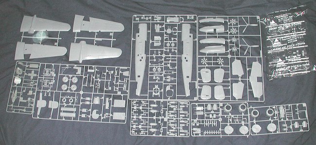
 This kit not only has all the bits in one place (which means a savings of $20
over the conversion-plus kit of old), but also has instructions that are
designed for the kit from the very first. A big help to those of us who stumbled
through the conversion. Of course, the old AM put up a build assistance on their
web site, but it wasn't up until after I'd built that kit!
This kit not only has all the bits in one place (which means a savings of $20
over the conversion-plus kit of old), but also has instructions that are
designed for the kit from the very first. A big help to those of us who stumbled
through the conversion. Of course, the old AM put up a build assistance on their
web site, but it wasn't up until after I'd built that kit!
|
CONSTRUCTION |
I started by assembling the various interior parts. This
included the two guns, the cockpit and the bomb bay assembly. The cockpit
assembly includes the gun and its housing. On my test shot, the housing was
short shot, though not enough to be a major problem. What was a problem was
bending the gun mount. I had trouble with this in the earlier kit and it was the
same for this one. I know that this deal of bending plastic to make parts is
less expensive than having to mold four or five separate pieces, but for me, it
just doesn't work well for this piece. I eventually got it 'sorta' OK, though by
no means perfect and glued it into the housing under the cockpit section. The
rest of the cockpit pieces went together well with no trauma. You are given
decal seat belts and they look just fine once installed. The
cockpit section is painted Interior Green while the rest of the aircraft
interior parts are in Yellow Zinc Chromate. The bomb bay is aluminum as is the
area where the gun is mounted. I didn't paint the bomb bay as this one will have
the doors closed. It will be interesting to see how well the doors fit. Once all
the various bits were painted the overall color, I went into the interior to
paint various bits and pieces black or red or whatever using my paint brush. The
sad truth of this and other Next were the turrets. Now I must
confess to you that these did not go too smoothly on the earlier kit. They went
a bit better on this one. Pay particular attention to the assembly of them both
as they are not intuitive and quite easy to mess up. Despite all my efforts, the
upper turret still didn't fit as well as I'd have wished. Not that it went
together poorly, but it just doesn't seem 'happy' when installed. Anyway, once
all the various interior bits and pieces had been painted and assembled, the
fuselage halves were glued together. On the previous kit, I had the bomb bays
open and the access doors closed and the lower turret blanked off. This one was
just the opposite. The bomb bay doors are not designed to be built in the closed
position so their fit is less than sterling. They were also quite fussy to get
into position. I also had the usual fit concerns with the fuselage halves so
filler was needed on most of it. Meanwhile, I glued together the
wings and horizontal stabilizers and fin/rudders. No problems there at all,
though you should clamp the wings around the landing lights if you want the
parts to properly join or there will be a small gap. Then I glued the nacelles
together and to the wings. These fit fairly well, but there are some areas that
need filler, especially on the upper aft wing/nacelle join. At this time the
exhaust blanking plate and upper carb intake were glued in place. Make sure you
get the right ones as they are designed to match the cowlings. Fit for these
parts is a bit on the loose side so there will be gaps. Decide if you want to
deal with them or not. I didn't. Then the engine cowl flap piece was glued on.
You'll need to sand and fill where it mates with the carb intake.
 bomber kits is that most of the interior detail work
you do will not be seen. If you are in a bit of hurry to get your kit finished
and don't want the added weight of the few plastic parts that go on the
bulkheads, you can leave them off. Anyway, these were drybrushed to bring out
detail (that won't be seen).
bomber kits is that most of the interior detail work
you do will not be seen. If you are in a bit of hurry to get your kit finished
and don't want the added weight of the few plastic parts that go on the
bulkheads, you can leave them off. Anyway, these were drybrushed to bring out
detail (that won't be seen). While discussing engines, these were glued together and painted aluminum. They
were then given a black wash to bring out detail. The cowlings were then
assembled. Actually, this means gluing on the 7 rear row ejector exhaust stubs.
A bit time consuming and make sure you don't lose any as there are no extras!
I should mention that several have said that the cowlings are not the right
shape on the front. Something about the curve being wrong resulting in a
'too closed' look. Well, you can plunk $$ (or
While discussing engines, these were glued together and painted aluminum. They
were then given a black wash to bring out detail. The cowlings were then
assembled. Actually, this means gluing on the 7 rear row ejector exhaust stubs.
A bit time consuming and make sure you don't lose any as there are no extras!
I should mention that several have said that the cowlings are not the right
shape on the front. Something about the curve being wrong resulting in a
'too closed' look. Well, you can plunk $$ (or
Back at the fuselage, it was time to install the gun nose. First I had to
scrounge weights. Fortunately, those that fit into the nose wheel well were
available as I'd not used those on my last kit. This one came with no weights as
it was a pre-production version. I filled the well and then stuck some
additional weight behind the instrument panel. You'll see the well weights from
the outside, but there is no other place to put them. Fortunately for me, this
was a much better fit than the earlier kit. I even was able to get the opening
gun hood to work, but it was a loose fit so I ended up gluing it in place. I
still needed a touch of filler, but nothing like the slathering given earlier.
At this time, I masked all of the fuselage transparencies as doing so later
would be difficult. Next step was the wing installation. No
problems here, though there is a touch of a gap on the underside. Your choice as
to fill it or not as it will be difficult to do without removing detail. At the
back, the horizontal stabilizer was glued in place and then the flat upper
fuselage part was cemented in place. No tail gun position on this one as on the
last. Some care needs to be taken with these parts to ensure a proper fit. I
needed a touch of filler on mine as I wasn't as careful as I should have been.
The fin/rudder parts were then glued on with no trouble. I then masked the
canopy and glued it in place. There are several to choose from so make sure you
use the correct one. Then all the holes (gear, access ladders and such) were
filled with tissue and it was time to apply some paint. CAMOUFLAGE & MARKINGS
One thing I noticed while researching the camo for this model is that the
scheme was not put on in a uniform manner. I've seen photos of everything
from a very neatly done pattern with minimal overspray to ones that were
quite broad and had a lot of overspray, so there is really no need to get
too anal about how tightly done the pattern is. It did take a bit of back
and forth to get things the way I wanted it. When done and dry, the areas
for decals were sprayed with clear gloss acrylic.
There is yet no option for this kit other than the kit decals. These are
very thin and go on well, though you do have to be especially careful not
to tear them. I found that the shark mouth didn't want to snuggle down even
with Microsol, so I ended up having to use Solvaset for this process. Once
the decals had dried, I sprayed a clear matte over them to seal them in
place.
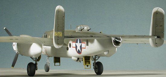
 This particular plane is the test aircraft from Eglin Field in Florida. It is in
the sea-search scheme of OD upper surfaces and white undersides. The
instructions state that the undersides are neutral grey. They are not so don't
paint it that color. The only neutral grey used on this kit is for the disc that
fits on the nose wheel! I used Floquil Reefer White lacquer to do this task. It
not only covers well, but is a great primer. I made sure that the overlap onto
the upper surface and around the leading edges of the fins were painted
this color. You also paint the engine cowling forward sections with the white.
This particular plane is the test aircraft from Eglin Field in Florida. It is in
the sea-search scheme of OD upper surfaces and white undersides. The
instructions state that the undersides are neutral grey. They are not so don't
paint it that color. The only neutral grey used on this kit is for the disc that
fits on the nose wheel! I used Floquil Reefer White lacquer to do this task. It
not only covers well, but is a great primer. I made sure that the overlap onto
the upper surface and around the leading edges of the fins were painted
this color. You also paint the engine cowling forward sections with the white.
 With the white in place, I returned the model to the bench to add some things to
the top before continuing with the painting. I do this all the time as it keeps
me from breaking off things when I paint. At this time the upper antennas and
astrodome were glued in place. The main landing gear were also glued in place at
this time. These had been prepainted aluminum before installation. Then the
engines had the front section glued on and they were glued to the firewalls. The
cowlings were attached and the fronts filled with tissue. Then it was back to
having the top coat put on.
With the white in place, I returned the model to the bench to add some things to
the top before continuing with the painting. I do this all the time as it keeps
me from breaking off things when I paint. At this time the upper antennas and
astrodome were glued in place. The main landing gear were also glued in place at
this time. These had been prepainted aluminum before installation. Then the
engines had the front section glued on and they were glued to the firewalls. The
cowlings were attached and the fronts filled with tissue. Then it was back to
having the top coat put on.
|
FINAL CONSTRUCTION |
 Now that the decals were in place, it was time to finish things up. The
nose gear was repaired using the 'drill a hole and stick in a piece of
paper clip' method. Then the wheels were glued in place. These have flat
areas on them so be sure to have a flat surface on which to place the
model. Gear doors were the next items glued in place. The mains have small
retraction struts that have to be added. Crew entry doors were next. The
rear one was a bit loose in the opening when compared to the tighter
fitting forward door. Then the clear tail 'dome' was added using superglue.
Now that the decals were in place, it was time to finish things up. The
nose gear was repaired using the 'drill a hole and stick in a piece of
paper clip' method. Then the wheels were glued in place. These have flat
areas on them so be sure to have a flat surface on which to place the
model. Gear doors were the next items glued in place. The mains have small
retraction struts that have to be added. Crew entry doors were next. The
rear one was a bit loose in the opening when compared to the tighter
fitting forward door. Then the clear tail 'dome' was added using superglue.
The next step was to add the small upper radio masts. I took this opportunity to do some touch-up painting, specifically the gun barrels which I painted gun metal. I also drilled out the big cannon. There is a rather odd shaped 'plug' that is in the barrel as it is molded. I've not seen this in any photos so haven't a clue as to what it is. It was cut off prior to drilling the barrel. The landing lights and ID lights were replaced with MV lenses. These are really great and you should try them. The ID lights were a touch larger than the slots in which they fit, but at this point, I wasn't ready to drill the holes a bit deeper.
 Props were pushed onto the
mounting lugs, the covers put over the landing lights, the masking taken
off the clear bits (no major disasters, thank goodness), some pastel
exhaust stain applied and the kit was done. On the exhaust, the photos I
have of this plane show remarkably little staining. You'd have thought that
the white paint would be a grunge magnet, but apparently not. One other
thing I didn't find out until it was too late. The AM B-25 kits come with
both styles of formation lights on the wing tips. The inboard ones are good
for all but the G model. Starting with the G, they were moved to the
outside of the wingtip. One of those sets has to be removed. Unless you are
doing one of the prototype G models or those modified from Cs on the
production line, then you should remove the inboard lights. I didn't so
have both sets, which is wrong, wrong, wrong! I'm going to go punish myself
by watching a half hour of network sitcoms to atone for my sins.....
Props were pushed onto the
mounting lugs, the covers put over the landing lights, the masking taken
off the clear bits (no major disasters, thank goodness), some pastel
exhaust stain applied and the kit was done. On the exhaust, the photos I
have of this plane show remarkably little staining. You'd have thought that
the white paint would be a grunge magnet, but apparently not. One other
thing I didn't find out until it was too late. The AM B-25 kits come with
both styles of formation lights on the wing tips. The inboard ones are good
for all but the G model. Starting with the G, they were moved to the
outside of the wingtip. One of those sets has to be removed. Unless you are
doing one of the prototype G models or those modified from Cs on the
production line, then you should remove the inboard lights. I didn't so
have both sets, which is wrong, wrong, wrong! I'm going to go punish myself
by watching a half hour of network sitcoms to atone for my sins.....
|
CONCLUSIONS |
I knew what I was in for when I started this kit. It is by no means a 'shake and bake' kit. Careful construction and research needs to be done on it. By doing that, the builder will be rewarded by a superb model.
May 2003
#1267 in a series
|
REFERENCES |
Deadly Duo: the B-25 & B-26 in WW-II, by Charles Mendenhall, 1981, Specialty Press.
Thanks very much to Accurate Miniatures for the review sample.
If you would like your product reviewed fairly and fairly quickly, please contact the editor or see other details in the Note to Contributors.