| KIT #: | |
| PRICE: | $ |
| DECALS: | None |
| REVIEWER: | Chris Peachment |
| NOTES: | Scratch-built |
| HISTORY |
In spite of his French sounding
surname, Edson Fessenden Gallaudet (April 21, 1871 – July 1, 1945), was in fact
an American aviation pioneer, one of whose claims to fame was early experiments
with wing warping. In 1898, he built a warping-wing kite to test his a
warping-wing mechanism and it survives to this day in the National Air and Space
Museum in Washington, DC. In 1911 he obtained US pilot's license number 32,
flying a Wright biplane. Also in 1911 he earned a pilot's brevet with the
Aero Club of France flying a Nieuport monoplane.
In 1908 he founded the Gallaudet
Engineering Company in Norwich, where, as President, he did work as
 a
mechanical and consulting engineer and, in 1909, built his first airplane.
a
mechanical and consulting engineer and, in 1909, built his first airplane.
In 1923, Gallaudet built the first
all-metal aircraft which flew on 20 June, 1923 at Wright Field. In 1924, Edson
Gallaudet retired from the company he had founded. The company assets were used
them as the core around which the Consolidated Aircraft Corporation was founded.
Gallaudet did not patent his
system of wing warping for lateral control and so the system was available to
subsequent aviators. If he had patented his system it would have presented a
serious difficulty to the Wright brother's use of it on their machines. Just as
their patenting of the aileron did to others.
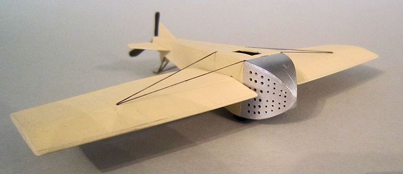
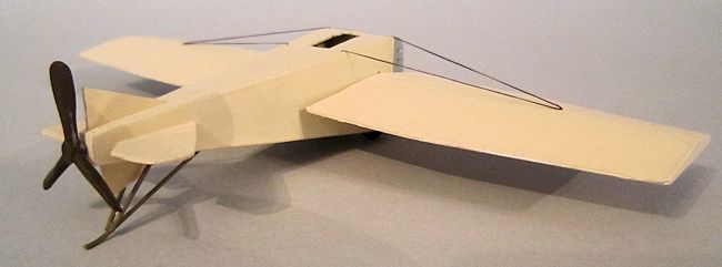
He was very active during the pre-WWI period, and designed, built and flew the legendary Gallaudet Bullet, a streamlined tail-dragger monoplane with pusher propeller, of which it was said at the time that it was twice as fast as any other biplane. The radial 100hp Gnôme twin-row rotary engine was in front, hidden behind a pointed streamlined nose, and the pilot straddled the drive shaft, on what was presumable a saddle-like seat. Not a comfortable position in the days before metal fatigue as known about. A snapped drive shaft could result in more than mechanical damage. And not helped by the lack of a windscreen, in spite of a top speed of 110 mph. He was seriously injured when he stalled his Bullet some 100 feet off the ground, severing an artery in his leg among other injuries, although he survived.
| THE KIT |
 I first
came across the Bullet while surfing the internet, especially the excellent
Russian website Their Flying Machines, see below for ref.
I first
came across the Bullet while surfing the internet, especially the excellent
Russian website Their Flying Machines, see below for ref.
There is also some good scale
plans on Flickr, see below also.
I downloaded the plans, scaled
them to 1/72, using the span and length information given, and ran off several
copies for my project. I had scratch built various parts for aircraft before,
including wings and fuselages, but had never scratch built a full aircraft
before. The Bullet appealed because it had a square fuselage, with no compound
curves, simple layout, no windscreen to be moulded, and no markings to rummage
around for.
| CONSTRUCTION |
Beginning with the fuselage all
four sides can be cut out using the plans as templates. My plastic card sheets
have been around a while and the labelling I put on them has long since rubbed
off, but I think it would be about 20 mil card. Not the thinnest, but thin
enough to be pliable without heat. You can make a few inner frames for support
from scrap offcuts, which I keep in a box from vacform projects. It all presents
no problems, although it is best to leave off the top decking for the moment,
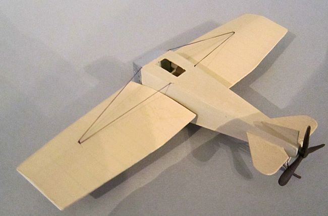
while you cut out the rectangular cockpit opening, and detail the inside of the
fuselage with a seat. I could find no
 pictures
of the interior so made do with a joystick and rudimentary dash with a couple of
dials. Most WWI aircraft had little more.
pictures
of the interior so made do with a joystick and rudimentary dash with a couple of
dials. Most WWI aircraft had little more.
Also, cut out a couple of
rectangles from the lower decking to accommodate the wheels. Most of these
are inboard and hidden by the fuselage sides, so a couple of sparebox wheels are
all that is necessary, painted tire black and left for later. Tires of this
period often used rubber which had no soot in it, and so were often shades of
grey. They even came in a pink colour, if you can live with that.
At the same time, the tail planes
can be cut from the same card. As far as I could see, the tail was all flying
and so there is no need to scribe any elevator lines.
I then discovered that it had been
built in 1/72 by Gabriel Stern, who is a far better scratch builder than I. And
so I shamelessly copied from his website a method he has of making wing ribs
show. Mark out the ribs with a pencil and metal rule on the underside of the
upper surface, using the plans and keeping them equidistant. And then run a biro
over the lines several times using the rule again. This will make a slight
raised line on the upper side of the wing, together with a black biro line which
will show through slightly, even after painting. It is simpler to do than
describe. So thank you Gabriel Stern, and I hope you have not patented your
method, just as Mr Gallaudet didn't patent his wings.
I cut the wing under surfaces to
size, and laid them flat, using some blue tack to keep them in place. The top
surfaces I cut accurately for the leading edge, but then extended the chord by ¼
inch or so at the rear, to allow for overlap when cambering the upper surface. I
then glued the leading edges together and allowed them to set, but with a very
thin length of plastic rod glued along the leading edge. This can be sanded down
to a sharper leading edge profile later, and defines the aerofoil section
 very well.
Then cut a length of larger diameter plastic rod and slide it into place where
the main spar would go, roughly one third of the chord width back from the
leading edge. Leave a half inch or so of the rod standing proud on the inner
edge of the wing, to serve as a locating pin later.
very well.
Then cut a length of larger diameter plastic rod and slide it into place where
the main spar would go, roughly one third of the chord width back from the
leading edge. Leave a half inch or so of the rod standing proud on the inner
edge of the wing, to serve as a locating pin later.
Then bend the upper surface around
the spar and glue the trailing edges in place, using clothes pegs as clamps.
There is no need of plastic rod for the trailing edge, but once set you will
need to trim the overlap from the upper surface and sand it all down to a thin
edge.
A word of warning, do not slide
the pegs too far inboard while the glue is setting, or you will gets surface
kinks in the upper surface. You may safely guess how I know this.
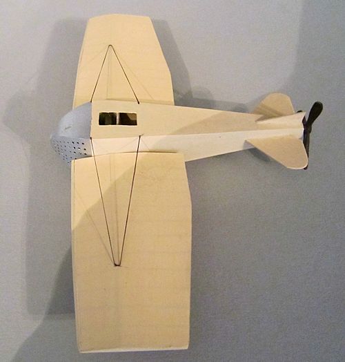
Turning back to the fuselage,
spray the nose area with the silver of your choice (Humbrol 11 here, from a
rattle can), take a deep breath and mark out all those ventilation holes. There
is no getting around this, as it is such a distinctive feature of the aircraft
and is one of those defining details. It makes the Bullet look a little like a
cheese grater, which has been got at by an interior designer.
 I used a
flexible plastic rule to pencil out an even spaced grid. Then take a twist drill
and use the smallest drill for the first row of holes. Then upgrade to larger
and larger drills as you progress toward the back. If you botch it, you will
have to go back and redo all the fuselage. So courage mon brave, and have a
stiff single malt to hand, either to brace yourself to the task in hand, or as a
reward for when you have finished. Or two glasses, one for each occasion.
I used a
flexible plastic rule to pencil out an even spaced grid. Then take a twist drill
and use the smallest drill for the first row of holes. Then upgrade to larger
and larger drills as you progress toward the back. If you botch it, you will
have to go back and redo all the fuselage. So courage mon brave, and have a
stiff single malt to hand, either to brace yourself to the task in hand, or as a
reward for when you have finished. Or two glasses, one for each occasion.
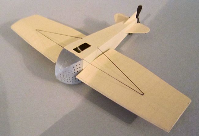
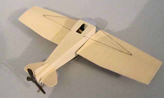
And now the bulk of it is over. Carefully align the wings to the fuselage, somewhere at the mid-height level. I splodged the spar ends with some felt tip marker just to get a rough idea of where the location holes should be drilled. Drill them, and fix the wings, noting that both leading and trailing edges stand proud of the fuselage. Then fix the tailplanes, fill the rear of the fuselage with a small square of plastic, scavenge an old propeller from the spares bin, sand it down to size, paint a dark brown, with varnish finish, and glue in place.
COLORS & MARKINGS
|
You are now entering the final
furlong. Mask off your beautifully drilled nose area, and then cover the rest of
the aircraft with the doped linen colour of your choice. I think I used
Lifecolor Sand FS33711,
 just for a
change from my usual Vallejo Buff.
just for a
change from my usual Vallejo Buff.
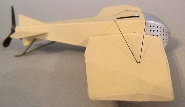
The three piece tail skid is cut
from plastic rod, making sure they are lengthy enough to keep the prop from
churning up the turf.
And note what an unusual
arrangement it is, to have a a pusher prop and a tail skid instead of a nose
wheel. Note also that the stance of the aircraft on the ground is horizontal,
perhaps tending toward slightly nose down.
Finally a couple of bracing wires from the cockpit area of the fuselage to the wings. You will find some variation in information here. Some plans show them as joining the wing with a small distance between them, some as joining at the same point. I chose the latter, using elastic thread, coloured with a black felt tip pen.
| CONCLUSIONS |
So
there you have a very elegant racer monoplane of revolutionary design from
before WWI, which I would recommend to anyone who wanted to dip their toes in
the waters of scratch building. Take your time, and measure everything very
carefully before you cut it, and this is one that will only take you the same
length of time as one of your super detailing projects. And it is your own, your
very own, not some kit that someone else has prepared for you.
| REFERENCES |
http://flyingmachines.ru/Site2/Crafts/Craft28652.htm
http://www.flickr.com/photos/sdasmarchives/4590482058/in/photostream/
Chris Peachment
November 2013
If you would like your product reviewed fairly and fairly quickly, please contact the editor or see other details in the Note to Contributors.