Jaeger Miniatures 1/48 Rumpler C.IV
|
KIT # |
|
|
PRICE: |
$42.50 |
|
DECALS: |
One aircraft |
|
REVIEWER: |
|
|
NOTES: |
Resin kit limited to 250 copies |
|
HISTORY |
The Rumpler Company is not well known, considering that it was an early entry into the fledging field of aeronautical engineering. Founded in 1906 by automotive engineer Edmund Rumpler, the company began to manufacture the Rumpler Taube, resulting in the company’s first military contract for Taube aircraft in 1910. In spite of the success of the Taube design, it was readily apparent by 1913 that the Taube design was hopelessly outdated. A new design was needed.
The first original Rumpler design was the Type 4A biplane, which was introduced in June 1914. This airplane broke the world record for flight duration that same year. The two seat C.I biplane soon followed in 1915. This airplane had better climb and speed performance than the preeminent Fokker EIII fighter plane that ruled the skies over the Western front at that time. This design evolved into the the Rumpler C.IV.
 The C.IV
resulted from wringing out aerodynamic improvements and weight reductions from
the original C.I. In 1916, the C.IV model was capable of flying for 3.5 hours,
climbing to 16,000 feet in 33 minutes, and achieving a top speed of 102 mph all
with a full combat load. Later models with improved engines could reach a
ceiling of over 22,0000 feet, thus allowing these reconnaissance aircraft to
simply “out fly” most allied fighters. While the weight reduction production
resulted in improved performance, it also resulted in weakening the structure of
the aircraft. Numerous “fixes” had to be applied over the aircraft production
cycle. Nevertheless, the Rumpler was a workhorse of German reconnaissance and
ground support aviation units until almost the end of the war.
The C.IV
resulted from wringing out aerodynamic improvements and weight reductions from
the original C.I. In 1916, the C.IV model was capable of flying for 3.5 hours,
climbing to 16,000 feet in 33 minutes, and achieving a top speed of 102 mph all
with a full combat load. Later models with improved engines could reach a
ceiling of over 22,0000 feet, thus allowing these reconnaissance aircraft to
simply “out fly” most allied fighters. While the weight reduction production
resulted in improved performance, it also resulted in weakening the structure of
the aircraft. Numerous “fixes” had to be applied over the aircraft production
cycle. Nevertheless, the Rumpler was a workhorse of German reconnaissance and
ground support aviation units until almost the end of the war.
|
THE KIT |
When Jaeger, a small company in Scotland, announced that it was introducing Rumpler C.IV in 1/48, I was a bit stunned. Not because it was some earth shattering announcement, but just that I realized I had never seen an offering of this particular airplane in that scale. The Rumpler is really a wonderful looking airplane, well documented in the literature, but also a workhouse of WW1 German aviation with over 2,200 aircraft delivered between September 1916 and January 1917 as listed in the serial number table of the Rumpler C.IV Data File. There is even an original example of this wonderful airplane in the Deutsches Museum in Munich, Germany!. Well, the oversight has been put to rest with the introduction of this wonderful kit, Jaeger's first-ever WW1 aircraft.
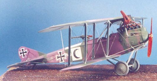
The kit consists of twenty eight resin and 9 white metal parts. No photo etch is included as most of the detail parts are cast resin. Resin parts include the wings, one-piece fuselage, tail feathers, internal cockpit, and some externals such as a flare rack and crew figures. The internal cockpit is nice. Getting inside the one-piece fuselage is a bit difficult for painting but not daunting. At least it allows one to practice some brushwork.
 I like the
resin cockpit details. Jaeger provides a nice aerial camera with fuselage trap
door so you can build a photo recon version of the airplane. White metal aerial
bombs are also provided so you can build a bomber version. The resin engine
provided as actually a casting of the top half of the engine. It sits in an
engine compartment in the single piece fuselage. It really looks good when
finished. Proper fit on the entire aircraft is essential and is something I did
not fully appreciate when I started out building this kit; there isn’t much
wiggle room when building.
I like the
resin cockpit details. Jaeger provides a nice aerial camera with fuselage trap
door so you can build a photo recon version of the airplane. White metal aerial
bombs are also provided so you can build a bomber version. The resin engine
provided as actually a casting of the top half of the engine. It sits in an
engine compartment in the single piece fuselage. It really looks good when
finished. Proper fit on the entire aircraft is essential and is something I did
not fully appreciate when I started out building this kit; there isn’t much
wiggle room when building.
Copper State models provides the flying surfaces. These castings are just superb. Thin and well detailed throughout, these pieces look just about perfect. Copper State also supplies the rear Parabellum machine gun, which is extremely detailed and looks just great when finished.
Overall, the resin detail is just wonderful. I can’t remember actually filling any resin bubbles. Some flash was present but it was almost insignificant when one considers other entries in the resin kit market as well as some of the “limited run” injected molded kits we stumble across. What flash did exist was mostly on the fine detail resin parts, such as the flare pistol.
The white metal parts consist of the interplane struts, cabanes, landing gear strut assembly, tail skid, prop, and some smaller parts.. The white metal is very well cast and of good quality. This is the first model I built that came equipped with white metal struts that I actually did not replace with bamboo.
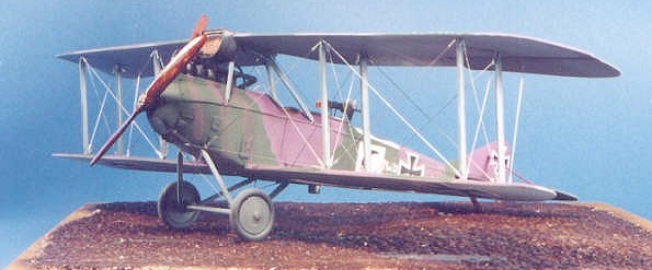
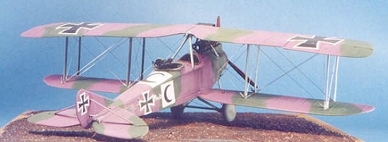
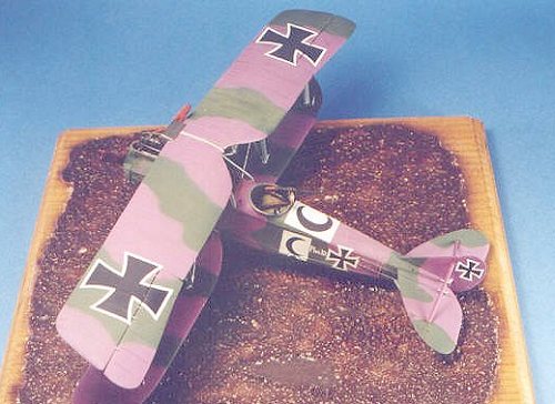
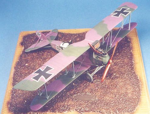
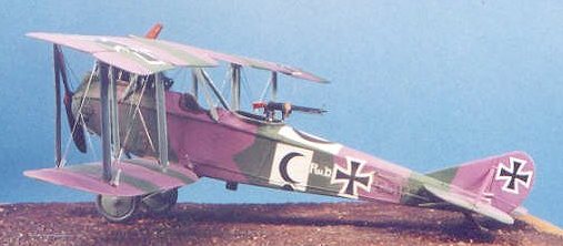
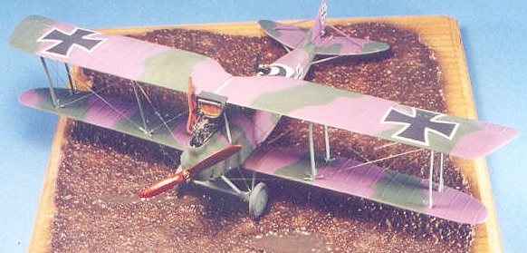
Microscale Decals are provided for one aircraft, that of Rumpler C.IV No. 8455/16 of the 2nd Marine Field Flieger Abteilung in 1917.
|
CONSTRUCTION |
As with most resin kits, the instructions provided for the build are minimal. Jaeger supplies a little 4-page booklet with a general text guide for assembly, along with 3 photographs of the model both partially and fully assembled. My initial problem was to match all the parts to the parts list. This was a bit difficult because the very small resin detail parts had a bit of flash on them that obscured what they really were. The same can be said for the small detail white metal parts. It took me all of about 30 minutes to sort this all out. One part I could never find was the flare pistol that is supposedly cast in resin. Perhaps it was missing, perhaps it was so flashed I could not perceive it as a pistol?
Fuselage:
 The fuselage is
a single piece casting with the cockpit interior hollowed out. This casting is
just superb. Excellent detail both on the outside and the inside. One thing I
really liked is that the fuselage walls around the cockpit are so thin you can
see light through it, with the shading provided by the cast-in structural
members. On the real aircraft, this area was fabric covered and the same
effect could likely be perceived depending upon how the aircraft was painted. I
thought that was so cool considering I have seen modelers sand the fuselage
almost paper thin on some injection molded kits in an attempt to achieve the
same effect.
The fuselage is
a single piece casting with the cockpit interior hollowed out. This casting is
just superb. Excellent detail both on the outside and the inside. One thing I
really liked is that the fuselage walls around the cockpit are so thin you can
see light through it, with the shading provided by the cast-in structural
members. On the real aircraft, this area was fabric covered and the same
effect could likely be perceived depending upon how the aircraft was painted. I
thought that was so cool considering I have seen modelers sand the fuselage
almost paper thin on some injection molded kits in an attempt to achieve the
same effect.
Most of the cockpit detail is assembled onto a two-piece resin floor that is fitted to the fuselage from the bottom. As you assemble the detail, make sure you dry fit the floor into the fuselage often. With camera, floor hatch and all that stuff installed to the floor assembly it would be a shame if some of the parts just hung over the edge enough so it wouldn’t fit inside the cockpit. The entire cockpit assembly took me no more than 2 or 3 hours to build, and a majority of that time was spent painting the interior of the one-piece fuselage and detailing out the cast-in fuselage members. Once the floor is installed, it fit nicely and model putty hid any seams. Fuselage finished.
Wings, Engine, Exhaust - General Fit:
Wings, engine, exhaust......why on earth did I lump all these together into one general heading? Because the wing fit affects the cabane fit, which affects the engine fit, which affects the exhaust fit. I found this out the hard way and actually lucked out some in that my “eyeball” technique and primitive wing jigs came through sufficiently for me to get an adequate fit.
Ok.... here’s where it starts. The lower wing attaches to the fuselage. As with all the resin kits I have ever seen there are no alignment pins!. The only guide is the low relief wing roots cast into the fuselage sides. The lower wings mount to these roots and I would strongly suggest you build a primitive jig to aid in the fitting of the wings. This becomes apparent when you realize that the fuselage floor you just glued in place has a high relief detail that will not allow the fuselage to sit flat on the table. I had to raise the fuselage up on a jig so it could sit plumb to my workbench with clearance for that bit of underside detail. I had detected this potential problem earlier and toyed with the idea of mounting the wing to the fuselage and then mounting the flooring. I gave up on this because the floor actually provides stiffening to the thin-cast fuselage in that area (remember - light can come through!). My fear in discarding this approach was that I would have the wings glued in with CA, they would be misaligned, and then I would have to stop for a few glasses of wine before I continued!. I decided to play it safe and go with a finished fuselage assembly to mount the lower wings to.
 I
double-checked the wing root casting to the scale drawings in the datafile and
also drew some alignment marks on a piece of paper that I taped my little jig
to. I glued the wings in place, making sure I eyeballed the angle of attack of
the wings to look about right. The lower wing angle of attack is critical
because it will affect the strut fit and upper wing angle of attack, which in
turn affects the mounting of the center cabane strut. If this seems
complicated, it really isn’t when you see the kit. You just have to plan ahead.
I
double-checked the wing root casting to the scale drawings in the datafile and
also drew some alignment marks on a piece of paper that I taped my little jig
to. I glued the wings in place, making sure I eyeballed the angle of attack of
the wings to look about right. The lower wing angle of attack is critical
because it will affect the strut fit and upper wing angle of attack, which in
turn affects the mounting of the center cabane strut. If this seems
complicated, it really isn’t when you see the kit. You just have to plan ahead.
The lower wings fit to the wing roots with just a bit of sanding. As per my usual procedure, I proceeded to fit the stabilizer and tail so I could putty the entire assembly at one time. The stabilizer pieces just glue to the fuselage without the aid of any pre-cast roots or anything else to align with. I used my data file drawings to pencil in mounting guides for these pieces.
After filling any seams I painted this assembly, set it aside for 24 hours, and proceeded to study the upper wing mounting.
Upper Wings:
The center cabanes are actually two white metal arcs glued together that meet above the centerline of the fuselage. Each upper wing half mounts to the side of this cabane. To get a good fit it becomes obvious that the cabane mounting will affect the angle of attack of the upper wing. My first gasp for air was at this point. Did my lower wing angle of attack match the upper wing? Yes - not perfect, but pretty good! Once I found I was clear of this potential disaster, I mounted the white metal struts to the underside of the upper wings and did about 10 dry fits to the cabane to see if the pre-drilled strut mounting holes in the lower wing aligned. Fit looked good and I attribute that to Jaeger’s excellent engineering rather than to my meager skill level. Before I committed to gluing in place I taped the upper wings to the cabane to fix alignment and then glued the struts to the lower wings.
 Engine.
The engine fit is tight. I fitted the engine to the fuselage after I mounted the cabane arcs, but before I mounted the upper wings. There is some engine plumbing to install here and doing that around mounted upper wings would be difficult. Here is where I noticed that my engine was not properly placed relative to the cabane struts because a dry fit of my exhaust assembly would not clear the struts and properly mount to the engine.
I finally yanked the engine out using CA remover and did lots of dry fits with double sided scotch tape and the exhaust to get a good fit. I ended up doing the plumbing around the upper wing mounts in the long run. I got a good fit, not perfect, but adequate. Notice that my engine is canted to the right a few degrees. No , Candice did not go blind. The actual engine was mounted in the aircraft that way to get it to fit!
Final Assembly:
Once past the engine exhaust fit, the airplane is essentially on short final! The only detail that took me awhile to assemble was Copper State Model’s 1/48 Parabellum machine gun. It is a resin and photo-etch gun assembly that looks great when finished. I have always had problems with very small photo etch, though I am getting better at it. I decided to persevere with the gun, but for those without the patience the CSM gun can be replaced with an Aeroclub white metal gun. My CSM gun took me about 4 hellish hours to build, but it looks a lot better than a white metal Aeroclub gun ever will.
|
PAINT & DECALS |
 Painting:
I used Poly Scale paints for the upper camo and Gunze for the underside. The model is painted per the kit instructions. For the Mauve, I used German Mauve, while the green is Dark Green. The pale blue underside and struts are done using Gunze RLM65 Hellblau. Nothing special to mention here. I Finished up with lots of Future for decal application.
Decals:
The decals went down with no problem, being MicroScale. I then applied another coat of Future.
Final Assembly:
I attached the landing gear, then proceeded to rig the model per the method outlined in my other reviews. Rigging is perhaps the hardest part of doing a World War I model, but it is the thing that makes the model "come alive."
|
CONCLUSIONS |
This kit is the first WW1 aircraft offering from Jaeger and I really like it. I do not have a vast amount of experience with resin kits, the Rumpler being my fourth one. I would not tackle this kit without having a few biplanes under my belt, but with careful dry fit and by thinking ahead for alignment, it shouldn’t be a problem for a moderately experienced injection molded modeler.
Jaeger and Copper State collaborated on this kit and the focus on quality shines brightly. I am looking forward to new Jaeger kits. If they ever decided to go injection molded they would push Hi-Tech offerings of the WW1 category into oblivion. This is a nice kit and it was a pleasure to build it. Not problem free, but lots of fun.
Copyright ModelingMadness.com
Thanks to Jaeger Miniatures for the review kit.Review kit courtesy of my kit collection.
If you would like your product reviewed fairly and fairly quickly, please contact the editor or see other details in the Note to Contributors.
Back to Reviews Page 2016