Copper State Models 1/48 Sopwith 1 1/2 Strutter
|
KIT # |
1011 |
|
PRICE: |
$74.95 |
|
DECALS: |
Two aircraft |
|
REVIEW : |
|
|
NOTES: |
Limited Run Resin Multi-media kit. |
|
HISTORY |
The Sopwith 1 ½ Strutter was one of the first mass produced aircraft from the famous Sopwith Aviation Company headed by Sir Thomas Sopwith in WWI. First appearing in combat in late 1915, it was the first British fighter with a synchronized forward firing Vickers machine gun. The Strutter was flown by many air forces during the war and was also produced in large quantities in France. The Stutter was frequently one of the first aircraft flown by many aces during the war, and Canadian ace Raymond Collishaw scored his first victories in the Strutter.
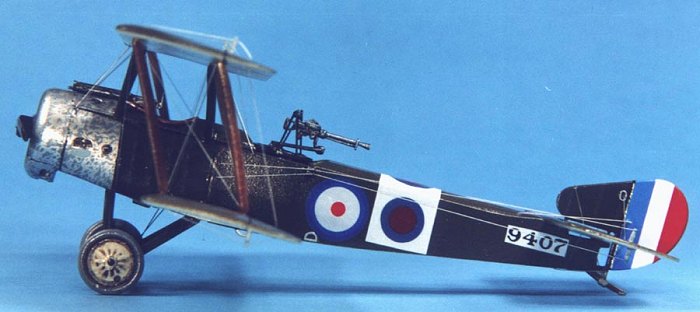
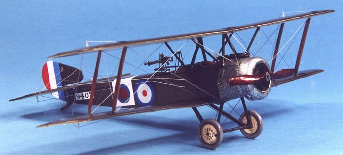
The aircraft modeled is a Sopwith 1 ½ Stutter flown by FSL Raymond Collishaw and gunner R.S. Portsmouth while with 3 Wing RNAS in late 1916.
|
THE KIT |
 Generally, I am less than enthusiastic about limited run kits since they
usually require the modeler to provide many components such as decals, detail
parts, etc. However, this kit from Copper State Models (CSM) (http://www.amug.org/~copperst/main.html)
contains most everything you need to build a great model straight from the box.
This is a true multi-media kit consisting of resin parts (8 items), white metal
castings (33 items), a photo-etch (P/E) fret (38 items), a set of British
instruments consisting of P/E bezels and acetate faces, a Clerget motor set
consisting of a white metal engine and P/E details, and complete decals for two
aircraft options. The resin casting is nicely done, highly accurate and
detailed, although a few pieces were plagued by tiny pinholes that needed
filling. CSM is to be commended for being one of the few vendors to accurately
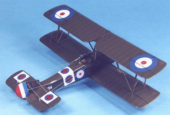
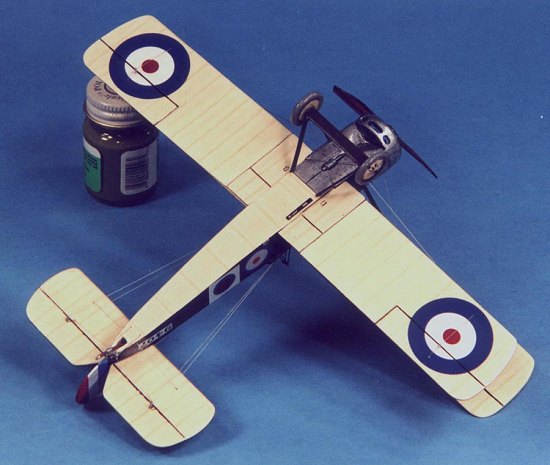
portray ribs on the top and bottom wing surfaces and getting the unique
"Sopwith tail section" correct. The detail engraved into the surfaces
is perfectly done.
Generally, I am less than enthusiastic about limited run kits since they
usually require the modeler to provide many components such as decals, detail
parts, etc. However, this kit from Copper State Models (CSM) (http://www.amug.org/~copperst/main.html)
contains most everything you need to build a great model straight from the box.
This is a true multi-media kit consisting of resin parts (8 items), white metal
castings (33 items), a photo-etch (P/E) fret (38 items), a set of British
instruments consisting of P/E bezels and acetate faces, a Clerget motor set
consisting of a white metal engine and P/E details, and complete decals for two
aircraft options. The resin casting is nicely done, highly accurate and
detailed, although a few pieces were plagued by tiny pinholes that needed
filling. CSM is to be commended for being one of the few vendors to accurately
portray ribs on the top and bottom wing surfaces and getting the unique
"Sopwith tail section" correct. The detail engraved into the surfaces
is perfectly done.
The white metal castings are the only disappointment in the kit. Many of the surfaces were pitted and rough and required filling and sanding, and the casting of some items (such as the Vickers) was poor. To be fair, the P/E provides replacements for many of these casting shortcomings and I would have used the P/E pieces any way. The P/E is very nicely done, but is a bit stiff to bend and greatly benefits from annealing. The decals are beautiful, printed by Micro Scale, however the blue on the roundels probably is a bit too light. Since I was finishing this model as Collishaw’s aircraft, I substituted various decals from my stash and did not use the kit supplied ones. There are really no instructions provided with the kit, but an experienced modeler with a few kits under the belt would not find this as a difficulty. Complete three-view drawings along with building notes, part lists, color painting schemes, and a short history are provided to assist the modeler.
|
CONSTRUCTION |
The first job up was to separate and clean up the resin and white metal parts. An examination of the edges of the resin pieces under bright light indicated many small air bubbles underneath the surface so care must be exercised when cleaning up the resin. In addition, it is imperative that the center lower wing section (which forms the floor of the fuselage) be dry fitted in place, as the fit was "cranky". Filing and sanding was needed to get a correct fit of this critical part. After a quick wash in warm soapy water, I then pre-painted all the parts. The interior linen surfaces were painted Polly Scale French Beige and the wood framing and surfaces were painted Testors Military Brown. The metal surfaces were given a coat of Humbrol MetalCote Gloss Aluminum. Since the cockpit openings are quite large, .005 music wire was used to simulate the interior bracing wires. Everything was given a light wash of burnt umber before assembly.
The instrument panel is provided for in white metal, however I ditched this in favor of a scratch built piece of .010 card since it would be easier for mounting the instrument faces provided in the kit. I followed the instrument panel drawing and instructions for general placement of the instrument faces, first drilling appropriate size holes for the bezels and attaching the acetate faces to the backside of the card and the bezels to the front with white glue. I then attached a backing plate of unpainted white card to the backside of the instrument panel to help show the faces. Unfortunately, even though the cockpit opening is quite large, the instrument panel mounts very high in the fuselage to be almost unviewable! Of note, the cockpit detail provided for in the kit is very nice and while further detailing can be done, there is plenty of detail straight from the box. I then attached all the interior pieces to their respective fuselage piece and superglued the aft fuselage together allowing the center section to "free float" with some masking tape. I applied accelerant to the fuselage join and quickly went to work with sanding sticks to clean up the join. Unfortunately this process caused quite a few pinholes to appear on the fuselage bottom that had to be filled later.
 I had noticed in dry fitting that the fit of the center lower wing section
was critical to establishing the forward fuselage width. To get this dimension
correct I installed the P/E firewall in place with white glue to set the forward
width. This plan worked to perfection since there were some gaps in the side
walls that would have made the forward section of the fuselage too narrow if I
had "forced fit" it into place with superglue. That would have caused
some serious assembly problems further down the line. Tacking the pieces
together with masking tape first to get the right dimensions and then applying
superglue to hold permanently worked quite well. This did leave some small gaps
that required filling with putty between the fuselage floor and sidewalls but
this was very easy to correct and allowed a good fit of the metal cowl and upper
fuselage piece.
I had noticed in dry fitting that the fit of the center lower wing section
was critical to establishing the forward fuselage width. To get this dimension
correct I installed the P/E firewall in place with white glue to set the forward
width. This plan worked to perfection since there were some gaps in the side
walls that would have made the forward section of the fuselage too narrow if I
had "forced fit" it into place with superglue. That would have caused
some serious assembly problems further down the line. Tacking the pieces
together with masking tape first to get the right dimensions and then applying
superglue to hold permanently worked quite well. This did leave some small gaps
that required filling with putty between the fuselage floor and sidewalls but
this was very easy to correct and allowed a good fit of the metal cowl and upper
fuselage piece.
The horizontal stabilizer was next superglued to the fuselage turtle deck and assembly of the upper wing started. A tip is to enlarge the openings for the cabane struts in the white metal center section, this will ease fit problems when mounting the upper wing. I drilled .020 holes through the white metal center section and corresponding wing butt and mounted brass pins to provide a secure mating surface for the wings. The upper wings have a small amount of dihedral to them that was provided for by bending the brass pins slightly. The wing was then taped to the modeling bench with two small pencils taped under each wing tip before superglue was applied to bond the wings to the center section with the correct dihedral. The pins also provide for much more strength than could be accomplished by butt joining. I then stuffed tissue paper into the cockpit opening, gave all the parts a quick wipe down with Polly’s Plastic Prep and went off to the paint shop.
|
PAINT & DECALS |
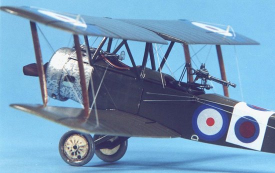
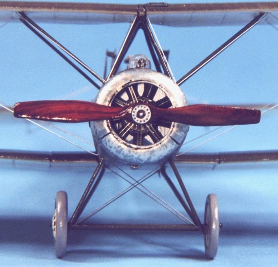
The paint scheme of this aircraft consisted of a PC10 doped upper wing/fuselage over clear-doped linen (CDL) undersurfaces with a machined metal cowl. Xtracolor RFC Green (X22) was used for the PC10 surfaces and Xtracolor RFC Doped Natural Fabric (X21) was used for the undersurfaces. All paints were airbrushed. After a short drying time, I masked the surfaces and airbrushed Floquil Gun Metal for the metal surfaces. After the paint scheme cured for a day, I shot a light coat of Future to prepare the surface for decaling and the "riffled metals" finish. A distinctive feature that shows up in most photographs of Strutter’s is the riffled metal pattern on the cowl and metal surfaces. To reproduce this effect I sparingly and finely applied a random silver pattern using a ZIG Painty Silver Oil based Paint Marker (available at most art supply stores) over the gun metal surfaces. The Painty has a fine petal shaped tip that allows for very fine-drawn lines that closely approximates this effect, which is actually caused by machining aluminum. I am not a talented enough painter and could never accomplish this effect with a paintbrush.
 Bob Pearson had provided me with a profile of Collishaw’s Stutter and
fortunately I had all the decals needed in the spare decal stash (never throw
anything away, you never know!). Of note, there are differing profiles of this
aircraft flown over an extended period of time by Collishaw and I arbitrarily
chose one scheme. The fuselage number was done using dry transfer numbers on
white decal paper. I applied Micro Sol setting solution and all the decals
responded quite well and melted into the surface with no permanent wrinkling.
After drying overnight, I wiped the decals off with a Polly S Plastic Prep to
remove any residue and after drying, I shot a light coat of Future over the
decals to seal them.
Bob Pearson had provided me with a profile of Collishaw’s Stutter and
fortunately I had all the decals needed in the spare decal stash (never throw
anything away, you never know!). Of note, there are differing profiles of this
aircraft flown over an extended period of time by Collishaw and I arbitrarily
chose one scheme. The fuselage number was done using dry transfer numbers on
white decal paper. I applied Micro Sol setting solution and all the decals
responded quite well and melted into the surface with no permanent wrinkling.
After drying overnight, I wiped the decals off with a Polly S Plastic Prep to
remove any residue and after drying, I shot a light coat of Future over the
decals to seal them.
For weathering, I chose to accentuate the engraved panel lines and surface detail with a light burnt umber oil wash.
I then sealed everything with a light coat of PS Flat Finish to provide a
surface for pastel application. I then used a pastel pencil to lightly highlight
the rib detail on the wings/tail surfaces using a light brown pastel pencil on
the undersides and an off-white pastel pencil on the upper surfaces. I use
Derwent pastel pencils and they are quite easy to use, just lightly draw on the
surface to be highlighted and blend with artists blending stump. A very nice,
subtle effect can be achieved with these pencils that is much easier for me than
dry brushing. Lastly, I applied a heavy burnt umber oil wash to the wheels and
control surface joins.
|
CONSTRUCTION CONTINUES |
Now that the painting and weathering is complete, it’s time to finish off the construction. The lower wings were installed in place with brass pins and then superglued for strength and the cabane struts were glued in place with 5-minute epoxy. A simple jig constructed from Lego blocks was built to hold the upper wing in place with the correct alignment and the white metal interplane struts were superglued in place to the lower wing and then the upper wings were attached with superglue. Usually, alignment of the upper and lower wings on a biplane is a bother, however on this kit everything just snapped into its correct place. Lastly, the outside "W" struts were cut from Contrail strut stock and superglued in place.
The Vickers machine gun provided in white metal is poorly cast, however the P/E parts provided in the kit correct this problem. I separated the breech and threw the rest away! Using hypo tubing plus the P/E jackets and detail pieces I was able to rebuild the gun to a beautiful state.
 Assembly of the landing gear was easy and it was time to put on the tail fin.
I installed .020-styrene rod into the base of the tail fin and drilled
corresponding holes into the stabilizer. After carefully aligning the tail fin
to provide a gap at the aft end I then superglued the rods into place, using the
longer rear rod to double as the kingpost. Assembly of the Scarff Ring and Lewis
gun was challenging. Fortunately I had a detailed drawing of the arrangement
from my personal library; otherwise I would have never been able to figure it
out, as the instructions are somewhat vague and confusing! Lastly, I installed
the propeller (Martin Digmayer carved wood available through CSM) and tailskid
and I was almost done with only the rigging to be completed.
Assembly of the landing gear was easy and it was time to put on the tail fin.
I installed .020-styrene rod into the base of the tail fin and drilled
corresponding holes into the stabilizer. After carefully aligning the tail fin
to provide a gap at the aft end I then superglued the rods into place, using the
longer rear rod to double as the kingpost. Assembly of the Scarff Ring and Lewis
gun was challenging. Fortunately I had a detailed drawing of the arrangement
from my personal library; otherwise I would have never been able to figure it
out, as the instructions are somewhat vague and confusing! Lastly, I installed
the propeller (Martin Digmayer carved wood available through CSM) and tailskid
and I was almost done with only the rigging to be completed.
I use .006-fishing line painted silver and use a "through-hole" rigging method. I basically drill a hole with an #80 bit (the smallest, about .0135) all the way through the wing at each of my rigging exit points. I try to minimize the number of exit points and run as many lines through them when possible. After securing one end to a partially drilled hole (not all the way through) with superglue, I then run the line out through the exit hole. I weight the end of the line with a pair of hemostats to pull tight by letting it hang down and apply a small drop of superglue to secure it. Let cure for about 30 seconds and then unhook the hemostats and proceed to the next wire. Repeat until done! After letting the entire rigging cure for at least an hour, I then take a brand new Exacto blade and trim flush with the wing surface. I then sand the exit holes flush and apply a spot of touch-up paint to cover. That's it, simple, cheap, and fast. In addition, it also provides a small amount of structural integrity. I can rig a whole airplane in under an hour! Can't do that with wire!
Finally, the model is almost done. The last step is to airbrush the final clear coat. I used Polly S Satin Finish as it provides an appropriate not too glossy, not too dull surface that photographs well.
|
CONCLUSIONS |
While a bit expensive (~$75), this is an incredibly detailed and accurate model that can be built pretty much straight out of the box. While several aspects of the build were quite challenging due to the limited run nature of the kit, the end results are very beautiful. I would recommend this kit to advanced modelers and to intermediate modelers looking for a new challenge.
|
REFERENCES |
Albatros Productions LTD, Windsock Datafile #34, Sopwith 1 ½ Strutter
Copyright ModelingMadness.com. All rights reserved. No reproduction in any form without express permission from the editor.
If you would like your product reviewed fairly and quickly, pleasecontact the editor me or see other details in the Note to Contributors.
Back to Reviews Page 2025