Eduard 1/48 Albatros D.V
|
KIT # |
8013 |
|
PRICE: |
$ |
|
DECALS: |
See Review |
|
REVIEW & |
|
|
NOTES: |
|
|
HISTORY |
Like most modelers, I have a large inventory of about 50+ unbuilt kits cluttering up my work space and am usually faced with a confusing choice about which kit to build next. I am always on the lookout for modeling an aircraft of historic interest and the old Eduard Albatros DV/DVa kit caught my eye when I saw that Hermann Goering’s DV was one of decal options.
Hermann Wilhelm Goering (AKA Göring) was mostly known as one of Adolf Hitler’s closest associates and as Commander-in-Chief of the Luftwaffe during WWII. What is lesser known is that he was also a highly decorated WWI pilot with 22 kills, awarded the famed "Blue Max" (Pour le Merite), and commanded the elite JG 1 squadron (Jasta Richtofen) at the end of the war.
 The son of a senior Army officer, Goering was born in
Rosenheim, Bavaria on 12 January 1893. Following in his father’s footsteps, he
was commissioned in the Prussian Army in June 1912. During WWI he was first
posted with an infantry regiment but severe rheumatoid arthritis required
hospitalization and ended his infantry career. While recovering, Goering was
convinced by his close friend Bruno Loerzer (41 kills, 8th ranking
German ace) to transfer to the German Army Air Service. In late 1914, Goering
completed training as an observer with FEA 3, and joined his friend Loerzer in
1915 with FFA 25 often flying as his observer. In 1915, Goering completed
training as a fighter pilot and was posted to KEK Metz (Verdun front) where he
earned his first kill on 16 November 1915. After postings at Jasta 5, 7, and 26,
he eventually was awarded command of Jasta 27, and was selected to command JG 1
from July 1918 until the end of the war. As a highly decorated war hero with the
Pour le Merite, Knights Cross, and Iron Cross (1st and 2nd
Class), Goering was seen as arrogant and liked to live a pompous lifestyle with
extravagant feasts and clothing (which alienated most of the men under his
command) and was clearly ambitious for future advancement.
The son of a senior Army officer, Goering was born in
Rosenheim, Bavaria on 12 January 1893. Following in his father’s footsteps, he
was commissioned in the Prussian Army in June 1912. During WWI he was first
posted with an infantry regiment but severe rheumatoid arthritis required
hospitalization and ended his infantry career. While recovering, Goering was
convinced by his close friend Bruno Loerzer (41 kills, 8th ranking
German ace) to transfer to the German Army Air Service. In late 1914, Goering
completed training as an observer with FEA 3, and joined his friend Loerzer in
1915 with FFA 25 often flying as his observer. In 1915, Goering completed
training as a fighter pilot and was posted to KEK Metz (Verdun front) where he
earned his first kill on 16 November 1915. After postings at Jasta 5, 7, and 26,
he eventually was awarded command of Jasta 27, and was selected to command JG 1
from July 1918 until the end of the war. As a highly decorated war hero with the
Pour le Merite, Knights Cross, and Iron Cross (1st and 2nd
Class), Goering was seen as arrogant and liked to live a pompous lifestyle with
extravagant feasts and clothing (which alienated most of the men under his
command) and was clearly ambitious for future advancement.
After the war Goering served as a test pilot for the Fokker Company in Holland and joined Hitler’s fledging Nazi party in 1922. Given command of Hitler’s infamous SA Brownshirts stormtroopers, Goering was badly wounded in the Munich beer hall putsch of 1923. His wounds, along with his previous arthritis forced his dependencies on a variety of narcotics and it was widely known that Goering was a morphine addict. Along with Hitler’s rise to power, Goering became President of the Reichstag, Prime Minister of Prussia, and eventually the Commander of the Luftwaffe during WW2. Goering also served as one of the founders of the infamous Gestapo and played a key role in the creation of concentration camps, at first for political dissidents and eventually part of Hitler’s Final Solution. Goering survived the war and was found guilty of conspiracy to wage war, crimes against peace, war crimes, and crimes against humanity during the Nuremberg War Crimes Trial. Sentenced to death by hanging he managed to escape the hangman’s noose when several hours before his scheduled execution time, Goering committed suicide by taking a cyanide capsule.
|
THE KIT |
 The kit is Eduard’s Albatros DV kit (8013) which also
includes all the necessary parts for the Albatros DVa variant. It is not
currently in production, but kits can still be found (I got mine dirt cheap
since it is discontinued, $10 USD). It is a mixed media kit and consists of
injected molded plastic (33 parts), two sheets of photo-etch detail parts (36
items), finely cast white metal engine components (4 parts), an acetate sheet
for the windscreen and instrument dials, and the usual Czech printed decal sheet
with options for Goering’s Jasta 27 Albatros DV, or von Hipple’s Jasta 5
Albatros DVa. The plastic parts have significant amounts of flash/mold lines
that require clean up and do not have any locating pins or holes and these must
be drilled. The instruction sheet is the usual four page diagram assembly with
marked color painting guidelines, and is clearly indicated with the
modifications needed to build the DVa variant. In addition, a one page color
sheet is provided showing the final painting and decaling schemes for both
variants (unfortunately, no color information is provided with this sheet so you
are on your own with regards to color selection, however, the colors are fairly
accurately rendered on my sheet).
The kit is Eduard’s Albatros DV kit (8013) which also
includes all the necessary parts for the Albatros DVa variant. It is not
currently in production, but kits can still be found (I got mine dirt cheap
since it is discontinued, $10 USD). It is a mixed media kit and consists of
injected molded plastic (33 parts), two sheets of photo-etch detail parts (36
items), finely cast white metal engine components (4 parts), an acetate sheet
for the windscreen and instrument dials, and the usual Czech printed decal sheet
with options for Goering’s Jasta 27 Albatros DV, or von Hipple’s Jasta 5
Albatros DVa. The plastic parts have significant amounts of flash/mold lines
that require clean up and do not have any locating pins or holes and these must
be drilled. The instruction sheet is the usual four page diagram assembly with
marked color painting guidelines, and is clearly indicated with the
modifications needed to build the DVa variant. In addition, a one page color
sheet is provided showing the final painting and decaling schemes for both
variants (unfortunately, no color information is provided with this sheet so you
are on your own with regards to color selection, however, the colors are fairly
accurately rendered on my sheet).
|
CONSTRUCTION |
I started with my usual warm, dish soap water wash of the plastic, metal, and photo-etch components and followed with a cold water rinse. Pat dry with a paper towel and let dry overnight. The wash does really help on Eduard kits, especially on the photo-etch parts. I then pre-painted all the parts as indicated in the instructions, with the exception of the fuselage walls, bulkheads, floors, and engine mount floor which I covered with Tauro wood grain decal (the only wood grain decal still in production). The stringer detail on the fuselage sidewalls were then hand painted Testors Model Master (TMM) French Chestnut and given a light wash of burnt umber.
Assembly of the fuselage components was accomplished using super-thin superglue. Assembly proceeded as described in the instructions, however two problems arose. First, the pilot yoke/stick assembly as indicated in the instructions is incorrect as it is reversed. Further on in the instructions is the view, which shows the assembly of the sub-assemblies into the fuselage, that view is correct. Of course, I followed directions exactly and did not notice this until after I assembled the part! I left mine incorrect as Eduard photo-etch is very fragile and I did not want to destroy the yoke. The result is that my yoke sits much too far forward in the cockpit, but you don’t really notice it unless you look closely! The second problem involves the installation of the bulkheads. Early Eduard models are not known for good engineering and fit problems arise. Mine was no exception, and since I built the cockpit as sub-assemblies the bulkheads would not fit correctly. It is very difficult to get a good fit of the magazine to its bulkhead and then to its correct opening in the fuselage. A lot of grinding with a Dremel erased these fit problems but in the future I will assemble the bulkheads to the fuselage first and then assemble the remaining parts. I then skipped over the instruction sequence for the machine guns and feed belts and started on the engine.
 The white metal engine components are very nicely cast, with
little clean-up work needed. I painted them, assembled them together, and then
gave the whole assembly a heavy wash of black. I installed the engine floorboard
to the fuselage side, wrapped the top half of the engine (exhaust stack was not
installed yet) in parafilm, and installed the engine into the fuselage with
superglue.
The white metal engine components are very nicely cast, with
little clean-up work needed. I painted them, assembled them together, and then
gave the whole assembly a heavy wash of black. I installed the engine floorboard
to the fuselage side, wrapped the top half of the engine (exhaust stack was not
installed yet) in parafilm, and installed the engine into the fuselage with
superglue.
I then closed up the fuselage, said bad words about the bulkhead fit problem, fixed them as described, and used liquid cement to glue the fuselage halves together. I then separated (cut) the control surfaces from the upper wing, horizontal stabilizer, and tail fin as I was going to position these in accordance with the way the controls were glued into the cockpit (left turn). Next, I glued with liquid cement the headrest fairing (I believe very few Albatros’ used this, but Goering’s did), the tail fin, the skid fairing, and lower wing to the fuselage. When I removed the stabilizer control surfaces, I was left with a right and left hand part for the stabilizer. In order to insure a correct join to the fuselage, I installed small pieces of hard music wire into the stabilizers and carefully drilled corresponding mounting holes into the fuselage. This worked perfectly and with a little bit of tweaking I cemented the stabilizers to the fuselage in perfect alignment that did not require any putty. I then cleaned up the separated control surfaces with sanding sticks and used liquid cement to rejoin them to their correct position and locations. All joins were then sanded smooth, and putty was used to fill some minor gaps in the lower wing to fuselage join. Then I drilled all of the rigging, strut, and landing gear mounting holes as described in the instructions. Next stop was the paint shop.
The model was painted, decaled, and weathered as described in the following subsections and then final assembly took place.
I installed the interplane and cabane struts into place using relatively large amounts of super-thin superglue. This is done to insure a relatively fragile model does not explode in later life! The cabane struts were glued to the fuselage body in correct spacing for the upper wing using a caliper to exactly set the distance and the interplane struts were glued to the bottom of the top wing. Basically, by applying small drops of super-thin superglue carefully around the strut to form a small bead around the strut base you can make the model much stronger. Do not use an excessive amount, just enough for a thin bead. If you use super-thin superglue carefully applied, you can form a perfect bead around the strut base. This will be later painted over in touch up and my "secret" hiding technique discussed later will help hide the superglue.
 I then installed the radiator assembly to the lower portion of
the upper wing and the aileron actuators (parts PE 18 & 24) as described in
the instructions. Next I drilled small holes in the radiator to fit short
sections of corresponding diameter lead fuse wire painted copper for the
radiator to engine piping. The fuse wire is available at hardware stores and
also flyfishing stores (used to weight nymphs) and is much easier to work with
than copper tubing because it bends and cuts easily. Superglue the fuse wire to
the radiator in the drilled holes and you will get a very sturdy join.
I then installed the radiator assembly to the lower portion of
the upper wing and the aileron actuators (parts PE 18 & 24) as described in
the instructions. Next I drilled small holes in the radiator to fit short
sections of corresponding diameter lead fuse wire painted copper for the
radiator to engine piping. The fuse wire is available at hardware stores and
also flyfishing stores (used to weight nymphs) and is much easier to work with
than copper tubing because it bends and cuts easily. Superglue the fuse wire to
the radiator in the drilled holes and you will get a very sturdy join.
Now it was time to return to the machine guns. Assemble the guns as shown in the instructions. A tip to ease assembly is to use a correct length of rod (not a little piece as shown) superglued to a drilled hole into the gun breech opening. By carefully aligning this rod, mounting and aligning of the cooling jackets will be much easier, just superglue them to the bottom of the rod. Make sure you anneal (heat in a flame until red hot) the jackets and you will be rewarded with a truly circular jacket. Roll the jackets around the correct size circular rod (styrene rod works) to get a perfect jacket. Place the jacket seam to the bottom and no one will even see it! I painted the machine guns in Testors Metallizer Gun Metal and dry brushed with Floquil Gun Metal. Good luck in mounting the photo-etch ammo feeds, even more luck is required to get them in the proper shape shown into the magazine! I also could not mount the cover (PE 15) as shown in the instructions and ended up reversing it.
Now onto the fun part, putting on the top wing! Actually, this task went smoothly with no problems. Since the cabane struts are made of metal and already fixed in the correct position on the fuselage (remember using a caliper to set the actual distance) the top wing snapped into place in the correct position. I placed the upper wing on the work bench and turned the fuselage upside down to mount it. First set the interplane struts into place in their correct holes (remember to drill them out), then flex the metal cabane struts into their respective holes and bingo, the wing is in place. I used small rubber bands to help hold both wings in place and then checked alignment of the top to bottom wing. When all was to my liking, superglue the struts to wing using the bead technique described above. A word of caution, let the glue cure fully before moving the model and you will be rewarded with a relatively strong top wing join.
Now on to the next challenge, installing the landing gear! Installing landing gear on early Eduard models is a challenge at best and extremely frustrating at worst. Since there are really no locating pins and holes to speak of, many people install metal pins into the ends to help ease this task. I use a simpler method in that I build a simple jig. My jig is nothing but a small block of styrofoam packing material that comes in protective packaging of electronics goods. One TV and you are set for life! Take a small block of styrofoam and mark the width of the landing gear on it. Carefully measure all dimensions and mark them on the block to maintain the correct angles. Push the legs of the landing gear into the block and set the approximate width of the landing gear axle. Then place the axle into place on the legs (you did remember to drill those holes?) and after carefully aligning everything glue it in place. Let the glue fully cure then paint the assembly black, let dry, and remove it from the block. Glue one leg into place with superglue, let set, then glue the remaining legs into place. Use the superglue bead technique described for the struts and you will be rewarded with a relatively strong set of landing gear. Lastly install the painted wheels into place on the axle with superglue, and the tail skid.
Carefully install the exhaust stack, propeller, and propeller spinner with superglue. I drilled out the exhaust stacks, painted them Testors Metallizer Burnt Iron and then applied a heavy wash of Rustall. The propeller was painted by using a base coat of dark yellow, and successive light dry brushing using a rake brush of TMM raw sienna, raw umber, burnt sienna, and burnt umber to replicate the wood grain. The rake brush does a fairly good job of replicating wood grain without resorting to decals, which are a pain on a small part like a prop.
Install all the remaining pieces (but not the top wing radiator and aileron actuators) as indicated in the instructions to prepare for the next fun job of rigging a WWI biplane! Truthfully, rigging an airplane is not difficult. It is time consuming and tedious. First you need a plan. You should have a rigging plan in place before you even start construction of the model so you can pre-drill holes and plan for obstruction problems. Study the instructions carefully and figure out where every rigging wire needs to go. Each kit will be different and will have a different plan. For example, the Eduard Albatros has photo-etch cabane struts that are a pain to drill holes in since the metal deforms easily. In this case, I saw that six rigging wires pass through each cabane. I drilled a small hole with my smallest bit (#80, .0135 in) through the lower wing and attached four long rigging wires through it with extra thin superglue. The nice thing about the Albatros is it has a small metal plate (PE 6) to cover this hole from the bottom of the wing. I then ran a wire to the forward upper interplane strut, one to the rear upper interplane strut, one wire through the forward upper cabane strut around the wing attachment piece then down to the bottom of the interplane strut, and lastly one wire through the rear upper cabane strut around the wing attachment piece then down to the bottom of the interplane strut. I no longer drill holes through struts for rigging as it may pull out in time. I wrap the end of the wire completely around the strut and secure it with a tiny drop of extra thin superglue using the bead technique described for struts. Rig the rest of the model as indicated on the instruction sheet.
For rigging wire I use a product sold in sewing shops called invisible thread (which is the same as monofilament fishing line) that is .004 inches in diameter (which is the correct scale size). It is easy to use, just paint it whatever color you like (I finally found a use for those Testors paint markers that I bought! Flat black is best for appearance, silver is the more realistic color but doesn’t show up well on pictures), is easy to pull taut (use a hemostat as that vital third hand to keep the wire taut), is easy to thread around/through stuff, and more importantly, you can trim it flush easily with a new XACTO blade. No more metal wire or stretched sprue for me!
Finally, the model is almost done. The last step is to install the remaining parts to the upper wing (top wing radiator and aileron actuators).
|
PAINT & DECALS |
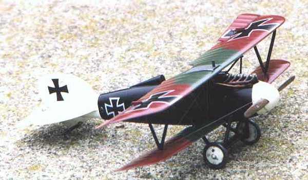
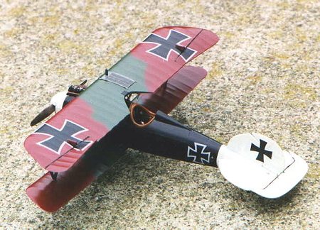
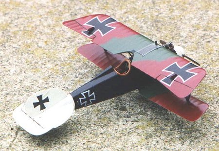
This version of the Albatros DV dates this airplane in mid-1917 while Goering was flying for Jasta 27. Goering’s DV is a fairly simple paint scheme, consisting of a black fuselage and struts with a white nose and tail section. The wings were typical of early Albatros’ DV, with an underside of light blue, and a camouflage of mauve and green on the top side. For this airplane I used a mix of acrylic and enamel paints.
As mentioned above, all painting was done after completion of the fuselage and attachment of the lower wing fairly early in the construction process. I started first by airbrushing the spinner, wheels, front fuselage and rear fuselage Gunze Sangyo Aqueous Hobby Color (GS) Off White (H21). Even though this is an acrylic paint, it took over a week to fully cure to the point where I could mask for the black color. In the meantime, I shot the underside of the wings with a home brewed Humbrol enamel blend for the underside blue. I still don’t have the color right; it needs a bit more green to it.
 I then ran into a painting problem that I have not experienced
before. I sprayed the top of the wings with Polly Scale (PS) Mauve thinned with
PS Airbrush Thinner, but severe clogging of the airbrush produced a stringy,
clumpy mess on the wings. I cleaned up the wings with household window cleaner,
which is an excellent acrylic paint remover and reshot the wings with PS Mauve
thinned with distilled water with the same result. More window cleaner cleaned
up that mess and removed all of the paint. It turns out this was a blessing in
disguise since in my opinion the mauve color is much too light. I then reshot
the wings with Humbrol enamel WWI Purple (#107), which unfortunately is a tad
too dark (next time I will add 10-20% white to lighten it). Next up was a
freehand spray to match the camo pattern on the instruction sheet with TMM
French Khaki which is a near perfect match for the green used on German WWI
wings. By now, the white had fully cured and I masked off the wing, tail
section, and front fuselage for the final spray of GS Gloss Black (H2). Again,
it took a full week for the black to cure and I still had a problem that will be
described later. I then masked the wheel covers off with masking tape trimmed
with a sharp XACTO blade and shot the tires with Tamiya Dark Gray (XF24). In
preparation for decaling, I sprayed a light coat of Future on the upper wing.
Since the remaining colors were all gloss, they did not get a coat of Future.
I then ran into a painting problem that I have not experienced
before. I sprayed the top of the wings with Polly Scale (PS) Mauve thinned with
PS Airbrush Thinner, but severe clogging of the airbrush produced a stringy,
clumpy mess on the wings. I cleaned up the wings with household window cleaner,
which is an excellent acrylic paint remover and reshot the wings with PS Mauve
thinned with distilled water with the same result. More window cleaner cleaned
up that mess and removed all of the paint. It turns out this was a blessing in
disguise since in my opinion the mauve color is much too light. I then reshot
the wings with Humbrol enamel WWI Purple (#107), which unfortunately is a tad
too dark (next time I will add 10-20% white to lighten it). Next up was a
freehand spray to match the camo pattern on the instruction sheet with TMM
French Khaki which is a near perfect match for the green used on German WWI
wings. By now, the white had fully cured and I masked off the wing, tail
section, and front fuselage for the final spray of GS Gloss Black (H2). Again,
it took a full week for the black to cure and I still had a problem that will be
described later. I then masked the wheel covers off with masking tape trimmed
with a sharp XACTO blade and shot the tires with Tamiya Dark Gray (XF24). In
preparation for decaling, I sprayed a light coat of Future on the upper wing.
Since the remaining colors were all gloss, they did not get a coat of Future.
The decals supplied with the kit are typical Czech/Propagteam decals. Super thin and super fragile. I won’t dare try von Hipple’s "Blitz" scheme with these decals, as the large arrow will surely tear. I mostly succeeded in applying the decals. Lots of water underneath the decal helps, but I still managed to tear small bits off the larger decals. A close look at the German crosses will see some of this minor tearing. I looked in my spare decal box for a similar style German cross, but unfortunately they were all Czech/Propagteam so I decided to leave well enough alone! After a short drying period of about an hour, I applied MicroSol setting solution to get the decals to melt into the surface and the articulated control surfaces. I repeated with a second coat of setting solution to get all the decals fully down. They responded very well to the setting solution with no permanent wrinkling. After drying overnight, I wiped the decals off with a moist cloth with a bit of soap to remove any residue and after drying I shot a very light coat of Future thinned with rubbing alcohol (50-50 mix) over the decals to seal them.
WEATHERING
For weathering, I chose to accentuate the lightly engraved panel lines and surface detail with a Derwent watercolor pencil in light gray. Watercolor pencils are ideal for this task since the standard wash technique does not work very well since the panel lines/detail is so lightly engraved. They can be used atop a gloss or flat finish and are quite easy to use. Just trace lightly around the object or within the panel line and then lightly smooth over with a water dampened cotton swab or paint brush for a subtle effect. If you mess up, correction is easy and you just wipe off the bad area with water soaked cotton swab. Much easier than a regular colored pencil as I can never stay within the panel lines or erase completely my mistakes! Blending is also easy with a damp brush. I then shot a very light coat of Testors Dullcote to seal the pencil detail (it is very fragile) and to prepare the surface for pastel weathering.
Unfortunately, the Dullcote reacted poorly with the gloss finish acrylic paint and melted the finish and cracked a bit around the engine. Next time I am sticking with acrylic flat coats. The cracked areas actually looked realistic since I reasoned that those areas were subjected to heat from the engine and likely to have flaws (at least that is my excuse!) and the melted finish would be cured by my hiding technique. I then used a pastel pencil to lightly highlight the rib detail on the wings/tail surfaces using a light gray for the darker colors and a dark gray for the lighter colors. I use Derwent pastel pencils and they are quite easy to use, just lightly draw on the surface to be highlighted and blend with artists blending stump. A very nice, subtle effect can be achieved with these pencils. I then randomly applied some ground up burnt umber pastels with a soft brush to simulate dirt staining on the lower surfaces. Lastly, I applied a heavy burnt umber oil wash to the wheels and control surface joins.
I then finished final assembly of the models as described above. Lastly, I lightly touched up by hand painting with the appropriate colored paints all flaws and the areas that were covered in superglue including strut/rigging attachment points. Next was a technique I learned that helps hide minor flaws in a model finish caused by superglue and painting successive coats. It is very simple, just spray the entire model with several coats of a mix of equal parts Future, Tamiya Flat Base (X21), and rubbing alcohol. This will hide almost all minor flaws in the finish, but will not cover major flaws so it is not a substitute for poor modeling technique. Finally, several coats of straight Future was shot to achieve the final glossy finish common to most WWI aircraft. Now, drink a favorite beverage and admire your good work!
|
CONCLUSIONS |
This was a project that took about a month to complete due mainly to the paint curing time. However, I actually only spent about 20 hours on the build, which is about average for me on a WWI model. I highly recommend this kit for experienced builders, as it is a very accurate and good representation of the important Albatros DV/DVa airplane. Less experienced modelers could have a successful build with some care but the size of some of the photo-etch parts (less than 1 mm!) coupled with fit problems discussed earlier will make it a challenge. In fact, this was the very first Eduard model I completed without losing/ruining some of the small photo-etch parts! Since the model has been discontinued it may be tough to find, but the price on it is likely to be very attractive. This was undoubtedly the best and most accurate $10 (USD) model I have ever built and I returned to the hobby shop and purchased his entire remaining stock so look for more gallery entries in the future!
|
REFERENCES |
Squadron/Signal Publications, Albatros Fighters In Action, SS1046, $8.95
Grub Street, Under The Guns Of The German Aces, $35.00
Albatros Productions LTD, Windsock Datafile, Albatros Fighters, $25.00