Wingnut Wings 1/32 Fokker D.VII (OAW)
|
KIT #: |
32030 |
|
PRICE: |
$79.00 SRP (shipping included)
|
|
DECALS: |
options |
|
REVIEWER: |
Otis
Goodin |
|
NOTES: |
Finally a good, accurate Fokker DVII in 1/32 scale. |
Wingnut Wings continues to crank out the
kits. Among their latest offerings is the long awaited Fokker DVII in Fokker,
Albatros and OAW versions. Soon they will be releasing the Fokker DVIIF.
The Fokker DVII is probably the definitive fighter
aircraft of WWI. It is generally considered the best fighter of the war, and
Germany certainly hoped it would turn the tide of the war in their favor.
Shortly after its acceptance by the German Air Service, Fokkers were ordered
built in large numbers. To provide as many of the aircraft as possible, Albatros
was also ordered to produce them under license from Fokker. Utilizing their
Johannisthal (Albatros) and Schneidermuhl (Ostdeutsche Albatros Werke or OAW)
plants, Albatros eventually produced twice as many DVII as Fokker did. Each
manufacturer had their own unique design characteristics that distinguished
their aircraft. For instance, OAW machines incorporated louvered fuselage engine
panels as well as upturned carrying handles.
 Initially,
the DVII was plagued by the usual unforeseen problems familiar to any new design
(see Boeing’s 787), in this case engine overheating and fires. By the time the
bugs were worked out the war was pretty much lost, although it’s doubtful one
weapon could have changed the course of the war (nuclear weapons
notwithstanding). During its time in service, however, the Fokker DVII certainly
created a noteworthy reputation for itself, so much so that it was the only
aircraft specifically required to be turned over to the Allies by the Versailles
Treaty. If fitted with the best engines available at the time, the 200 hp
Daimler-Mercedes or the even more powerful BMW IIIa, the Fokker DVII
demonstrated handling characteristics that far exceeded anything in the air. The
DVII was known to “hang on its prop” without stalling allowing it to fire upward
at steep attack angles. The lack of wing rigging reduced drag during flight, and
the aircraft was also sturdy in a dive, unlike the Albatros DV which was known
to shed its wings. Following the war, Fokker DVII were found in service in a
number of countries, and several survive today in museums around the world.
Initially,
the DVII was plagued by the usual unforeseen problems familiar to any new design
(see Boeing’s 787), in this case engine overheating and fires. By the time the
bugs were worked out the war was pretty much lost, although it’s doubtful one
weapon could have changed the course of the war (nuclear weapons
notwithstanding). During its time in service, however, the Fokker DVII certainly
created a noteworthy reputation for itself, so much so that it was the only
aircraft specifically required to be turned over to the Allies by the Versailles
Treaty. If fitted with the best engines available at the time, the 200 hp
Daimler-Mercedes or the even more powerful BMW IIIa, the Fokker DVII
demonstrated handling characteristics that far exceeded anything in the air. The
DVII was known to “hang on its prop” without stalling allowing it to fire upward
at steep attack angles. The lack of wing rigging reduced drag during flight, and
the aircraft was also sturdy in a dive, unlike the Albatros DV which was known
to shed its wings. Following the war, Fokker DVII were found in service in a
number of countries, and several survive today in museums around the world.
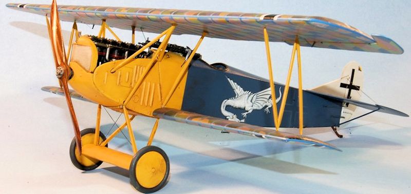
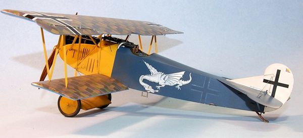
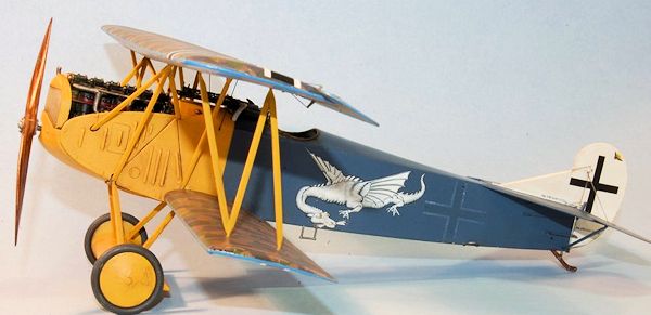
The aircraft that is the subject of this article was
flown by Wilhelm Leusch and featured a fire breathing dragon on the fuselage
inspired by an Unterberg & Helme company advertisement. Leusch was made
 commander
of Jasta 19 in October 1918 and scored 5 victories. He was only 29 when he died
in a glider accident in August 1921.
commander
of Jasta 19 in October 1918 and scored 5 victories. He was only 29 when he died
in a glider accident in August 1921.
The Wingnut Wings OAW
version offers 4 more options for DVIIs: (1) 4198/18 flown by Karl Ritscherle,
(2) 4523/18 flown by Rudolph Stark and featuring his familiar lilac markings,
(3) the colorful light blue and green marked Fokker of Franz Buchner, and (4)
the black and white striped DVII flown by Ulrich Neckel. You are given plenty of
decals to do the job including 4 and 5 color lozenge for wings and fuselage,
along with rib tapes if needed. Almost everything you need to do a complete
model of the Fokker DVII is present in the kit, except for rigging material.
Since modelers are so individualistic in their choices for rigging material I
can understand the omission.
I was eager to start construction on this 1/32 scale
Fokker DVII, certain that the small amount of rigging would enable me to finish
it in about two weeks. I had heard that one needed to be very careful in the
construction process, reading and following all the instructions and taking into
consideration the precise engineering of the kit. No problem, I thought. Two and
a half months later I finally put the finishing touches on the Fokker, having
learned several things about the kit and my modeling skills in the process (but
more on that later).
Construction begins in
the cockpit, attaching the rudder pedals and control stick to the cockpit floor.
Next the seat is attached to a linen covered frame, and the seat cushion is
added to the seat. Framing is added to
 the sides
of the seat for support, and this assembly is attached to the cockpit floor.
This is a good time to add the photo etch seatbelts if you plan to use them. Be
sure to anneal them to make them flexible to work with. I try to pose my
seatbelts in as realistic a manner as possible which to me means that they are
not evenly spaced on the seat, they are folded on themselves in random
arrangements, and the belts “hang” on the seat in such a way as to look like
cloth belts weighted down by buckles.
the sides
of the seat for support, and this assembly is attached to the cockpit floor.
This is a good time to add the photo etch seatbelts if you plan to use them. Be
sure to anneal them to make them flexible to work with. I try to pose my
seatbelts in as realistic a manner as possible which to me means that they are
not evenly spaced on the seat, they are folded on themselves in random
arrangements, and the belts “hang” on the seat in such a way as to look like
cloth belts weighted down by buckles.
Next assemble the ammo
box, machine gun mounts and fuel tank. Attached to the fuel tank are some spouts
and a gauge. These assemblies are then attached to a firewall that backs up to
the engine area. Following this you are instructed to assemble the cockpit and
forward fuselage framing, into which are placed the seat and aforementioned
assemblies. Attached to the cockpit framing are the air pump for pressurizing
the fuel tank, throttle control assembly, and the compass which is completed by
adding the decal and topping it off with clear parts cement for the glass cover.
It’s not being overly dramatic to say that this frame assembly is probably the
most important part of the whole model because so much is attached to it and
depends on it being installed correctly. Take your time here and to paraphrase
that famous saying, “Measure twice, glue once.”
Next assemble the
instrument board to which are attached a starting magneto and several switches
and instrument decals. Next are added more machine gun mounts along with the
tachometer and some extra cockpit framing. I found these a little tricky to
attach. You have the option of adding an altimeter to either side depending on
the version you are building. If you have specific questions there are several
color photos of the Memorial Flight Association DVIIF reproduction in the
instructions.
Somewhere in this
process you will want to add the cockpit rigging to the rudder pedals, control
column, and fuselage frame. Instructions also call for aileron control rigging
to be added to the end of the control column and threaded upward through small
holes in the fuselage where they ultimately connect to the underside of the top
wing. I didn’t see any practical way to do this with all the construction
remaining to be done so I left this part out. I later attached rigging from the
top wing through the small holes in the fuselage, but it didn’t connect to the
control column. Ultimately it’s not visible, but I’m sure a purist or two out
there will succeed in making it work.
 Next
to be added to the framing are engine mounts and some extra framing to help
support the engine. Following this, attention is turned to the engine where you
have a choice of either the 180hp or 200hp Daimler-Mercedes. The main difference
is in the intake manifold and the 200hp engine was called for in the DVII
version I was building so that’s what I went with. The instructions give you
full color shots of the engine that you can use as a reference for adding detail
if you like; however you can end up with a nice engine just by assembling it and
painting it as instructed. I installed the engine in the framing, but left off
the exhaust until later.
Next
to be added to the framing are engine mounts and some extra framing to help
support the engine. Following this, attention is turned to the engine where you
have a choice of either the 180hp or 200hp Daimler-Mercedes. The main difference
is in the intake manifold and the 200hp engine was called for in the DVII
version I was building so that’s what I went with. The instructions give you
full color shots of the engine that you can use as a reference for adding detail
if you like; however you can end up with a nice engine just by assembling it and
painting it as instructed. I installed the engine in the framing, but left off
the exhaust until later.
The interior framing
is pretty full at this point and the next step is to install it in the left
fuselage half. Do a lot dry fitting using both fuselage halves to make sure that
the interior fits as it should and the fuselage halves close up. Once satisfied,
glue the two halves together at the top only trapping the interior framing
inside the fuselage. Once the top is dry, turn the fuselage over and glue the
stitching to the bottom, taking care not to use too much glue. Any gaps in the
fit of the stitching can be resolved with Mr. Surfacer or cyanoacrylate. It took
me several attempts to seal up the seam in the top of the fuselage. I used
putty, Mr. Surfacer, super glue, then putty again and so on. The problem I kept
having was the seam would reappear after a couple of days and I would have to go
through the process all over again. I spent two weeks off and on fixing the seam
only to have it reappear several times after I had painted the fuselage. I would
have to remove most of the paint, fix the seam and then repaint. The ironic
thing was this was about the only seam to fill on the whole model. Builder error
I’m sure, but I’ve got to find a better way of filling seams.
Following this you are
instructed to assemble the radiator, chin cowl and piping which is then glued to
the front of the fuselage making sure to connect the radiator piping to the
engine. I found this to be a troublesome piece because if I connected the
radiator piping to the front of the engine then there would be a large gap
between the chin cowl and the underside of the aircraft. If I fixed the gap I
couldn’t make the radiator piping fit to the front of the engine. I’m sure this
was also a case of builder error, but I eventually removed the piping that
connected to the front of the engine and glued the assembly in place without the
gap. I then added a piece of stretched sprue to substitute for the piping I
removed and attached it to the radiator
 and
engine.
and
engine.
Next up were the
machine guns. Wingnut provides both photo-etch and non PE options for the guns.
I chose to use the photo etch and they went together pretty well. The mistake,
however, was installing them now. I should have waited closer to the end because
there is a lot of handling of the aircraft left to do and occasionally I would
inadvertently grab or bump the guns, bending the photo etch cooling jackets or
breaking off the plastic parts and having to reglue them.
I left off the
exterior panels until later, not having decided just what parts of the engine I
wanted to show. Next I assembled the wings and the landing gear. The wings were
painted a medium gray and then covered in Future to provide a slick surface for
the lozenge decals. The landing gear and wheels were painted and set aside. I
attached the tailplane assembly, although I left off the fin and rudder until
later.
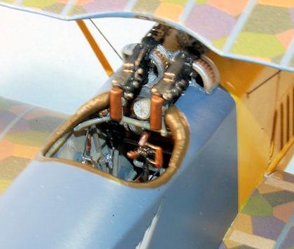
The interior was
painted using a variety of colors. The fuselage framing, pilot’s seat and some
instruments were painted Model Master Acryl RLM Gray. Instrument decals were
added as indicated. The cockpit floor and instrument board were painted Acryl
Tan and then given a wash of Griffin’s Burnt Umber for a wood appearance. The
ammo boxes were painted Aluminum as was the fuel tank and firewall. The spouts
were painted Polly Scale Copper. The seat cushion was painted Leather
highlighted with Burnt Umber. The seat belts were painted Gunze Sail Color and
the buckles RLM Gray. The engine was painted Aluminum with Gun Metal cylinders.
Polly Scale Copper was used to highlight a few items like the air pump and
carburetor details. Metallic Gray was also used. Once done it was given a wash
of Burnt Umber, as was the entire engine housing area.
 The
fuselage interior was painted gray and sprayed with Future to prepare it for
application of
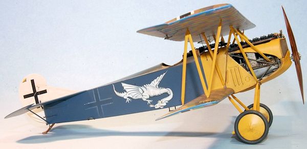
the reverse lozenge decals. The exterior of the fuselage was
painted in Model Master Dunkelblau RLM 24 (dark blue) and Chrome Yellow. It
takes several coats of the yellow to cover. Once satisfied with the paint job, I
coated part of the fuselage in Future and applied the crosses. I then lightly
sprayed some more Dunkelblau over the crosses to “blue” them down. Once
satisfied, I sprayed some more Future and applied the dragon decals. Once that
had set up I applied some Model Master Clear Satin to the fuselage.
The
fuselage interior was painted gray and sprayed with Future to prepare it for
application of
the reverse lozenge decals. The exterior of the fuselage was
painted in Model Master Dunkelblau RLM 24 (dark blue) and Chrome Yellow. It
takes several coats of the yellow to cover. Once satisfied with the paint job, I
coated part of the fuselage in Future and applied the crosses. I then lightly
sprayed some more Dunkelblau over the crosses to “blue” them down. Once
satisfied, I sprayed some more Future and applied the dragon decals. Once that
had set up I applied some Model Master Clear Satin to the fuselage.
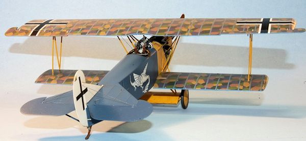
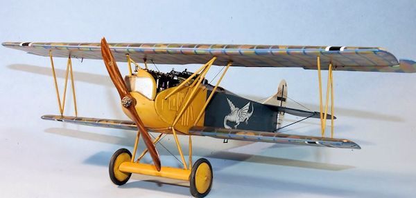
Next I turned my attention to the wings which were
covered in 5 color lozenge top and bottom. Once the lozenge set up it was time
to apply the blue rib tapes over the lozenge rib tapes already in place. Wingnut
provides the rib tape decals already cut to the various sizes provided, making
this job much easier. The most difficult part is applying rib tapes to the edges
of the wings, but with care the job can be done with little problem. I recommend
cutting the rib tapes into smaller pieces and applying them. You will find it
necessary to use decal solvent. I used a mix of Micro Set and Sol which worked
pretty well and didn’t damage the decals. I also applied the smaller wing
decals.
Wingnut informs us that many DVIIs applied a coat of
brown tinted dope to their lozenge surfaces to tone down the vibrant colors. I
had never heard of this before but it does explain the photos which show little
contrast among the various lozenges in the fabric. When I went to the NASM in
Washington, DC in 2011 I noticed that the color of the lozenge fabric on the
Fokker DVII there was more muted than that on the Albatros DV. I suspect that
the brown dope accounts for this effect. Wingnut instructs us to create a brown
dope by mixing Tamiya Clear with Tamiya Flat Earth in a 10:1 ratio. Before
applying it I emailed Richard Alexander at Wingnut for some specifics and he
clarified that, on the wings, it should only be applied to the top surface of
the wings. I applied it as he instructed and was pleased with the result. Once
the brown glaze had dried I sprayed some Future on the wings and then applied
the wing crosses. I then coated the wings with Clear Satin to tone down the
gloss.
Once the wings and fuselage assemblies were mostly
complete, it was time to install the wings and struts. I had previously sprayed
all the wing struts Chrome Yellow (several coats). Somewhere along the way I
lost the rear left cabane strut so I had to make a replacement out of plastic
card. Using the other as a guide I was able to assemble one that was pretty
close to the original. I installed the N struts and the three pronged cabane
struts but left off the rear cabanes
until the top wing was on. As I attempted to attach the
top wing I noticed that the N struts would not line up properly. I could fit one
side but not the other. With the top wing attached to the three pronged cabane
struts, I decided to remove the N struts and reinstall them. I broke the “feet”
off of one N strut while removing it so I had to replace them with plastic rod
which I super glued to the bottom of
 the N
strut. I was able to make the N struts fit this time so I then proceeded to
install the rear cabane struts. I installed the one original cabane strut which
didn’t fit so well. It appeared to be a little long. I decided to install the
other cabane strut and then check them. Once I installed the other strut the
first one snapped in two under the pressure. I was about to do the same. But, I
took a deep breath and nervously lined up the strut, cut away a portion and
reattached the broken pieces with super glue. Once dry I sanded the super glue
until it was smooth, applied some primer and, when dry, some more Chrome Yellow
paint. All in all not too bad of a repair job. But don’t look too close.
the N
strut. I was able to make the N struts fit this time so I then proceeded to
install the rear cabane struts. I installed the one original cabane strut which
didn’t fit so well. It appeared to be a little long. I decided to install the
other cabane strut and then check them. Once I installed the other strut the
first one snapped in two under the pressure. I was about to do the same. But, I
took a deep breath and nervously lined up the strut, cut away a portion and
reattached the broken pieces with super glue. Once dry I sanded the super glue
until it was smooth, applied some primer and, when dry, some more Chrome Yellow
paint. All in all not too bad of a repair job. But don’t look too close.
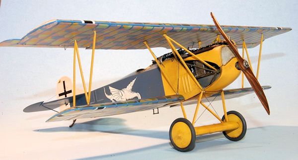
Once the wings were on
I attached the engine cowlings I wanted to use. I decided to use only the
cowling that fits directly under the exhaust on the right side, leaving the
engine visible for inspection. On the left side I attached one of the oval
louvered panels and left off the top part of the cowling. Following this I
attached the fin and rudder assembly, to which I had earlier applied the decals.
The fin on the DVII was offset slightly to the left to counteract the engine
torque. I attached the exhaust after first painting it Model Master Jet Exhaust,
then drybrushing it Metallic Gray, Rust and Dark Gray around the opening. I next
attached the landing gear assembly which had been painted Chrome Yellow as well.
The wheels were finished in Schwarzgrau then highlighted with some lighter gray
and brown. I rigged the landing gear using EZ Line fine and Bobs Buckles.
Rigging was also applied to the tailplane, control horns and ailerons. The final
rigging was the aileron control lines that run from the underside of the top
wing into the fuselage. I used wire for this, painted Gun Metal. Compared to the
usual WWI plane, rigging this was a piece of cake. The prop was last and it was
painted in Tan and Red Brown to resemble the laminations, then overpainted with
Griffin’s Burnt Umber. Once dry it was given a coat of Future for the decals,
then Futured again once they were dry.
Another winner from Wingnut Wings, the Fokker DVII
will undoubtedly be their biggest seller for some time to come. It’s not
easy
to build, but with patience and care you can build the best model of a Fokker
DVII you have ever built. I still have to pinch myself to believe that we are
living in the golden age of WWI aircraft modeling. Many thanks to Richard
Alexander at Wingnut Wings for answering my many questions, and to the whole
Wingnut team for the great models they are producing.
Wingnut Wings Fokker
DVII instructions
Fokker DVII
Aces of World War One, Part Two,
Norman Franks and Greg VanWyngarden, Osprey Publishing, 2004.
Otis
Goodin
April 2013
If you would like your product reviewed fairly and fairly quickly, please
contact
the editor or see other details in the
Note to
Contributors.
Back to the Main Page
Back to the Review
Index Page