Wingnut Wings 1/32 Fokker D.VII (alb)
| KIT #: | 32027 |
| PRICE: | $79.00 |
| DECALS: | options |
| REVIEWER: | Otis Goodin |
| NOTES: | This kit is now out of production, but examples may be obtained on eBay, etc. at much higher prices. |
| HISTORY |
As everyone knows by now, the Fokker DVII is the most highly regarded
German fighter to come out of WWI. Appearing in 1918 it quickly established
itself as one of the best aircraft of the war . Unfortunately
 for Germany, it
arrived too late and in too few numbers to alter the course of the war.
Nevertheless, it remains an iconic symbol of the advances in aircraft design and
function that took aviation from humble beginnings to advanced and deadly
capabilities in a few short years.
for Germany, it
arrived too late and in too few numbers to alter the course of the war.
Nevertheless, it remains an iconic symbol of the advances in aircraft design and
function that took aviation from humble beginnings to advanced and deadly
capabilities in a few short years.
The Fokker DVII was so popular and in such demand that the German Idfleig ordered it built, not only by Fokker, but also by OAW and Albatros under license from Fokker. Often the OAW and Albatros aircraft were of higher quality than the Fokker built machines, as Fokker’s quality control was sometimes lacking. There were subtle differences among the manufacturers in such things as engine panels, lozenge application, lifting handles, etc., but any version of the DVII was a highly desired machine.
| THE KIT |
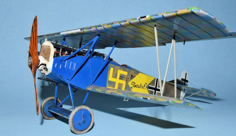
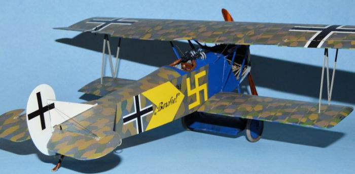
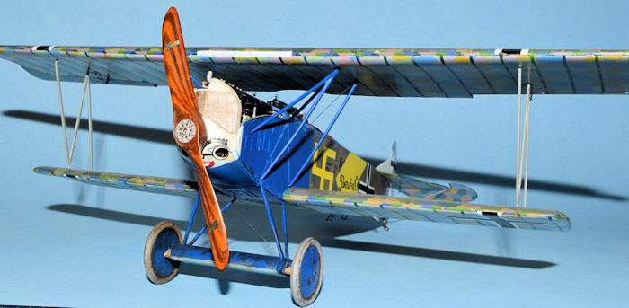
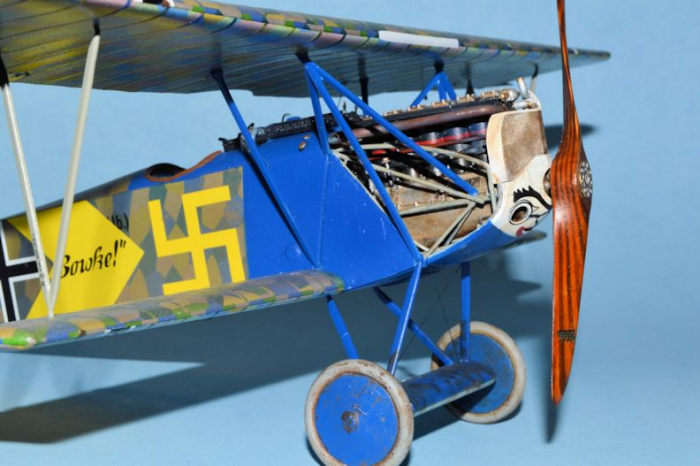
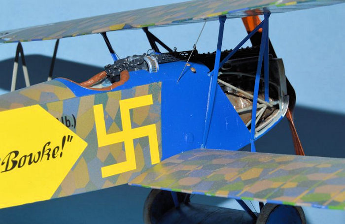
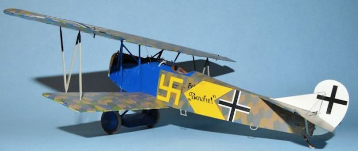
When Wingnut Wings introduced its highly anticipated Fokker DVII kits in November 2012 they released not one, but three separate versions of the aircraft, featuring versions made by Fokker, OAW, and the version reviewed here, Albatros. A few months later they also released the DVII F version featuring the highly desirable BMW engine, and have since released an early Fokker version. The Albatros kit contains 212 parts spread over 7 sprues plus a clear parts sprue. There are six sheets of decals including four containing both four and five color lozenge. There is also a photo etch panel containing seat belts and Spandau machine gun jackets. Also included are the Wingnut Wings kit instructions, a 34 page glossy booklet containing not only instructions but several black and white and color photographs that serve as valuable references for construction. The kit contains parts and decals allowing the builder to choose from among five separate aircraft: (1) Fokker DVII (Alb) 611/18, flown by Uffz. Harbers of Jasta 73 in 1918; (2) Number 817/18 flown by Fritz Blumenthal of Jasta 73, featuring white engine panels and the name “Nickchen IV” on the fuselage; (3) an aircraft flown by Richard Kraut of Jasta 63 in October and November 1918; (4) Carl Degelow’s DVII featuring a black fuselage with a white stag painted on it, and (5) the aircraft featured in this article, a DVII flown by Hermann Pritsch of Jasta 17, featuring the word or name “Bowke” in a yellow fuselage chevron. This aircraft also features a yellow swastika which, prior to the 1930s, was considered a universal good luck symbol, and was used by both sides during WWI.
 This led me to do some additional research into the
history of swastikas, and I learned some fascinating information. The first
known use of swastikas dates back some 15,000 years where they appeared on
engraved objects from the Ukraine such as bowls and religious symbols. Later,
swastikas were found in Bronze Age carvings and ceramic pottery dating back to
6000 BC, and swastikas found on the Indian subcontinent date back to 3000 BC. It
is theorized that use of the swastika moved from east to west where they
eventually showed up in Scandinavia, Europe, and the British Isles. Swastikas
have also been found on pottery in archeological digs in Africa, the Northern
Caucasus, and in various locations in China. Swastikas were used as symbols on
temples, pottery, coins, entrances, documents, and in rituals. Throughout its
history the swastika has been considered a universal symbol of fortune, good
luck, well-being, life cycles, eternity, and light. By the early 20th
century it was used worldwide as a symbol of good luck and success. It’s no
surprise then that it would be a popular symbol for fighter pilots to use as
they took to the skies against their foes.
This led me to do some additional research into the
history of swastikas, and I learned some fascinating information. The first
known use of swastikas dates back some 15,000 years where they appeared on
engraved objects from the Ukraine such as bowls and religious symbols. Later,
swastikas were found in Bronze Age carvings and ceramic pottery dating back to
6000 BC, and swastikas found on the Indian subcontinent date back to 3000 BC. It
is theorized that use of the swastika moved from east to west where they
eventually showed up in Scandinavia, Europe, and the British Isles. Swastikas
have also been found on pottery in archeological digs in Africa, the Northern
Caucasus, and in various locations in China. Swastikas were used as symbols on
temples, pottery, coins, entrances, documents, and in rituals. Throughout its
history the swastika has been considered a universal symbol of fortune, good
luck, well-being, life cycles, eternity, and light. By the early 20th
century it was used worldwide as a symbol of good luck and success. It’s no
surprise then that it would be a popular symbol for fighter pilots to use as
they took to the skies against their foes.
| CONSTRUCTION |
Construction begins in the cockpit where the first step is to paint the fuselage interior walls to prepare it for the application of “reverse” lozenge camouflage decals. Assembly of the cockpit commenced with the floor to which were attached the rudder pedal assembly and the control column. The seat was attached to the rear cockpit screen, and seatbelts were added to the seat. I used HGW fabric seatbelts which I find to be easier to use and more realistic than photo etch seatbelts. Following this the ammo magazine box and gun mounts were assembled, attached to the empty magazine belt box, to which was attached the fuel tank and Maximal fuel gauge. Finally, the entire assembly was attached behind the engine firewall.
The next step was to assemble the cockpit framing to which are attached
throttle controls and a hand pump for pressurizing the fuel tank. The framing
was then attached to the rear cockpit screen assembly. Once dry the engine/ammo
assembly was then added to the forward section of the framing. Also added to the
frame was a compass positioned by the pilot’s seat to which is added a detailed
compass decal. I topped it off with a drop of clear parts cement to represent
the glass cover. Finally, the instrument
 panel and rear Spandau gun mounts were
attached to the framing along with some crescent shaped framing parts to
strengthen and surround the pilot seating area. These are a bit tricky to attach
but necessary for a complete cockpit. The WNW instructions include lots of
pictures to give you a good idea of what things should look like when complete,
including pictures of the life size Memorial Flight DVIIF.
panel and rear Spandau gun mounts were
attached to the framing along with some crescent shaped framing parts to
strengthen and surround the pilot seating area. These are a bit tricky to attach
but necessary for a complete cockpit. The WNW instructions include lots of
pictures to give you a good idea of what things should look like when complete,
including pictures of the life size Memorial Flight DVIIF.
There is a small amount of internal rigging to attach to the rudder pedals and control column, as well as some “X” rigging for the frames. I accomplished this with EZ Line and a few drops of CA glue. The instructions call for some rigging to be attached to the end of the rudder pedal assembly to pass through the fuselage and up to the underside of the top wing. I didn’t see any way to accomplish this with all the construction and painting remaining so I left this off until later. I ultimately applied a modified version of this rigging using some stiff wire attached to the wing underside and passing through the fuselage; however, it did not attach to the rudder pedal assembly and doesn’t show anyway. No harm, no foul.
Engine mount framing was added to the forward part of the cockpit assembly, and construction began on the engine. WNW provides a very nice engine that is ripe for super detailing; or you can just assemble as directed and you will still end up with an attractive engine that looks good in the model. There are good painting and decal additions that will make the engine look realistic, along with some great color photos to assist with detailing. Four of the five versions in the kit use the 200 hp Daimler-Mercedes engine, and one uses the 180 hp version. The main difference is the air pump and intake manifolds used and the instructions point this out. The kit featured in this article used the 200 hp version. I decided to leave the engine out until the fuselage assembly and painting were completed.
The next phase of assembly was the fuselage. Before gluing the halves together, I drilled a hole in the lower part of the right fuselage half and added the Albatros style access hatch. Period photos show the hatch as a prominent feature so don’t overlook it. I added the cockpit assembly to the interior and glued the top section of the fuselage halves together. Once dry, I turned the fuselage over and added the heavy stitching strip to the underside. Be careful with the glue so you don’t end up with excess glue squeezing out the sides of the stitching. The fuselage only required a small amount of putty to eliminate the seams.
I decided to wait on the radiator and chin cowl until I had added the
engine so my next step was to add the upper cockpit coaming. There are two
versions to choose from depending on the aircraft being built. Add this
carefully as there are minor details where the coaming and fuselage meet that
you want to preserve as you smooth out the finish. There are small holes to
drill to allow for the fuel filler caps to emerge through t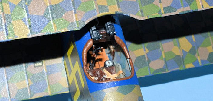 he coaming. The
machine guns are added next. The kit contains all plastic guns or there is a
“high detail” option which involves photo etch gun barrels and sights. I used
neither, opting instead to use Master barrels and details that I purchased from
Ultracast of Canada.
he coaming. The
machine guns are added next. The kit contains all plastic guns or there is a
“high detail” option which involves photo etch gun barrels and sights. I used
neither, opting instead to use Master barrels and details that I purchased from
Ultracast of Canada.
My next step was to assemble the wings and axle wing. There are top and bottom halves to all and once glued together some putty and sanding was needed to get a good result. The axle wing requires some trimming for three of the versions, with the axle sandwiched between top and bottom halves. The axle wing struts are individually added, taking care to get the alignment right. The wheels are added after painting and assembly, the exterior wheel cover added after the wheels are attached to the axle. This allows you to obtain a clean painted edge between the tires and cover. The bottom wing was painted, decaled and attached to the fuselage. Following this the tailplane, elevator, fin and rudder were all attached. Control horns were also attached to the elevator and rudder. I drilled small holes in the control horns with an 80 bit prior to attaching the rigging. The tailplane struts and lifting handles were added, but I waited until the end to attach the tail skid.
At this stage I had to a take a break in modeling to have my right knee replaced. Just prior to that we also had our upstairs carpet replaced. I moved my model, supplies and a bunch of other junk to a small bathroom in the back corner of our house, thinking it would be safe from the carpet guys. Once my knee had healed up enough, I went to move things back in place and start again on my model. To my surprise (and horror), I found only half of the bottom wing sitting on top of the open kit box. I looked around and discovered the rest of the model lying in the trash can with much of it severely damaged. The tail section was separated, the rigging torn, much of the cockpit interior damaged with parts of the machine guns bent and the Spandau mounts destroyed. There was a jagged hole in the fuselage where the left half of the lower wing had been sheared off, and there were bits of decals torn in places. My first reaction was to just throw it all away and start over with a new kit. Going after the carpet installers was not really an option (not to mention the language barrier). I showed it to my wife and told her of my plan to just junk it. She said “Absolutely not. You can fix that. Don’t give up yet!” So with that bit of encouragement, once I got over the shock of it all, I set out to see if I could salvage this model. I tried restoring everything like it was, but soon decided that the gun mounts were a lost cause, so I just left them off. It actually made the instrument panel more visible so I decided to go with that. The tail section went back together without too much trouble. None of the parts were broken, they were just separated. The biggest issue was reattaching the broken wing and restoring the bottom of the fuselage. I made a new wing spar out of Evergreen plastic card and glued the wing in place in the fuselage underside. I then glued the broken fuselage bottom back to the rest of the fuselage and patched the damage with some CA and putty. I then repainted and re-decaled where needed and I was ready to pick up where I had left off. Not sure how things would ultimately turn out I resumed building where I had stopped a few weeks earlier.
Now, where were we? Oh yes. Prior to attaching the top wing, I added the engine, radiator and nose panel, windshield, and photoetch flash guards. The cabane struts fit through the engine panels so you will need to decide what panels you want to use beforehand, as there are several to pick from depending on which airplane you build. If you want to reveal more of the engine you can leave off some or all the panels. The cabane struts on each side consist of a three-pronged part and a single strut. I chose to attach the left side engine panel for my aircraft, but I left off the right side and the top panels on each side. I then attached the cabane struts and let them set up before attaching the top wing.
 The instructions call for adding the N struts next before attaching the
top wing; however, I normally add the top wing before installing any interplane
struts. I attached the wing to the cabane struts and let it set up a while,
making sure that it stayed level while the glue dried. Then I attached each N
strut to the bottom and top wing, where they fit perfectly. To make sure the
wings set in the correct position, I then placed the aircraft nose down in the
bottom half of the kit box with the front wing edges resting on the box sides.
There is a segment in the WNW “Hints and Tips” section on their website
explaining how to do this. It’s makes for a simple wing alignment jig and seems
to work effectively.
The instructions call for adding the N struts next before attaching the
top wing; however, I normally add the top wing before installing any interplane
struts. I attached the wing to the cabane struts and let it set up a while,
making sure that it stayed level while the glue dried. Then I attached each N
strut to the bottom and top wing, where they fit perfectly. To make sure the
wings set in the correct position, I then placed the aircraft nose down in the
bottom half of the kit box with the front wing edges resting on the box sides.
There is a segment in the WNW “Hints and Tips” section on their website
explaining how to do this. It’s makes for a simple wing alignment jig and seems
to work effectively.
I added the rigging to the underside of the top wing using steel wire and threaded it through the small holes in the fuselage. I made no attempt to attach the wires to the end of the rudder pedal column inside the fuselage. I added the ailerons, with control horns attached, to the top wing, then added rigging to each aileron using EZ Line. I also added rigging to the tail section, attaching rigging from the various control horns to the fuselage and from the fin to the stabilizer. As WWI aircraft go, rigging the DVII is a piece of cake.
The completed undercarriage is attached to the fuselage very much like the real thing was. The front undercarriage struts fit into a small opening in the fuselage frame and the rear struts attach to the fuselage bottom next to the lower wing. I’ve had some issues in the past with Wingnut kits having undercarriages that were a bit wobbly, but I had no such issues with this kit. I suspect it has something to do with the builder being more careful during assembly. Rigging was added to the undercarriage assembly using EZ Line.
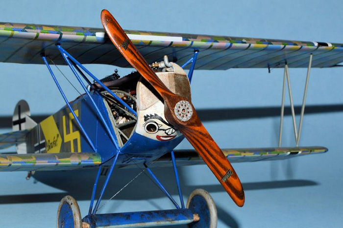
I finished construction by adding the tail skid and the propeller. The propeller is a hand carved one from LF Productions and has the Heine decal already on it. It looks a little thick to me, but I do like how the wood laminations show. I decided not to glue it so it could be removed as needed.
| COLORS & MARKINGS |
I began by painting the fuselage interior with Model Master Acrylic RLM Gray to lay a foundation prior to adding the interior lozenge decals. Once the paint was dry I gave it a shot of Future, then added the decals. The floorboard was painted a wood grain finish of MM Tan, glazed with Griffin’s Burnt Umber for the wood grain. The control stick was painted black, and rudder pedals were painted RLM Gray as was the seat. The seat cushion was painted MM Leather and glazed with a bit of Burnt Umber. The throttle control lever was also painted wood grain. The rear screen behind the seat was covered in lozenge decal. The HGW seat belts were given a thin wash of dirty thinner to give them a little color.
The interior fuselage framing was painted RLM Gray, and various control parts were painted black, including the compass. The instrument panel was painted in a wood grain and the instrument dials were painted black. The decals for the instrument dials were added and a drop of clear parts cement was added to simulate glass covers.
The ammo boxes were painted aluminum, and the fuel tank was painted RLM Gray. The fuel tank spigots were painted Polly Scale Copper, which looks like brass. The hand pump for pressurizing the fuel tank was also painted Brass. The machine guns were painted MM Gun Metal and drybrushed with a bit of Steel. The engine firewall was painted aluminum then weathered with a wash of the Griffin’s Burnt Umber.
 The engine crankcase was painted Aluminum and the cylinders were painted
MM Gun Metal. A few decals are applied to the crankcase and cylinders. The
rocker box assembly was painted Steel then highlighted with some MM Jet Exhaust.
The tubes for spark plug wires were painted Rust, the magnetos Gun Metal, as
were the intake manifolds. This was all drybrushed with a bit of Steel. The air
pump was painted Aluminum and Brass, and small bits here and there were also
picked out in Brass. The exhaust pipes were painted Jet Exhaust, then drybrushed
with some Rust and Dark Gray. Finally, the engine was given a wash of thinned
Burnt Umber for oil and grime.
The engine crankcase was painted Aluminum and the cylinders were painted
MM Gun Metal. A few decals are applied to the crankcase and cylinders. The
rocker box assembly was painted Steel then highlighted with some MM Jet Exhaust.
The tubes for spark plug wires were painted Rust, the magnetos Gun Metal, as
were the intake manifolds. This was all drybrushed with a bit of Steel. The air
pump was painted Aluminum and Brass, and small bits here and there were also
picked out in Brass. The exhaust pipes were painted Jet Exhaust, then drybrushed
with some Rust and Dark Gray. Finally, the engine was given a wash of thinned
Burnt Umber for oil and grime.
The fuselage, wings and tailplane were first painted RLM Gray where the lozenge decals would go, and MM Dark Blue for the front section of the fuselage. Then they were given several shots of Future to prepare the surface. Once dry and glossy, the lozenge decals were added to the fuselage and wings. The wings were covered in five color lozenge while the fuselage and tail were covered with four color. This was not that unusual a practice and it is always important to carefully check references prior to applying lozenge camo. The wing lozenge already has the rib tapes on it so that saves much time and trouble. I had to trim the lozenge fuselage side panels a bit to conform to this aircraft’s color scheme, but the underside fit perfectly. I used small amounts of MicroScale and Set in places to make the decals conform to the surface.
Once the lozenge was dry I then set out to paint a brown glaze over the upper surface lozenge on the fuselage, tail, and wings. This was a common practice, especially with DVIIs, to tone down the bright colors of the lozenge camouflage. If you ever go to the National Air and Space Museum you will notice that the Fokker DVII’s lozenge is very muted compared to the Albatros DV, which has not been overpainted with the brown glaze. For the model, the brown glaze is made from a mixture of 1 part Tamiya Flat Earth with 10 parts clear gloss, then carefully and lightly sprayed with an airbrush until the desired result is achieved. The goal is to tone down the colors but still see the various “lozenges” in the camouflage. It’s better to build up the color slowly because once it’s overdone it’s almost impossible to remove it without damaging the decals underneath.
 Once the glaze was done I then applied a coat of Future to prepare for
the next set of decals. The “Bowke” decal on the fuselage is one long decal
containing the cross all the way to the swastika. There are several small
lettering decals in various places including the struts and tailplane. The N
struts and tail struts were painted RLM Gray. The cabanes were painted Dark
Blue. The rudder and fin were painted White, and crosses were applied to both
sides. The radiator/nose section is painted White and a comical facial decal is
applied to highlight the extra holes drilled into the lower nose cowling to aid
in cooling. The radiator is painted with Steel and weathered a bit with Burnt
Umber. The left side engine panel is painted Dark Blue with a small part of the
front section painted White to match the white of the radiator cowling.
Once the glaze was done I then applied a coat of Future to prepare for
the next set of decals. The “Bowke” decal on the fuselage is one long decal
containing the cross all the way to the swastika. There are several small
lettering decals in various places including the struts and tailplane. The N
struts and tail struts were painted RLM Gray. The cabanes were painted Dark
Blue. The rudder and fin were painted White, and crosses were applied to both
sides. The radiator/nose section is painted White and a comical facial decal is
applied to highlight the extra holes drilled into the lower nose cowling to aid
in cooling. The radiator is painted with Steel and weathered a bit with Burnt
Umber. The left side engine panel is painted Dark Blue with a small part of the
front section painted White to match the white of the radiator cowling.
The upper and lower wing crosses were applied as well as a white decal strip applied to the leading edge of the top wing. This represents a strip of luminous radium applied to make the aircraft more visible in the dark. The undercarriage was painted the same dark blue as the fuselage and cabane struts. The bungee cords around the axle were painted Gunze Sail Color and then weathered with Burnt Umber. The tires were painted MM Neutral Gray, drybrushed with some Tamiya Earth, and given a wash of Burnt Umber. The tailskid was finished in a wood grain using MM Tan and Griffins’ Burnt Umber. The whole model was given a light coat of MM Satin to tone down some of the glossiness.
| CONCLUSIONS |
After several weeks, a pause for new carpet (and a new knee), a few more weeks for damage repair and resumption of construction, the Fokker DVII was finally finished. Despite the damage I’m overall pleased with the result. It makes a fine addition to my model collection…if I could just find a place to put it!
| REFERENCES |
Building the Wingnut Wings Fokker DVII, Albatros Productions, Ray Rimell, 2014.
Wingnut Wings kit instructions.
Swastika, Wikipedia.
24 May 2018
Copyright ModelingMadness.com
If you would like your product reviewed fairly and fairly quickly, please contact the editor or see other details in the Note to Contributors.
Back to the Main Page Back to the Review Index Page Back to the Previews Index Page