
| KIT #: | |
| PRICE: | |
| DECALS: | |
| REVIEWER: | Stephen Foster |
| NOTES: | Kit Bashed |
| HISTORY |
The Fokker DVI was a derivative of the Fokker Dr I triplane yet it also had some
features in common with the more famous DVII: the fuselage and tail were
basically Dr I components while the wings were
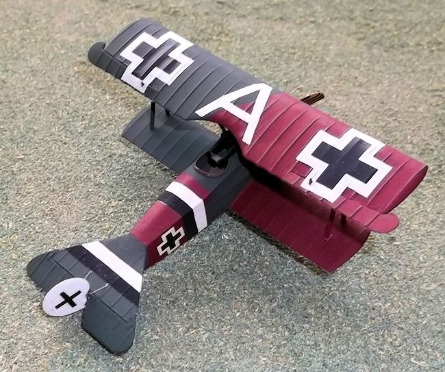 similar to the DVII except that
they had a lower aspect ratio. The machines were to have been powered by 145 hp
or 160 hp rotary engines but neither power plant was ready so production models
were fitted with copies of 110 hp French Le Rhones. They were armed with two
Spandau 0.303 inch machine guns mounted in front of the pilot. The prototype
aircraft took part in the Aldershof fighter trials in January and February 1918,
following which an order for approximately 60 machines was placed. Only a small
number of them saw front line service with Jasta 84 and other units and these
were quickly replaced by DVII's and relegated to training duties. The DVI was a
very manoeuvrable machine which could hold its own against contemporary Allied
types, but the German Air Force had decided to standardise on the DVII and so
the potential of the DVI was never fully realised.
similar to the DVII except that
they had a lower aspect ratio. The machines were to have been powered by 145 hp
or 160 hp rotary engines but neither power plant was ready so production models
were fitted with copies of 110 hp French Le Rhones. They were armed with two
Spandau 0.303 inch machine guns mounted in front of the pilot. The prototype
aircraft took part in the Aldershof fighter trials in January and February 1918,
following which an order for approximately 60 machines was placed. Only a small
number of them saw front line service with Jasta 84 and other units and these
were quickly replaced by DVII's and relegated to training duties. The DVI was a
very manoeuvrable machine which could hold its own against contemporary Allied
types, but the German Air Force had decided to standardise on the DVII and so
the potential of the DVI was never fully realised.
| THE KIT |
 Magazine in July 1972,
but as this is long out of print and hard to come by I am providing some notes
based on his original article and my own model. Mine was made over 35 years ago
and followed Wollett's method, but I used the Revell Dr I and Fokker DVII rather
than the Airfix Dr I. Today there are a number of Dr I and DVII kits to choose
from as a basis for this project - it really depends upon how much you wish to
spend. If you decide to use a Roden DVII choose an early variant as the basis
for your model. This description is based on the two Revell kits as already
explained but the procedures should be easily adaptable to other kits.
Magazine in July 1972,
but as this is long out of print and hard to come by I am providing some notes
based on his original article and my own model. Mine was made over 35 years ago
and followed Wollett's method, but I used the Revell Dr I and Fokker DVII rather
than the Airfix Dr I. Today there are a number of Dr I and DVII kits to choose
from as a basis for this project - it really depends upon how much you wish to
spend. If you decide to use a Roden DVII choose an early variant as the basis
for your model. This description is based on the two Revell kits as already
explained but the procedures should be easily adaptable to other kits.
| CONSTRUCTION |
 have
the span reduced by cutting out the centre portion - this should be 1 and 1/16
inches long. This will leave two separate wing halves and these should be filed
so that they butt against the fuselage sides.
have
the span reduced by cutting out the centre portion - this should be 1 and 1/16
inches long. This will leave two separate wing halves and these should be filed
so that they butt against the fuselage sides.
The fuselage
needs to be lengthened so start by cutting off the rudder and setting it aside
for use later. Now add any cockpit detail that you wish - a seat, rudder bar,
control column, stringers on the fuselage sides and a bar in front of the
pilot's seat are recommended. Instruments were clamped to the bar and to the
fuselage stringers and were probably similar to the Dr I. I make my instruments
by slicing pieces of plastic rod or stretched sprue which I paint black. When
you have assembled the fuselage halves cut out the centre section of the middle
wing of the triplane and glue this to the top of the fuselage. Cut a disc of 60
thou card and cement this to the front of the fuselage, and using the fuselage
as a plan cut a piece of 40 thou card to fit underneath but make it 3/16 inch
longer so that it will extend to the new fuselage length.
 When you glue this to
the fuselage bottom you will also need to fill the cut-out where the lower wing
would have been fitted. Add plastic card to the sides of the rear fuselage above
the new bottom. On the top of the fuselage add a piece of 30 thou card to the
front end of the tailplane cut-out - this should be 3/16 inch wide. Fill any
gaps between the card and the fuselage and when both the filler and cement are
dry reshape the rear. Fill the holes for the machine guns and struts on the
forward part of the fuselage and glue the engine and cowling of the DrI to the
new front.
When you glue this to
the fuselage bottom you will also need to fill the cut-out where the lower wing
would have been fitted. Add plastic card to the sides of the rear fuselage above
the new bottom. On the top of the fuselage add a piece of 30 thou card to the
front end of the tailplane cut-out - this should be 3/16 inch wide. Fill any
gaps between the card and the fuselage and when both the filler and cement are
dry reshape the rear. Fill the holes for the machine guns and struts on the
forward part of the fuselage and glue the engine and cowling of the DrI to the
new front.
| COLORS & MARKINGS |
| FINAL CONSTRUCTION |
 piece of Contrail strut or Evergreen
strip. If you use the latter material shape it to aerofoil section before you
glue it into place. Cut four small holes in the fuselage to take the
undercarriage legs. Use the stub-wing axle and undercarriage struts from the Dr
I and glue the legs to the axle with the longer legs in front. When this is
drying and still flexible place the ends of the legs in the holes in the
fuselage and glue into place. Allow to dry out thoroughly. The final details can
now be added: propellor, rudder, wheels, tail skid, control horns to the control
surfaces, and struts under the tailplane. You will also need to add two small
handles under the rear fuselage and a step under the cockpit on the port (left)
side of the fuselage. The only rigging on this model are the control cables from
the control horns around the tail to the fuselage, from the ailerons to the
wings, from the fuselage to the top wing and the bracing between the two front
undercarriage legs.
piece of Contrail strut or Evergreen
strip. If you use the latter material shape it to aerofoil section before you
glue it into place. Cut four small holes in the fuselage to take the
undercarriage legs. Use the stub-wing axle and undercarriage struts from the Dr
I and glue the legs to the axle with the longer legs in front. When this is
drying and still flexible place the ends of the legs in the holes in the
fuselage and glue into place. Allow to dry out thoroughly. The final details can
now be added: propellor, rudder, wheels, tail skid, control horns to the control
surfaces, and struts under the tailplane. You will also need to add two small
handles under the rear fuselage and a step under the cockpit on the port (left)
side of the fuselage. The only rigging on this model are the control cables from
the control horns around the tail to the fuselage, from the ailerons to the
wings, from the fuselage to the top wing and the bracing between the two front
undercarriage legs.
| CONCLUSIONS |
January 2014
If you would like your product reviewed fairly and quickly, please contact the editor or see other details in the Note to Contributors.