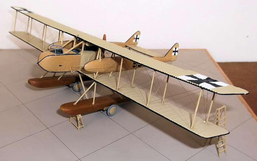
1/72 AGO C.II
| KIT #: | |
| PRICE: | |
| DECALS: | Home made with printer |
| REVIEWER: | Stephen Foster |
| NOTES: | Scratch built |
| HISTORY |
The Ago Fluggesellschaft
Gmbh of Johannisthal was established in 1912 as the Berlin branch of the
Flugzeugwerke Gustav Otto. Otto was a Bavarian engineer and early
pioneer of flight and developed a series of very similar designs known
collectively as Doppeldekkers. Unfortunately for Otto the Prussian air
service would not accept the Doppeldekker design for military service as
it was considered to be structurally too weak, so although some machines
did serve with Bavarian air units, the military market was limited.
(Some modellers and other authors have given the designation CI to the
Doppeldekker. This is incorrect as these machines were never fitted with
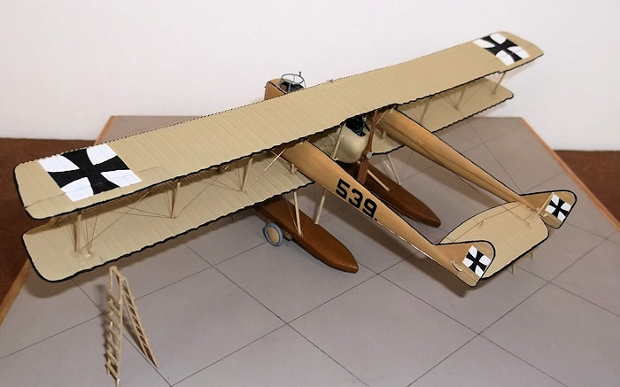
a permanent armament). In early 1915 Otto produced a new design based on
a pusher layout with a central nacelle as on the Doppeldekker, but with
twin booms instead of an open tail. This left the observer with a wide
field of fire if armed with a machine gun on a flexible mounting. The
booms were made from two moulded plywood shells joined at the centre,
giving a much stronger airframe. Both the army and the navy ordered land
planes in early 1915, and the first CI
 airframe was delivered to the
Army in April of that year. This aircraft became the first machine to
receive the C designation, meaning that it was the first armed
two-seater, being equipped with a Parabellum machine gun on a ring
mounting in the front cockpit. Production machines followed but because
Ago was a relatively small company the total number of CI machines
produced was probably only around 64. Nevertheless it was a type that
proved to be robust and had a long active service on both the western
and eastern fronts, the last machines being recorded in service with
front line units in April in 1917 thereafter they were used by training
units. It was popular with crews as it was relatively easy to fly and
could withstand damage and still return to an airfield. The Ago types
were initially reported as twin engined and more heavily armed than they
actually were, but even when they were recognised as single engined
pushers, they were treated with respect by Allied pilots. It was only
later in their service when tractor fighters were introduced that the
inherent weaknesses of the pusher layout became important and the type
had to be withdrawn from front line service.
airframe was delivered to the
Army in April of that year. This aircraft became the first machine to
receive the C designation, meaning that it was the first armed
two-seater, being equipped with a Parabellum machine gun on a ring
mounting in the front cockpit. Production machines followed but because
Ago was a relatively small company the total number of CI machines
produced was probably only around 64. Nevertheless it was a type that
proved to be robust and had a long active service on both the western
and eastern fronts, the last machines being recorded in service with
front line units in April in 1917 thereafter they were used by training
units. It was popular with crews as it was relatively easy to fly and
could withstand damage and still return to an airfield. The Ago types
were initially reported as twin engined and more heavily armed than they
actually were, but even when they were recognised as single engined
pushers, they were treated with respect by Allied pilots. It was only
later in their service when tractor fighters were introduced that the
inherent weaknesses of the pusher layout became important and the type
had to be withdrawn from front line service.
The German navy showed an
interest in the type from the start and ordered land plane variants in
early 1915. In May 1915 the first floatplane was delivered to the navy
where it was used for training in bombing and machine gunnery. The CI
types were usually powered by either 150hp Benz Bz III and later 160hp
 Merceedes DIII engines; early machines had radiators mounted on the
nacelle sides, but later the radiators were joined and moved under the
top wing. In late 1915 the CI was replaced by the CII with the more
powerful Benz Bz IV engine. Some CII machines had an extended wingspan
with a third bay added. The navy accepted several of the extended wing
CII's which were fitted with floats and these were used for maritime
reconnaissance and bombing, and later training. These seem to have been
in service for most of 1916 and may not have been withdrawn from front
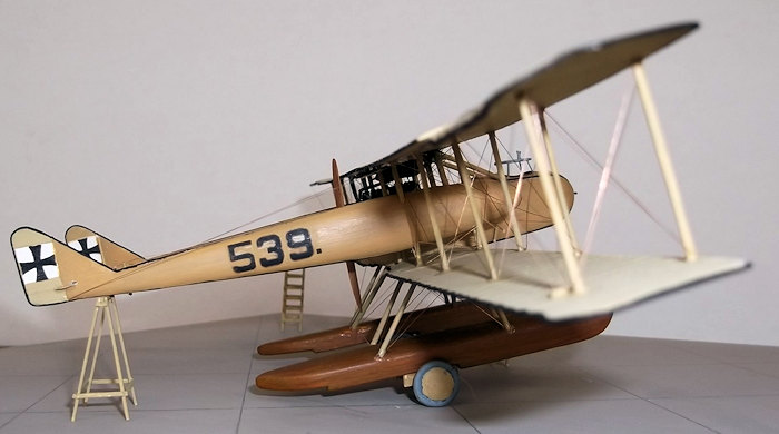
line service until 1917. The aircraft depicted in the model is of 539
which was photographed at an unidentified naval station, probably in
1916. This machine was powered by a Benz B IV engine and had the gravity
tank mounted on the starboard side away from the exhaust manifolds. Agos
were delivered and flown painted in a brown dope with the wood booms
either left in wood or painted to match the linen.
Merceedes DIII engines; early machines had radiators mounted on the
nacelle sides, but later the radiators were joined and moved under the
top wing. In late 1915 the CI was replaced by the CII with the more
powerful Benz Bz IV engine. Some CII machines had an extended wingspan
with a third bay added. The navy accepted several of the extended wing
CII's which were fitted with floats and these were used for maritime
reconnaissance and bombing, and later training. These seem to have been
in service for most of 1916 and may not have been withdrawn from front
line service until 1917. The aircraft depicted in the model is of 539
which was photographed at an unidentified naval station, probably in
1916. This machine was powered by a Benz B IV engine and had the gravity
tank mounted on the starboard side away from the exhaust manifolds. Agos
were delivered and flown painted in a brown dope with the wood booms
either left in wood or painted to match the linen.
| CONSTRUCTION |
I started by constructing the booms. The profile of the booms was traced from the plan on to 30 thou card and two sections per boom cut out. then two other sections were cut from 20 thou card and a laminate made of two x 30 and one 20thou card. This was compressed with a pile of books while the glue dried, and then the booms were shaped with glass paper until the correct profiles were achieved. The fins and rudders were cut from 20 thou card and glued into place when the booms were ready.
The nacelle was made from
a push mould - a male mould was carved from balsa and a female was cut
in a sheet of plywood. 30 thou card was pinned over the hole in the
plywood and the male mould used to make two halves of the fuselage
nacelle. The halves could then be cut from the plastic sheet and the
edges sanded and smoothed until the correct size was made. The cockpit
and engine holes were cut out and filed smooth. The interior of the
cockpits was constructed from plastic rod and card and consisted of a
simple framework for the nacelle, seats, floors, control column and
rudder bar and two thicker pieces of rod behind the pilot to represent
bomb chutes. The interior of the cockpit was painted wood for the
floors, brown for the seats and natural linen for the sides. The frame
was painted black as this was steel tube not
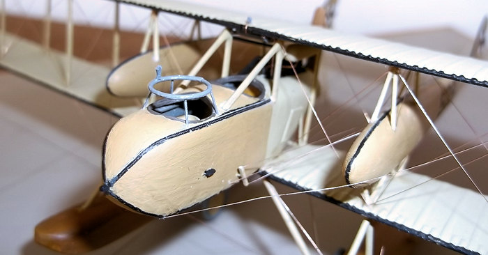
 wood. A small aperture was
cut out under the nose to represent the pilot's window, the glass being
represented by a small piece of acetate cut from a bubble pack. When the
cockpit was ready the floor was cemented to one nacelle half and the
other joined. The corners of the moulding were rounded but one of the
distinctive features of the Ago was the square section of the nose and
bottom of the nacelle. To get rid of the rounded corners I cemented thin
strips of heat stretched sprue along the rounded edges and when this was
dry filled the gaps between the sprue and side with filler. When this
was rubbed down neat square edges were made. Various holes were drilled
into the nacelle to take struts later, the propellor shaft and the rear
spar at the back of the nacelle.
wood. A small aperture was
cut out under the nose to represent the pilot's window, the glass being
represented by a small piece of acetate cut from a bubble pack. When the
cockpit was ready the floor was cemented to one nacelle half and the
other joined. The corners of the moulding were rounded but one of the
distinctive features of the Ago was the square section of the nose and
bottom of the nacelle. To get rid of the rounded corners I cemented thin
strips of heat stretched sprue along the rounded edges and when this was
dry filled the gaps between the sprue and side with filler. When this
was rubbed down neat square edges were made. Various holes were drilled
into the nacelle to take struts later, the propellor shaft and the rear
spar at the back of the nacelle.
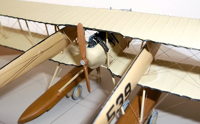
The engine was made from laminated plastic card for the engine block, rod for the cylinders and thinner rod for the exhausts. The carburettor and inlet pipes were also made from card and rod. The engine block was painted aluminium (silver with a dash of medium grey added), the cylinders and exhausts were black. When the engine was complete it was placed carefully into the fuselage nacelle and glued to a small shelf which had been put in earlier for the purpose.
The tail surfaces were
made from 20 thou card cut to shape with ribs added to the horizontal
surface as per the wings. The wings were cut from 30 thou card which had
been bent by placing a sheet of card into a waste pipe which was sealed
at one end. Near boiling water was poured into the tube and then emptied
after 10-15 seconds. When the wing blanks had been cut and sanded to an
aerofoil section, the rib spacings were marked with a fine pencil using
the plan as a guide, and strips of 10 x 20 thou card glued on to the
upper surfaces. These were then sanded down until only slight ridges
remained, and these were sealed with white paint. The riblets on the
leading edges of the wings were cut from stretched sprue and they too
were then sanded and painted. The ailerons were cut out of the top wing
and the trailing edge droop added by cementing a short piece of 10 x 20
thou card on the trailing edge and when dry sanding the upper surface
and adding filler around the edges of the card and shaping the lower
surface. The ailerons were then cemented to the wing at slight angles to
give a more realistic look to the finished model. Holes were drilled for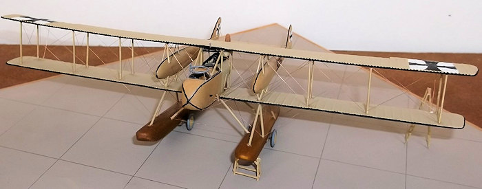 the strut location points in the top wing and for the struts and float
struts in the lower wing. The struts were cut from 20 x 30 thou strip
and shaped to aerofoil section. The cabane struts were cut in one piece
from 30 thou card and sanded to shape. A gravity fuel tank was shaped
from a piece of sprue and two holes drilled, one at each end, to take
the sprue pins which would attach it to the struts later.
the strut location points in the top wing and for the struts and float
struts in the lower wing. The struts were cut from 20 x 30 thou strip
and shaped to aerofoil section. The cabane struts were cut in one piece
from 30 thou card and sanded to shape. A gravity fuel tank was shaped
from a piece of sprue and two holes drilled, one at each end, to take
the sprue pins which would attach it to the struts later.
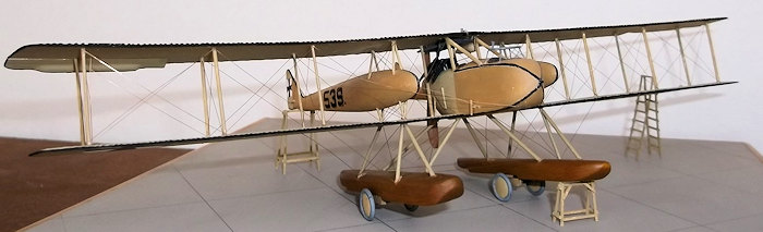
The floats were made from 30 thou card for the top with a series of supports along the floats so that a support formed the rear edge of the steps. The sides were shaped from 20 thou card which was glued to the top of the float and the interior supports. When this was dry the front and rear ends were gently curved and cemented in place, followed by the bottoms which were in three sections and from 10 thou card scored to represent the keels. A little filler had to be added to some of the joins and the whole sealed with paint. These were then given a coat of Revell acrylic Ockre (88) as primer and then painted in oils: I used a mix of burnt sienna and raw sienna in a ratio of approximately 2:1. The oil paints took three days to dry in my airing cupboard because we had some dull cool days at the time. I then coated the floats with Revell clear orange acrylic varnish (730) - I applied 6 coats before I had a nice smooth finish. Finally the strut holes were drilled in the floats, and struts cut from 40 thou rod. These are slightly over scale in thickness but strength has to be considered here. I could have used brass rod but that would have presented other problems.
Assembly began by attaching the lower wings to the fuselage. This joint is small and consequently potentially weak, but I strengthened it by drilling two small holes in the inner edges of the wings and one in the lower rear of the fuselage nacelle. I then inserted a steel pin through the nacelle and into each lower wing. This requires very careful measurement and drilling but it was successful and undoubtedly helps to strengthen the joint. The wing to fuselage struts were glued into place and the model was ready for the main painting stage.
| COLORS & MARKINGS |
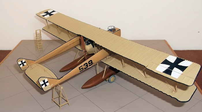
 The basic colour was a mix
of approximately 3 parts Humbrol clear doped linen (HB 103) and 2 parts
natural wood (HB 94). The front of the nacelle and booms were Revel
acrylic Ockre (88). The struts were all painted in the same basic colour
mix with a little extra natural wood added, as was the rear of the
fuselage nacelle - all of these were painted metal on the real aircraft.
The black lining on the booms and flying surfaces were painted with a
fine paintbrush and steady hand! The crosses were printed on my home
computer, as was the serial on the sides of the booms. These were
applied at this stage.
The basic colour was a mix
of approximately 3 parts Humbrol clear doped linen (HB 103) and 2 parts
natural wood (HB 94). The front of the nacelle and booms were Revel
acrylic Ockre (88). The struts were all painted in the same basic colour
mix with a little extra natural wood added, as was the rear of the
fuselage nacelle - all of these were painted metal on the real aircraft.
The black lining on the booms and flying surfaces were painted with a
fine paintbrush and steady hand! The crosses were printed on my home
computer, as was the serial on the sides of the booms. These were
applied at this stage.
| FINAL CONSTRUCTION |
With the painting finished
it was time to make the underwing radiator and associated plumbing. The
radiator was made from two lengths of rod for the sides and short pieces
of 20 thou card for the cooling vanes. Rod also provided the material
for the pipes from the header tank in the top wing and from the rear of
the port (left) pipe to the engine compartment. These parts were
assembled and painted dark grey before the radiator was attached to the
underside of the top wing. Now the outboard wing struts were cemented to
the lower wing, as were the forward and rear cabane struts on the
fuselage. Small drops of glue were placed into the strut holes on the
upper wing and the latter was gently lowered on to the struts: all of
this was carried out as one operation to allow fine adjustment of the
struts into the holes in the upper wing. The wing was then weighted with
small weights, (pots of paint in my case), and allowed to dry out
overnight. This structure is strong enough to allow the remaining struts
to be inserted carefully the next day. I have used this method of
construction on all of my pusher models (I have 7 others), and it allows
correct
 alignment to be achieved while not trying to do too much at once
and running into problems. With the wing struts in place it was time to
complete the plumbing of the radiator with the pre-cut and painted
pipes.
alignment to be achieved while not trying to do too much at once
and running into problems. With the wing struts in place it was time to
complete the plumbing of the radiator with the pre-cut and painted
pipes.
Now for the booms. This
requires more care than ever if the model is to be a success: I drilled
the holes in the booms for the struts and cut and fitted the latter
before attempting to fix the booms to the wings. Very careful
measurement is needed here to get position and alignment correct. I also
drilled two very small holes in the insides of the booms and the
horizontal tail surface so that I could insert short pieces of thin
stretched sprue to act as pins to strengthen what would otherwise be a
very weak joint. (I was glad that I did because later I had a mishap and
one of the booms twisted out of alignments and had to be re-attached to
the wing: the tail surface joint also had to be repaired and the pins
were helpful in bringing this section back into its correct location.
Scratch-building comes with its problems just like any other form of
modelling, no matter what the finished product may look like). I joined
the booms to the horizontal tail surface first, and while this was still
drying inserted the booms into the spaces between the wings. I had
placed drops of glue into the holes in the wings, so the boom struts
were able to drop into these holes and were held straight away. The rear
of the booms were held up by plastic card piles and the sides were
supported with paint tins again - the whole was a bit of a Heath
Robinson jig but I had practised beforehand to work out exactly what was
required and had everything ready: it took half an hour to prepare the
assembly and five minutes to complete it. Planning is always worth
while. I left the whole structure to dry out over night before I
attempted to handle it again. Now the floats could be fitted. Careful
measurements were made using a pair of dividers for the lengths of rod
required. These were then cut and inserted into the holes which had been
drilled in the tops of the floats
 and allowed to dry. Then one float at
a time was fixed to the underside of the wings and fuselage and allowed
to dry out completely. The struts were painted after the floats were in
position. Final details including the control horns on the fuselage and
tail and step on the fuselage side were added before the rigging
started.
and allowed to dry. Then one float at
a time was fixed to the underside of the wings and fuselage and allowed
to dry out completely. The struts were painted after the floats were in
position. Final details including the control horns on the fuselage and
tail and step on the fuselage side were added before the rigging
started.
I rig my models with 40 SWG copper wire which is rolled straight with a piece of brass strip on a wooden block and attached with superglue. I measure each length from the model using a pair of dividers and start with the short sections between the boom struts as these are the least accessible. These were followed by the rear of the wings and between the front and rear pairs of struts. The control cables on the insides of the booms were next, followed by the tail surfaces and supports. The the control wires from the booms to tail were fitted, followed by the front of the wings except for the inner bay between the booms and nacelle. Here the control wires were fixed before the bracing wires. Finally the floats were rigged followed by the anti- drag wires at the front and rear. To finish the model I added the raised gun ring over the observer's cockpit and a propellor which I had carved from a piece of strip wood.
| CONCLUSIONS |
I have made or converted many pusher types and this one was the most difficult so far because of the boom structure. In addition I made life a bit more difficult for myself by making it a floatplane - a simple V undercarriage would have been easier. Making the parts was no more difficult than making parts for super-detailing or conversions and would be well within the capabilities of an experienced modeller. Careful and repeated measurement, and careful thought and pre-planning meant that no problem was insuperable and the whole model went together remarkably well in the end. This aircraft is available as a vacuform but the assembly would not be any easier - patience and care will still be needed for a successful model to result. However I now have a German single engined pusher in my collection and a type which is little known and rarely seen in model shows, so it was well worth the effort.
| REFERENCES |
The best source of information and plans for this machine is the DataFile number 75. This is for the CI variants - the CII extended wing was exactly 60 feet which in scale means 10 inches so it is easy to enlarge. The lower wing span is increased by the same amount as the upper wing - all the other dimensions remained the same. I estimated the float dimensions from a drawing and from an excellent photo of 539, both of which I found on the net. K. Munson's Bombers 1914-1919 in the Blandford colour series also provided some background information. There are various pieces of information scattered around a number of websites, one of the more useful being flyingmachines.ru but it is relatively easy to find information on this type.
6 June 2016
C
opyright ModelingMadness.comIf you would like your product reviewed fairly and fairly quickly, please contact the editor or see other details in the Note to Contributors.