Wingnut Wings 1/32 Halberstadt CL.II
| KIT #: | 32062 |
| PRICE: | $129.00 SRP |
| DECALS: | Five options |
| REVIEWER: | Otis Goodin |
| NOTES: | Great kit as usual. Find one and build it. |
| HISTORY |
Halberstadter Flugzeugwerke, aka Halberstadt, was a German aircraft manufacturer founded in 1912 in the town of Halberstadt in the Province of Saxony. Its original name was Deutsche Bristol Werke Flugzeug-Gesellschaft mbH, and it was a joint venture with the British and Colonial Aeroplane Company, Ltd. In 1913 the name was changed to Halberstadt. The joint venture terminated with the outbreak of WWI, and Halberstadt began producing aircraft for the German Idfleig. The company built more than 1,700 reconnaissance aircraft (C type), and 85 fighter planes (D type). After the war, because of restrictions of the Treaty of Versailles, the company produced agricultural machinery and repaired railroad equipment. The company went into insolvency in 1926, and its factories were later used by Junkers beginning in 1935.
 One of Halberstadt’s most successful aircraft was the
Halberstadt Cl.II, a two-seat fighter/ground attack aircraft. The “Cl” provision
stood for two-seater light aircraft. Design of the Cl.II began in early 1917
when the Idfleig ordered the development of a smaller, lighter two-seat aircraft
to replace the older, slower C types then in use. Halberstadt based the Cl.II on
its earlier unsuccessful D.IV, a single seat fighter plane. By making the D.IV
fuselage and cockpit area longer and larger, Halberstadt ended up with a
two-seat aircraft that was faster and more agile than existing C types. These
qualities suited it for ground attack and troop support. The Cl.II featured an
all wood fuselage covered with thin plywood paneling. By placing the pilot and
observer in the same cockpit, they were able to communicate effectively in
flight. The observer manned a 7.92mm machine gun that was placed atop an
elevated gun ring that offered good visibility and field of fire, allowing it to
direct fire at targets on the ground. Production of the Cl.II began in May 1917,
and eventually 700 were built before production shifted to the improved Cl.IV in
mid-1918. The Cl.II was an effective ground support aircraft and this eventually
became its primary role. The Cl.II remained in service until the end of the war.
One of Halberstadt’s most successful aircraft was the
Halberstadt Cl.II, a two-seat fighter/ground attack aircraft. The “Cl” provision
stood for two-seater light aircraft. Design of the Cl.II began in early 1917
when the Idfleig ordered the development of a smaller, lighter two-seat aircraft
to replace the older, slower C types then in use. Halberstadt based the Cl.II on
its earlier unsuccessful D.IV, a single seat fighter plane. By making the D.IV
fuselage and cockpit area longer and larger, Halberstadt ended up with a
two-seat aircraft that was faster and more agile than existing C types. These
qualities suited it for ground attack and troop support. The Cl.II featured an
all wood fuselage covered with thin plywood paneling. By placing the pilot and
observer in the same cockpit, they were able to communicate effectively in
flight. The observer manned a 7.92mm machine gun that was placed atop an
elevated gun ring that offered good visibility and field of fire, allowing it to
direct fire at targets on the ground. Production of the Cl.II began in May 1917,
and eventually 700 were built before production shifted to the improved Cl.IV in
mid-1918. The Cl.II was an effective ground support aircraft and this eventually
became its primary role. The Cl.II remained in service until the end of the war.
Only one Halberstadt Cl.II survives today, a partial airframe in the Polish Aviation Museum in Krakow. There are Cl.IVs at the National Air and Space Museum and the Luftwaffen Museum in Berlin.
| THE KIT |
 Wingnut Wings released the Halberstadt Cl.II, both
early and late versions, in November 2018. The model that is the subject of this
review is the late version. The kit contains 201 plastic parts, 9 photo etched
parts, optional engines, propellers, and armament. Decals, including 5 color
lozenge and markings for the many choices are included. A 26 page glossy
instruction book, complete with archived photos of Halberstadts, is included. As
is the Wingnut tradition the modeler has a choice of building one of five
aircraft from the kit: (1) Cl.II “V” of the Royal Prussian Schusta, as it
appeared in March 1918; (2) Halberstadt CL.II “2, Brunhilde,” believed to have
been flown by Karl Prim of the Royal Bavarian Schlasta 27b, as it appeared in
mid-1918; (3) A Cl.II of the Marine Schlasta 1, as it appeared in October 1918,
and featuring the distinctive yellow markings common to Marine aircraft; (4)
Halberstadt Cl.II “Marichen” of Schlasta 15, featuring a reddish brown and green
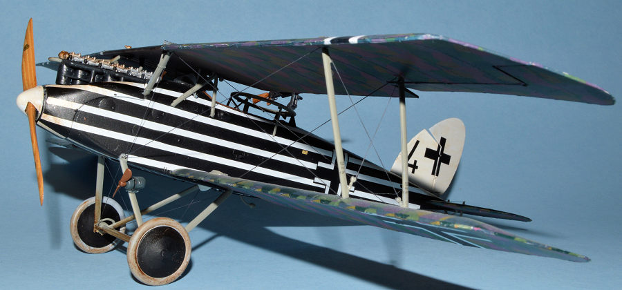
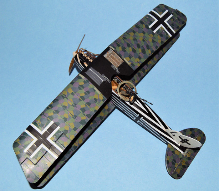
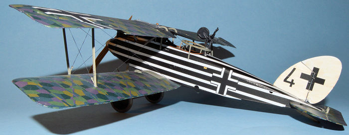
camouflage, as it appeared in mid to late 1918; and (5) the aircraft I chose to
model, a CL.II flown by Fredrich Barchert of the Royal Prussian Schlasta 21, as
it appeared in summer 1918, featuring a distinctive black and white striped
fuselage.
Wingnut Wings released the Halberstadt Cl.II, both
early and late versions, in November 2018. The model that is the subject of this
review is the late version. The kit contains 201 plastic parts, 9 photo etched
parts, optional engines, propellers, and armament. Decals, including 5 color
lozenge and markings for the many choices are included. A 26 page glossy
instruction book, complete with archived photos of Halberstadts, is included. As
is the Wingnut tradition the modeler has a choice of building one of five
aircraft from the kit: (1) Cl.II “V” of the Royal Prussian Schusta, as it
appeared in March 1918; (2) Halberstadt CL.II “2, Brunhilde,” believed to have
been flown by Karl Prim of the Royal Bavarian Schlasta 27b, as it appeared in
mid-1918; (3) A Cl.II of the Marine Schlasta 1, as it appeared in October 1918,
and featuring the distinctive yellow markings common to Marine aircraft; (4)
Halberstadt Cl.II “Marichen” of Schlasta 15, featuring a reddish brown and green
camouflage, as it appeared in mid to late 1918; and (5) the aircraft I chose to
model, a CL.II flown by Fredrich Barchert of the Royal Prussian Schlasta 21, as
it appeared in summer 1918, featuring a distinctive black and white striped
fuselage.
| CONSTRUCTION |
Work begins in the cockpit where the first order of business is to drill a hole in the floorboard for the engine sump. There are two locations to pick from, depending on if your aircraft is using the 160 hp or 180 hp engine. Following that you will place the control column support in the pilot’s section and the wireless aerial in the observer’s area. The endpiece is also added to the back end of the floorboard, and the wireless unit is added to the endpiece. Various decals are added to the wireless for dials and such. Next the rudder pedals are added, followed by the fuel tank onto which is placed the pilot’s seat. The control column and aileron control rods are then added just in front of the fuel tank and attached to the control column support unit. The engine bearers are added to the very front of the floorboard.
Various instruments are added to the fuselage framing including instrument dials, a compass, and the wireless aerial reel. Prior to attaching the framing to the floorboard, I recommend that you add any cockpit rigging, which mostly runs along the fuselage frame. I also suggest that you add the seatbelts at this point. I used HGW fabric seatbelts, but the kit provided photo etch belts would work as well provided you take the time to anneal them sufficiently to make them more malleable. Add the cockpit frames to each side of the floorboard, checking to make sure they are properly placed and fit well. Once the framing is in, add the simple instrument panel in front, and attach the hand air pump for pressurizing the fuel tank. Attach the two gun ring support pieces to the frame and the cockpit is complete.
This aircraft used the 180 hp Mercedes engine so I started construction on it. Because much of the engine is covered by cowling panels, I didn’t add any detail to the kit engine. If you decide to leave cowlings off, you might want to add some extra wiring and such to make the engine more realistic. There are plenty of references available for the Daimler Mercedes D.IIIa and III.au engine. There is a radiator pipe that attaches to the back end of the engine which is eventually attached to the radiator on the bottom side of the top wing. This pipe will most likely get knocked off during construction, so I recommend attaching it through the cowling and onto the wing when you are ready to add it to the radiator later. I even cut the bottom portion off mine since it doesn’t show anyway, and this made it easier to install. There is a decal or two added to the engine after painting that adds a realistic touch. After completing the engine, I set mine aside until I was ready to install it later.
 Following engine assembly, the next step is the
fuselage. Before painting, instructions call for you to remove a few raised
“dots” and so forth that are used on the early version kit from the interior.
Add the grease pump and the generator clutch lever to the sidewalls. Install the
magazine and empty ammo belt container to the space just in front of the cockpit
interior behind where the engine will sit. Then you are ready to join the two
fuselage halves together. There is some puttying and sanding required on the top
and bottom, but this is really it for the entire kit. I used putty, then some CA
glue a couple of times to get the gaps and lines filled. There’s also a section
of bottom to be added, along with a drain cock fairing. I did not yet add the
horizontal stabilizer because I wanted to paint the black fuselage first. At
this point I painted the fuselage with a light coat of Model Master Light Ghost
Gray flat enamel to provide a base for the black acrylic paint. Acrylic paint
does not adhere well to plastic (i.e. oil and water do not mix), so by putting a
coat of enamel as a primer over the plastic the paint peeling problem is
resolved. Since I’ve started doing this, I’ve never had a problem with the
acrylic paint peeling off. Once the enamel was dry, I then sprayed the fuselage
with Model Master Semi-Gloss Black, coated it with Future to give it a gloss
finish, and then applied the white stripe decals. (More on this in the Painting
section).
Following engine assembly, the next step is the
fuselage. Before painting, instructions call for you to remove a few raised
“dots” and so forth that are used on the early version kit from the interior.
Add the grease pump and the generator clutch lever to the sidewalls. Install the
magazine and empty ammo belt container to the space just in front of the cockpit
interior behind where the engine will sit. Then you are ready to join the two
fuselage halves together. There is some puttying and sanding required on the top
and bottom, but this is really it for the entire kit. I used putty, then some CA
glue a couple of times to get the gaps and lines filled. There’s also a section
of bottom to be added, along with a drain cock fairing. I did not yet add the
horizontal stabilizer because I wanted to paint the black fuselage first. At
this point I painted the fuselage with a light coat of Model Master Light Ghost
Gray flat enamel to provide a base for the black acrylic paint. Acrylic paint
does not adhere well to plastic (i.e. oil and water do not mix), so by putting a
coat of enamel as a primer over the plastic the paint peeling problem is
resolved. Since I’ve started doing this, I’ve never had a problem with the
acrylic paint peeling off. Once the enamel was dry, I then sprayed the fuselage
with Model Master Semi-Gloss Black, coated it with Future to give it a gloss
finish, and then applied the white stripe decals. (More on this in the Painting
section).
With the fuselage painted, it’s a good time to install the engine, the horizontal stabilizer, and the Spandau machine gun. Instead of the kit supplied gun, I used one from GasPatch and was quite pleased with it. No rolling of photo etch gun jackets was needed, and the result is much better than I can achieve on my own. Of course, it costs more, but to me, it’s worth it. After installing the machine gun on the right side of the engine (versus left on the Early version) the instructions now call for you to add the front cabane struts. These are a bit tricky and the instructions aren’t that clear. This would have been a good place for an enlarged view in the instructions. Each strut is shaped like a ‘V’ with the long end reaching up to the wing and the shorter end pointing in the direction of the engine. The ‘V’ where the two ends meet fits into a ‘V’ shaped holder on each side of the fuselage between the fuselage and the engine. Glue the ‘V’ into the holder on each side, checking each strut carefully for alignment with the other strut. Make sure the angle and the distance from the center of the fuselage is the same for each strut because these struts fit into two slots on the underside of the top wing, and their alignment is crucial to getting the top wing on straight. It wouldn’t hurt to take the center section of the top wing and use it to check the strut placement while the glue is drying.
Next add the bottom wings and the horizontal stabilizer, both of which have been covered in lozenge camouflage by this time. Next add the upper cowling section in front of the pilot’s section, taking care to drill out the required holes as called for by the version you are building. (This section has previously been painted and stripe decals applied on this version). Instructions call for the observer’s gun ring to be installed, but there is too much left to do at this point to add such a delicate piece, so I skipped this until later. Be sure to add the tachometer directly in front of the pilot and apply the decals of choice. Also add the wing compass decal and apply clear coat over the decals just added. Finally, add the windscreen with clear parts cement. I loosely covered the windscreen with some masking tape to protect it from scratches and overspray.
 The top wing is composed of three pieces: right, left,
and middle. The right and left sections are to be covered in lozenge camo, while
the middle section is painted. Once construction of the top wing is complete,
add the rear cabane struts into place. You are then ready to install the top
wing. Before doing so, insert the radiator pipe into the hole on the right side
of the front cowling so it will be in place to attach it to the underside of the
top wing once it is installed. Although the instructions call for you to add the
interplane struts to the bottom wing first, in my experience it is much easier
to add the interplane struts after the top wing has been placed atop the cabane
struts. Logic dictates that it is easier to add a wing to just four struts than
to eight or twelve struts. Turn the model over and apply a little glue into the
four locations on the center underside of the top wing. Then carefully insert
the cabane struts into the holes, inserting the rear ones first, then the front
cabanes last. Once all the struts are in place, turn the model over and let the
wing and struts set up a bit, checking the alignment to make sure the wing is on
fairly straight. Next add the interplane struts one at a time after putting a
little glue in the bottom and top locations. Once all the struts are in place,
simply hold the wings in place with a little pressure until the glue has a
chance to set up. As soon as you are comfortable that the glue has set up a
little, place the model facing downward with its wing edges on the edges of the
bottom part of the kit box. This homemade jig will allow the wings to set up
thoroughly in the correct position. Once completely dry, the wings should be
properly in line. Glue the loose radiator pipe in place, then add the radiator
water pipe from the front of the engine to its slot under the top wing. Add the
ailerons in place to the top wing, along with the aileron control rods,
completing the top wing installation.
The top wing is composed of three pieces: right, left,
and middle. The right and left sections are to be covered in lozenge camo, while
the middle section is painted. Once construction of the top wing is complete,
add the rear cabane struts into place. You are then ready to install the top
wing. Before doing so, insert the radiator pipe into the hole on the right side
of the front cowling so it will be in place to attach it to the underside of the
top wing once it is installed. Although the instructions call for you to add the
interplane struts to the bottom wing first, in my experience it is much easier
to add the interplane struts after the top wing has been placed atop the cabane
struts. Logic dictates that it is easier to add a wing to just four struts than
to eight or twelve struts. Turn the model over and apply a little glue into the
four locations on the center underside of the top wing. Then carefully insert
the cabane struts into the holes, inserting the rear ones first, then the front
cabanes last. Once all the struts are in place, turn the model over and let the
wing and struts set up a bit, checking the alignment to make sure the wing is on
fairly straight. Next add the interplane struts one at a time after putting a
little glue in the bottom and top locations. Once all the struts are in place,
simply hold the wings in place with a little pressure until the glue has a
chance to set up. As soon as you are comfortable that the glue has set up a
little, place the model facing downward with its wing edges on the edges of the
bottom part of the kit box. This homemade jig will allow the wings to set up
thoroughly in the correct position. Once completely dry, the wings should be
properly in line. Glue the loose radiator pipe in place, then add the radiator
water pipe from the front of the engine to its slot under the top wing. Add the
ailerons in place to the top wing, along with the aileron control rods,
completing the top wing installation.
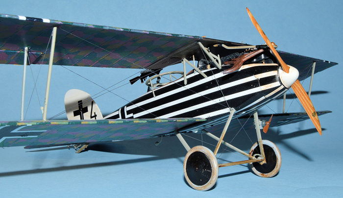
The undercarriage is a relatively simple installation. Complete as much of it as possible before installing, including the wheels and wheel covers. I predrilled small holes in locations on the axle bar for rigging. Wingnut wheels are attached to the undercarriage by means of slide-on C-shaped holders which are then hidden by the outer wheel covers. It’s much easier to do this when the undercarriage is not attached to the aircraft.
Next to be added were the rudder and fin. The fin fits into a slot at the end of the fuselage. By the time I added it, the fuselage was painted and decaled, so I did a lot of test fitting and enlarging of the slot so it would fit well. The fin fit snugly so I used a small amount of glue to secure it. I didn’t want the glue oozing out onto the fuselage, so I breathed a sigh of relief when it was cleanly in place. The tail skid fits into a slot in the fuselage interior, and a thick chord or wire runs from the skid to the rear ‘V-shaped’ bumper underneath the rear of the fuselage. It appears to be a type of shock absorber for the tailskid.
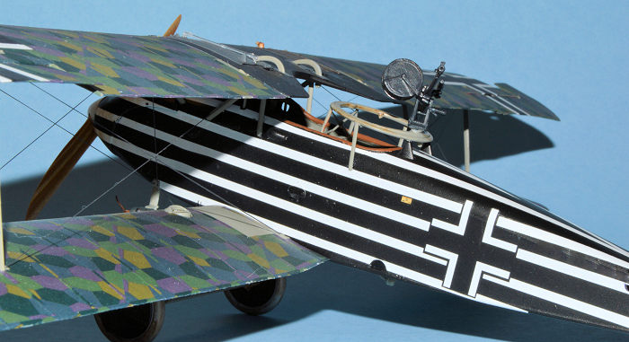
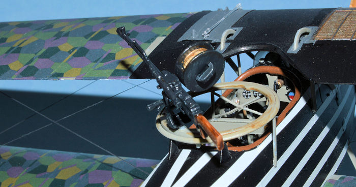
At this point I returned to the observer’s gun ring and attached it to the four points on the front and rear mounts on the fuselage. Once these had set up, I then added the two remaining struts that attach to the underside of the gun ring and then to the fuselage on each side. After assembling the observer’s machine gun, attachment stand, gun magazine and ammo belt, the completed assembly was attached to the gun ring. Next the propeller and spinner were added. I used a wooden Niendorf prop made by Proper Plane and was pleased with the result. I had to do some modification of the backing plate so the propeller would fit on it as the kit supplied props and plate are designed to fit together, unlike the wooden prop I used. There are some optional attachments the modeler can add to the aircraft such as flares, grenades, racks and a flare gun, but I decided not to add any of them.
 Rigging was accomplished using EZ Line, following the
kit instructions with some help from the Windsock Datafile. I did not use any
turnbuckles, although the interplane struts each have one at the lower end.
After attaching the rigging line to the top wing, I simply ran it through the
turnbuckle and attached it with CA glue. The other rigging was done by gluing
one end to the top wing, then cutting the line about a half inch short of its
destination, then inserting it into the small hole that had been filled with a
drop of CA glue. After holding the line in place about 30 seconds until it was
secure, I moved on the next one. Rigging the tail section involved gluing a
piece of EZ Line into the small holes at the back of the fuselage and, once dry,
attaching the lines to the appropriate control horn. When dry I trimmed the line
off and touched up the control horn with a spot of paint. With the rudder, I
actually drilled a small hole in the control horns and ran the rigging line
through the hole and attached it with CA glue. As WWI aircraft go, the
Halberstadt is pretty simple to rig.
Rigging was accomplished using EZ Line, following the
kit instructions with some help from the Windsock Datafile. I did not use any
turnbuckles, although the interplane struts each have one at the lower end.
After attaching the rigging line to the top wing, I simply ran it through the
turnbuckle and attached it with CA glue. The other rigging was done by gluing
one end to the top wing, then cutting the line about a half inch short of its
destination, then inserting it into the small hole that had been filled with a
drop of CA glue. After holding the line in place about 30 seconds until it was
secure, I moved on the next one. Rigging the tail section involved gluing a
piece of EZ Line into the small holes at the back of the fuselage and, once dry,
attaching the lines to the appropriate control horn. When dry I trimmed the line
off and touched up the control horn with a spot of paint. With the rudder, I
actually drilled a small hole in the control horns and ran the rigging line
through the hole and attached it with CA glue. As WWI aircraft go, the
Halberstadt is pretty simple to rig.
| COLORS & MARKINGS |
I began painting by spraying a coat of Model Master RLM Gray on the fuselage walls. I also painted the instrument panel, engine bearers and some other interior components this color. The floorboard, pilot’s seat and fuselage frames were all painted in a wood grain finish consisting of a base coat of Model Master Tan glazed with Griffin’s Burnt Umber. Portions of the frame were covered in kit supplied lozenge camouflage, so these areas were given a coat of Future beforehand. The instrument panel and various dials were applied with decals and, in some cases, given a drop of clear parts glue to represent glass covers. The hand pressurized air pump was painted brass with the handle black. The wireless aerial reel was given the wood grain treatment. The control column, rudder pedals and aileron control rods were all painted black.
The engine was painted per kit instructions with the crankcase and rocker boxes painted aluminum, the cylinders, intake manifold and various pipes Model Master GunMetal, and a few parts picked out in brass. Decals were applied to the engine in various locations, and the whole thing given a wash of thinned Burnt Umber and set aside to dry. The exhaust pipe was originally painted Gunze Burnt Iron, then drybrushed with Model Master Rust. The exhaust pipe opening was also drybrushed with dark gray to represent smoke stains. The Spandau and Parabellum machine guns were both painted with MM Gun Metal. The ammo belt was painted brass, then overpainted with a thin line of Sail Color to represent the fabric holding the bullets in place.
 As mentioned earlier, the completed fuselage was given
a primer coat of Model Master Light Ghost Gray enamel, then sprayed with a few
coats of Model Master Semi-Gloss Black Acrylic. Once dry it was sprayed with
Future until glossy, then I began the process of applying the white stripe
decals. The decals come in various sections such as right and left fuselage
halves, top and bottom, cowlings, etc. The key is to take your time, study the
photos and drawings and be careful. The lower stripe on each fuselage side wraps
slightly around the bottom of the fuselage, but this is not evident in the
pictures. I presume you could trim this little bit off, but I didn’t think it
was worth the risk of damaging the decal so I left it alone. I don’t know if the
real aircraft had this little extra or not.
As mentioned earlier, the completed fuselage was given
a primer coat of Model Master Light Ghost Gray enamel, then sprayed with a few
coats of Model Master Semi-Gloss Black Acrylic. Once dry it was sprayed with
Future until glossy, then I began the process of applying the white stripe
decals. The decals come in various sections such as right and left fuselage
halves, top and bottom, cowlings, etc. The key is to take your time, study the
photos and drawings and be careful. The lower stripe on each fuselage side wraps
slightly around the bottom of the fuselage, but this is not evident in the
pictures. I presume you could trim this little bit off, but I didn’t think it
was worth the risk of damaging the decal so I left it alone. I don’t know if the
real aircraft had this little extra or not.
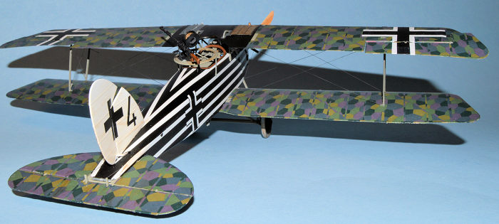
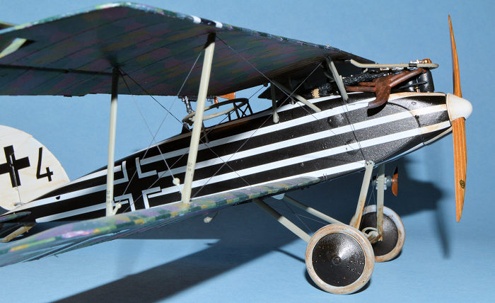
I painted the wings and horizontal tailplane with RLM Gray, then coated it all with several coats of Future to prepare them for lozenge decals. I used the kit supplied lozenge which represents the lozenge that was applied at a 45 degree angle on the Halberstadt. I applied the underside first, then the topside so the front rib tape would fold over the edge onto the underside section. Wingnut uses Cartograf decals which, although good, don’t work the best for lozenge because they are not solvent friendly, making it difficult to conform the lozenge to the curves and angles of the aircraft. It took repeated applications of MicroSet and MicroSol to get the decal edges to ultimately lay down. I plan to try Aviattic lozenge decals next time, as they have gotten rave reviews from modelers who have used them. Once the lozenge had dried, I sprayed it with a light coat of Future and applied the wing crosses, then later sprayed a light coat of Model Master Satin to tone down the gloss. I sprayed the middle section of the upper wing with a muddle of red brown and green on the underside, but with solid black on the topside. The instructions were undecided if this area was also painted in the red brown/green mix or if it was black. I decided to go with black because it looked better to me with the black and white striped fuselage. The radiator was painted aluminum then weathered with a wash of Burnt Umber. The top wing fuel tank was painted dark gray. Note the thin clear piece on top to represent the glass tube used to determine the level of fuel in the tank.
 The interplane and cabane struts were painted RLM
Gray, as were the radiator pipes. The undercarriage struts and the tail skid
were also painted RLM Gray. I painted the bungee cords with Gunze Sail Colcor.
The wheel covers were painted black, and the tires light gray. The undercarriage
was weathered with a Burnt Umber wash. I also applied the wash to the underside
of the fuselage, and to areas around the engine.
The interplane and cabane struts were painted RLM
Gray, as were the radiator pipes. The undercarriage struts and the tail skid
were also painted RLM Gray. I painted the bungee cords with Gunze Sail Colcor.
The wheel covers were painted black, and the tires light gray. The undercarriage
was weathered with a Burnt Umber wash. I also applied the wash to the underside
of the fuselage, and to areas around the engine.
The fin and rudder were painted white, sprayed with Future and decals applied. The spinner was also painted white and very lightly weathered. I applied some Future to the propeller, let it dry and then applied the Niendorf propeller logos. I sprayed another light coat of Satin over the whole model and, once dry, removed the masking tape from the windscreen. After several weeks of off again on again modeling my Halberstadt was finished.
| CONCLUSIONS |
I first built a model of a Halberstadt when I built the old Aurora kit sometime around 1963. Later it was resurrected as the K&B kit in the 1970s and I built that one. I later built the Blue Max kit, a much improved kit over the previous ones. At some point I even built the Guillows balsa wood kit with the “18 inch wingspan.” As much as I enjoyed all those kits, it was very exciting to see Wingnut Wings produce a super high-quality kit of this famous German WWI aircraft. The kit did not disappoint, and I’m glad I have two more in my kit stash to build in the future. Unfortunately, we will not be seeing any new Wingnut kits for the foreseeable future. The company announced that it was shutting down about six weeks ago with no word on what is going to happen to the company’s assets. There is speculation that the company’s forays into large and unusual aircraft such as the Felixstowe and Gotha bomber used up a lot of cash and didn’t offer a reasonable time frame for the recovery of their investment. When Wingnut Wings first started selling kits in 2009, founder and patron Sir Peter Jackson stated that they “were not a market driven company” and they would produce the kits that they were interested in producing. He also said that he wasn’t looking to make a lot of money from the company, but he “didn’t want to lose money either.” Although no official reason has been given for the shutdown, it certainly looks to observers that Mr. Jackson got tired of losing money on his expensive hobby. Whatever the reason, diehard WWI modelers the world over are grateful for the terrific kits they did produce. A lot of them, like me, were able to accumulate enough of a stash to keep us busy for several years to come.
| REFERENCES |
Windsock Datafile 27, “Halberstadt Cl.II,” P.M. Grosz, 1999.
Wikipedia, “Halberstadt Cl.II,” 2020.
Wingnut Wings kit instructions.
Otis Goodin
26 October 2020
Copyright ModelingMadness.com
If you would like your product reviewed fairly and
fairly quickly, please
contact
the editor or see other details in the
Note to
Contributors.