| KIT #: | 32065 |
| PRICE: | $80.00 |
| DECALS: | Five options |
| REVIEWER: | John Summerford |
| NOTES: |
| HISTORY |
Hugo Junkers received a patent in 1912 for a wing planform featuring a thick cantilever structure. The patent was featured on the experimental two-seat, steel skinned J-1 rolled out in November of 1915. After flight testing, Junkers received a contract for six single-seat fighters, model J-2. The steel skin proved to make the J-2 too heavy for front line duties. Junkers privately developed the corrugated, duralumin skinned J-3 during 1916. Work on that design was halted when Junkers received a contract to produce the J-4, an armor-plated ground attack biplane. Concurrently, design work was done for three other aircraft. The J-5 was a paper project with the engine behind the pilot. The J-6 was a parasol design only a few parts were fabricated.
 As the J-4
went into production in 1917 with the military designation J-1, work on the J-7
continued. It featured a single-seat, a frame made from duralumin tubes and
skinned in corrugated duralumin sheets. It led to a follow-on two-seat J-8
design which led to a production version J-10, military designation Cl-1, in
March of 1918.
As the J-4
went into production in 1917 with the military designation J-1, work on the J-7
continued. It featured a single-seat, a frame made from duralumin tubes and
skinned in corrugated duralumin sheets. It led to a follow-on two-seat J-8
design which led to a production version J-10, military designation Cl-1, in
March of 1918.
The design of the J-7 continued to be refined and was part of demonstration competition in January, 1918. It was found lacking in maneuverability and downward visibility. More refinements resulted in the J-9 and a pre-production aircraft was first flown in May of 1918. Further tweaks, mostly regarding the Mercedes engine, resulted in the production version, now designated D-1 by August. It was the first all-metal, cantilever-wing fighter in service.
The J-9/D-1 entered service too late to have any impact on the war, but the few in service afterward performed well in skirmishes between Germine Freikorps and Bolshevik forces in the Baltic during 1919. Junkers was only able to produce 40 D-1s, most of them after the armistice.
| THE KIT |
 Wingnut
Wings did not deviate from their usual boxing practices. A sturdy box holds four
light gray styrene sprues, ah individually bagged. (Although, they are labeled
A, B, D, and E.) Another bag holds the decal sheet and photo-etch fret. Sprue E
is devoted the engine and has 48 parts. Total parts count is 118 styrene and 11
photo-etch pieces, four of which are the two-part cooling jackets for the guns
if one wishes to forego the molded guns. Four different propellers are also
included.
Wingnut
Wings did not deviate from their usual boxing practices. A sturdy box holds four
light gray styrene sprues, ah individually bagged. (Although, they are labeled
A, B, D, and E.) Another bag holds the decal sheet and photo-etch fret. Sprue E
is devoted the engine and has 48 parts. Total parts count is 118 styrene and 11
photo-etch pieces, four of which are the two-part cooling jackets for the guns
if one wishes to forego the molded guns. Four different propellers are also
included.
The decals are aligned and show dense color. 78 decals cover the five options, stencils, and instrument faces for the panel. Paint options for the D-1 are; two mauve and light green camouflage patterns over light gray, two brown over light gray, and one unpainted aluminum. All but one of the options include a white rudder.
Instructions are printed in color on gloss coated paper. Including the front and back cover, the instruction booklet is 24 pages and packed with useful information and photos. The paint color chart lists 23 colors.
| CONSTRUCTION |
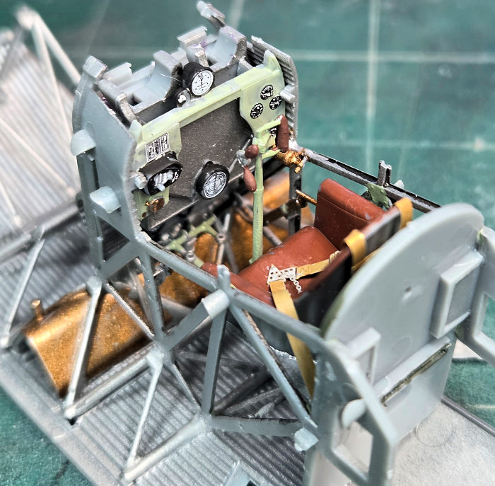
Beginning on page 3 of the booklet, construction starts with the cockpit and its associated framing which is attached to the lower fuselage. It is a lot like assembling a cockpit for a Hawker Typhoon or Hurricane. A lot of parts need detail painting, so the process is slow. The control column is in three pieces, and is fragile but installs solidly. I opted to install the instrument panel to the magazine/empty belt box before adding that subassembly to the frame.
 After the
cockpit, comes the engine assembly and installation. Since I prefer engine
compartments closed, I didn’t bother with the detail parts below the intake and
exhaust manifolds.
After the
cockpit, comes the engine assembly and installation. Since I prefer engine
compartments closed, I didn’t bother with the detail parts below the intake and
exhaust manifolds.
I later discovered that it is best to install the guns at this point and test fit the fuselage sides and the cover plate between the breaches so that they will mate properly. A lot of corrective surgery was done around the cockpit after the sides were glued at the tail plus when it came time to install the guns after painting, which was very annoying. This forced the installation of the molded guns as the photo-etch versions would likely be damaged.
A weakness in the instructions is that they show parts installed, not how they look coming off the sprue. Some sprue gates look like ears that are intended as a detail on the part. It would be clearer if both views were included. Also, an additional view from another angle of the part installed would be helpful. (I hope the good folks at Kotare consider these suggestions.)
Once the fuselage sides and engine compartment are assembled, the rest of the build is simple and quick.
| COLORS & MARKINGS |
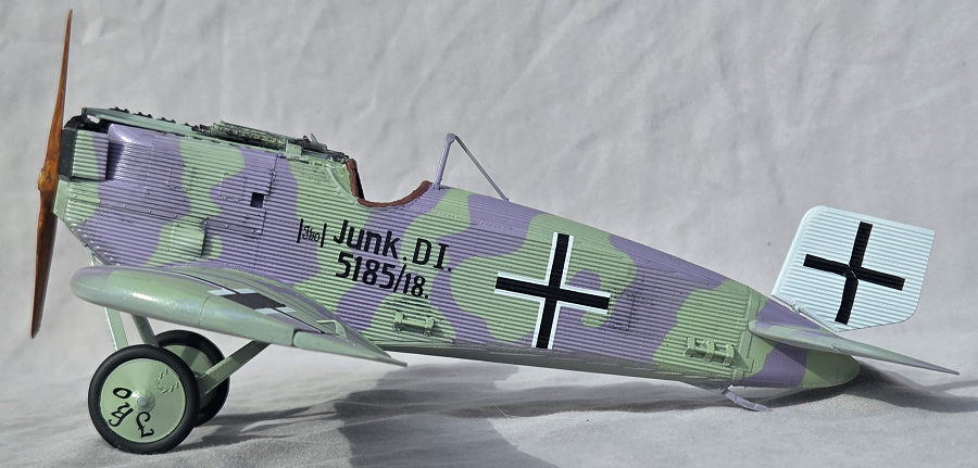
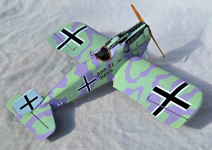
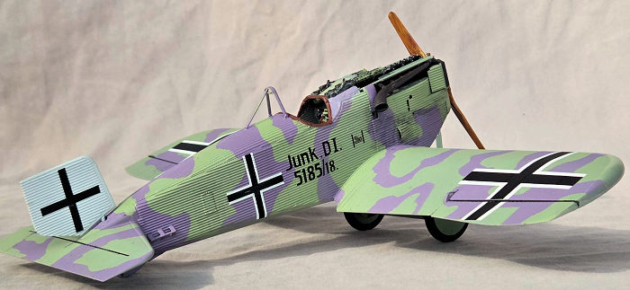
Aircraft option letter A was chosen because of its uniqueness. I hold two Fine Art degrees and I never would have paired up these two colors, but, somehow, they look good together. (My sweetheart think they would look good in a sweater. I don’t know if I’d go THAT far.) The hues appear in German lozenge patterns, so they are not uncommon and I suspect that they were the only paint that was available. The paint chart in the instructions describes how to mix Tamiya and Humbrol paints to get the proper colors. In this case Tamiya’s were used.
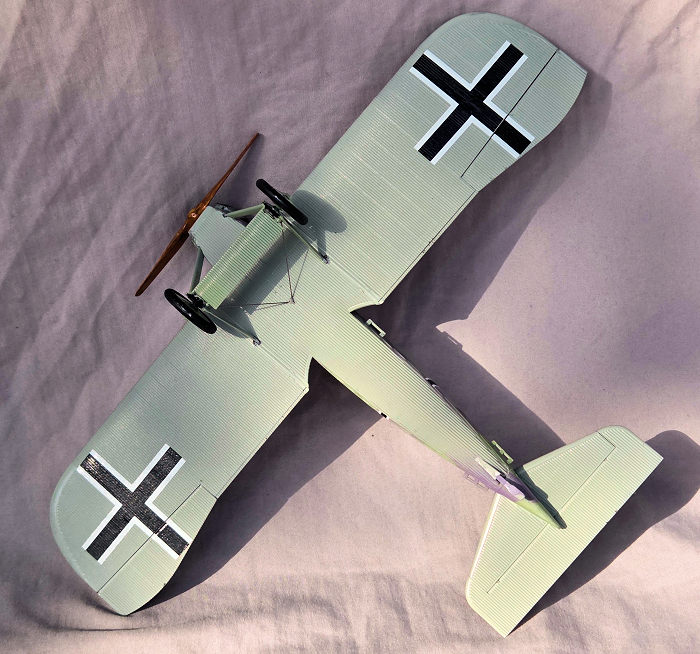
As is my usual practice, a rattle can of automotive primer was the first coat. The rudder was painted white. Wingnut Wings could not find definitive proof of the color for the undersides. It is some kind of gray or blue gray. Light ghost gray was chosen.
 For the
upper surfaces, the light green color was laid down first. Various methods of
masking were employed for the mauve paint. (There! I typed the word “mauve”)
Foam packing material filled the openings before the green coat while tape, two
liquid masks of different viscosities, and masking putty prepared the model for
the next color. Two coats of clear gloss were applied in preparation for the
decals.
For the
upper surfaces, the light green color was laid down first. Various methods of
masking were employed for the mauve paint. (There! I typed the word “mauve”)
Foam packing material filled the openings before the green coat while tape, two
liquid masks of different viscosities, and masking putty prepared the model for
the next color. Two coats of clear gloss were applied in preparation for the
decals.
By using the corrugations as guides, it is easy to get the decals straight. Because of the corrugations, there is no other choice either. Some of the decals resisted any maneuvering once they hit the surface and one didn’t move at all. Some setting fluid was used to get the decals into the troughs. Clear flat is the final coat.
After the afore mentioned drama with the guns, their troughs were added and then the exhaust pipes. The landing gear was assembled and offered up to the fuselage, The trickiest task was installing the wheel retainer clips. Once the glue cured, the only rigging for the model is .015 size material that runs from the spreader ends to the bottom of the fuselage. Steel music wire was used for this.
If desired, the rudder can be glued into place, but it is engineered to snap into place and swivel. That left the prop as the final addition.
| CONCLUSIONS |
 This is
probably the simplest kit Wingnut Wings produced. I’m still annoyed about the
lack of clarity regarding the fit of the fuselage sides to the interior
framework. Other than that, it is an easy model to assemble. However, it does
require formulating a sequence of painting parts and assembly before starting.
This model was completed over the course of eight days, which says a lot about
the quality of the kit.
This is
probably the simplest kit Wingnut Wings produced. I’m still annoyed about the
lack of clarity regarding the fit of the fuselage sides to the interior
framework. Other than that, it is an easy model to assemble. However, it does
require formulating a sequence of painting parts and assembly before starting.
This model was completed over the course of eight days, which says a lot about
the quality of the kit.
This the fifth in a series of five models featuring corrugated skin. I dreaded dealing with seams, but they turned out to be a simple issue. Preparing for, and laying down, the decals was the most difficult aspect of finishing each plane. It got easier with each project, but I had issues with all of them. Due to so many other projects that I want to do, I won’t build another any time soon.
It’s interesting looking at the progression of the engineering by Junkers on the D-1, F-13, and Ju-52. By the time they reached the Ju-52, they had wrung out all that they could from the corrugated skin construction.
16 October 2025
Copyright ModelingMadness.com. All rights reserved. No reproduction in part or in whole without express permission from the editor.
If you would like your product reviewed fairly and fairly quickly, please contact the editor or see other details in the Note to Contributors.