| KIT #: | 6003 |
| PRICE: | $50.00 or so |
| DECALS: | Four options |
| REVIEWER: | Rob Hart |
| NOTES: |
| HISTORY |
The Zeppelin is a type of rigid airship. It is named after the German Inventor, Ferdinand Von Zeppelin, who pioneered rigid airship development at the beginning of the 20th century. Zeppelins were first flown commercially in 1910 and by 1914 had carried over 10,000 fare-paying passengers on over 1500 flights. During WWI, the German military made extensive use of Zeppelins as bombers and as scouts. After WWI, commercial zeppelin flights resumed until the crash of LZ 129 “Hindenburg” in 1937, along with political and economic developments in Germany brought about the demise of the rigid airship.
 The principal feature of
the Zeppelin's design was a fabric-covered, rigid metal framework of transverse
rings and longitudinal girders enclosing a number of individual gas bags. This
allowed the craft to be much larger than non-rigid airships. The framework was
duralumin, a combination of aluminum, copper, and two or three other metals.
Early Zeppelins use rubberized cotton for the gasbags, but most later craft used
Goldbeater's skin made from cattle gut. Zeppelins were propelled by several
internal combustion engines, mounted in gondolas attached outside the structural
framework. German Zeppelins used hydrogen gas for buoyancy. German airships used
by the military carried crews of 15-18 men.
The principal feature of
the Zeppelin's design was a fabric-covered, rigid metal framework of transverse
rings and longitudinal girders enclosing a number of individual gas bags. This
allowed the craft to be much larger than non-rigid airships. The framework was
duralumin, a combination of aluminum, copper, and two or three other metals.
Early Zeppelins use rubberized cotton for the gasbags, but most later craft used
Goldbeater's skin made from cattle gut. Zeppelins were propelled by several
internal combustion engines, mounted in gondolas attached outside the structural
framework. German Zeppelins used hydrogen gas for buoyancy. German airships used
by the military carried crews of 15-18 men.
The Zeppelin in WWI:
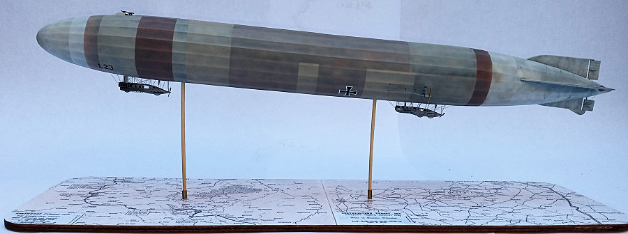
The German airships were operated separately by the Army and Navy. Navy Zeppelins were used primarily for reconnaissance missions. Early offensive operations by Army airships revealed that they were extremely vulnerable to ground fire, and several were lost. Aerial bombs had not been developed when the war began and early raiders dropped artillery shells instead. Zeppelins flew bombing, scouting, and maritime patrols on all fronts throughout the course of WWI with mixed success. 84 Zeppelins were built during WWI. Over 60 were lost, roughly equally divided between accidents and combat. Zeppelin crews suffered a 40% casualty rate. Zeppelin L 23, the subject of the review model, flew 51 reconnaissance missions and 3 bombing raids. It was shot down on on April 23, 1917 by 2nd Lt. Bernard A. Smart flying a Sopwith Pup that had been launched from a platform on the main turret of the light cruiser, HMS Yarmouth. Zeppelins flew 51 bombing raids against England alone, killing 557 people and wounding 1358. However, it can be argued that the raids were most effective in causing the diversion of men and material from the front lines to the defenses of the civilian populations.
| THE KIT |
The kit has 33 plastic parts and 30 photo-etched brass parts. Four of the plastic parts are for the display stands and are molded in clear plastic. Decals are provided for four markings options, one of which is a “what if” with a speculative camouflage scheme. Color call-outs reference Ammo paints. The 15 page instruction booklet illustrates the 13 step construction sequence and provides full color painting and decal placement guides.
| CONSTRUCTION |
 This is the second Takom Q
Class Zeppelin kit that I have built. I completed the first one in the spring of
2023 and shortly afterwards it was damaged beyond repair when I accidentally
dropped it. I was really angry with myself, but accepted the loss and tossed the
parts in the spares box. However, my wife expressed much disappointment when I
told her of the model's fate and stated that of all the models that I had built,
this one was her favorite, and encouraged me to build another one. With that in
mind, I decided to build the model that is the subject of this review. Besides
which, there were a few issues that came up in the first build that I wanted to
try to improve upon.
This is the second Takom Q
Class Zeppelin kit that I have built. I completed the first one in the spring of
2023 and shortly afterwards it was damaged beyond repair when I accidentally
dropped it. I was really angry with myself, but accepted the loss and tossed the
parts in the spares box. However, my wife expressed much disappointment when I
told her of the model's fate and stated that of all the models that I had built,
this one was her favorite, and encouraged me to build another one. With that in
mind, I decided to build the model that is the subject of this review. Besides
which, there were a few issues that came up in the first build that I wanted to
try to improve upon.
The hull comes in eight parts, two each of forward, rear and center sections all split vertically and two long, flat, and narrow strips that represent the sections of the lower hull that the gondolas attach to. The halves of the forward, rear, and center sections fit each other without any issues, but joining the sections to each other reveals alignment issues. No matter how much dry fitting that I did, attaching the hull sections to each other left steps and gaps. Because the hull has prominent ridges and valleys to represent how the fabric covering was attached to the internal framework, very careful filling and sanding was required to maintain the exterior contours. I was eventually able to satisfactorily eradicate the bad seams with gap willing super glue and careful sanding with multiple grits of Tamiya sanding sponges.
The kit provides four fins/stabilizers and four separate rudders/elevators to reproduce the subject's cruciform tail surfaces. The fins/stabilizers have pins that fit into holes at the bottoms of grooves molded in the sides of the hull. I knew from the previous build that despite what looked like a positive attachments, the fit was loose and sloppy and the pins had a tendency to break off. To provide a stronger assembly, I replaced the pins with short lengths of 1/16” steel rods. The rudders and elevators are molded integrally with their opposite numbers by lengths of thin styrene rod. The manufacturer's intention is for the rods to be trapped between the hull halves so the rudders and elevators will be movable. I felt that completing the assembly to accommodate the moving parts would make eliminating the seams on the hull halves very difficult, so I cut the inter-connecting rods in the middle of their length. After I had finished eradicating the upper and lower seams on the hull and attaching the fins and stabilizers, I threaded the ends of the rods through the holes in the hull before gluing them in position with thin super glue.
The forward gondola is made
up of left and right halves, a roof,.and a two piece assembly that encloses the
main control room. The assembly is completed by adding four photo-etched grab
rails for the ground crew and the exhaust pipe for the single engine in the rear
of the gondola. I held off on attaching the propeller until later in the
assembly. The rear gondola is made up of left and right halves, four
photo-etched grab rails, and three exhaust pipes. Again, I left off the
propeller until later in the assembly process, The photo-etched grab rails
proved to be extremely fragile and bent if I even so much as breathed on them.
After re-attaching and straightening them several times, I ended up replacing
them with .004”stainless steel music wire . The gondolas attach to two sections
of the lower hull. These sections are molded as thin strips of styrene
incorporating the bomb bay doors. The doors are represented as scribed
rectangles. The gondolas are attached to the sections by very thin lengths of
photo-etched brass before the sections are joined with the hull. However, the
sections are a poor fit with the hull and the attachment points of the gondolas
photo-etched connections lies right on the seams where the sections join with
the hull. I decided to glue the sections to the hull and clean up the seams
before I attached the gondolas. In fact, I did not attach the gondolas until
after the hull and gondolas had been completely painted. I knew from the
previous build that the kit provided photo-etched connection bracing that joins
the gondolas to the hull sections was very fragile and prone to bending, and
decided to look for an alternative. The smallest size (.2 mm) of SBS 1/72
generic photo-etch rigging came the closest to what I wanted. The wires are
flat, stiff, already silver in color, and much stronger than the kit's parts.
The forward gondola not only attaches to the hull section by the photo etched
bracing , but also by two styrene pylons that are molded on the roof of the
gondola. The upper ends of the pylons plug into indentations in the surface of
the hull section making for a fairly easy assembly. The rear gondola however, is
attached to the hull section by only the photo etched bracing. In addition,
framework that provides cradles, booms, and bracing for the outboard propellers
attaches to the rear gondola and the hull. This framework is provided in the kit
as photo-etched brass and some of the pieces needed to be carefully bent at
various angles. After many tries, I managed to get the gondola and all of the
bracing attached and aligned satisfactorily. I had left the photo-etched brass
framework unpainted until after it was attached to the gondola and the hull. I
knew from the previous build that the amount of handling required to get the
framework attached and aligned would cause the paint to chip and rub off
necessitating, a difficult and tedious touch up job. I preferred to mask off the
hull and paint the framework after it was glued in position. Not easy and I
still ended up having to do some paint touch up, but the result looked much
better than what I had achieved on the previous build.
. The gondolas attach to two sections
of the lower hull. These sections are molded as thin strips of styrene
incorporating the bomb bay doors. The doors are represented as scribed
rectangles. The gondolas are attached to the sections by very thin lengths of
photo-etched brass before the sections are joined with the hull. However, the
sections are a poor fit with the hull and the attachment points of the gondolas
photo-etched connections lies right on the seams where the sections join with
the hull. I decided to glue the sections to the hull and clean up the seams
before I attached the gondolas. In fact, I did not attach the gondolas until
after the hull and gondolas had been completely painted. I knew from the
previous build that the kit provided photo-etched connection bracing that joins
the gondolas to the hull sections was very fragile and prone to bending, and
decided to look for an alternative. The smallest size (.2 mm) of SBS 1/72
generic photo-etch rigging came the closest to what I wanted. The wires are
flat, stiff, already silver in color, and much stronger than the kit's parts.
The forward gondola not only attaches to the hull section by the photo etched
bracing , but also by two styrene pylons that are molded on the roof of the
gondola. The upper ends of the pylons plug into indentations in the surface of
the hull section making for a fairly easy assembly. The rear gondola however, is
attached to the hull section by only the photo etched bracing. In addition,
framework that provides cradles, booms, and bracing for the outboard propellers
attaches to the rear gondola and the hull. This framework is provided in the kit
as photo-etched brass and some of the pieces needed to be carefully bent at
various angles. After many tries, I managed to get the gondola and all of the
bracing attached and aligned satisfactorily. I had left the photo-etched brass
framework unpainted until after it was attached to the gondola and the hull. I
knew from the previous build that the amount of handling required to get the
framework attached and aligned would cause the paint to chip and rub off
necessitating, a difficult and tedious touch up job. I preferred to mask off the
hull and paint the framework after it was glued in position. Not easy and I
still ended up having to do some paint touch up, but the result looked much
better than what I had achieved on the previous build.
| COLORS & MARKINGS |
Surprisingly, information on the Zeppelin's fabric covering was not readily available. Various sources disagreed on whether the the fabric was cotton, linen, or canvas. I chose to go with linen because I thought that cotton would not have the needed strength and that canvas would have been too heavy. I found even less information on what kind of waterproofing was applied to the fabric. I'm guessing that it was some kind of dope similar to what was applied to contemporary fabric-covered aircraft.
 The best description of the
base color of the fabric covering that I found stated that it was “brown, like
the color of wrapping paper”. Another source stated that the fabric “darkened
with age and exposure to moisture.” The fabric covering was formed from large
panels sewed together and those panels had to be frequently replaced due to
mold, damage, and the effects of the weather causing the fabric to take on a
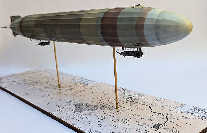
patchy and soiled appearance. I tried to reproduce the appearance of the fabric
covering by applying a base coat of Tamiya white lacquer primer followed by
spraying a mottling of gloss black Tamiya acrylic in the “valleys” between the
representations of the longitudinal girders. I then sprayed thin coats of
various tans, buffs, and browns mixed from Tamiya acrylics. I masked off
different sized panels between each individual color. I think the result
achieved what I wanted, but I also kind of wish the colors had a little less
contrast with each other. I painted the gondolas with Alclad II Aluminum and
colored in the windows with a black Pigma Micron .005 pen. I applied a streaky
burnt umber oil paint wash on the propellers followed by a coat of Tamiya Clear
Yellow and Clear Orange mixed 70/30. I used the same Tamiya Clear Orange and
Clear Yellow mix to paint the floor of the machine gun platform on the top of
the hull. I painted the guns and their mounts with Alclad II steel. After clear
coating the hull with Tamiya X22 clear, I applied the only decals, the aircraft
ID letter and number and the national insignia, on both sides of the lower hull.
The decals went on with no drama.
The best description of the
base color of the fabric covering that I found stated that it was “brown, like
the color of wrapping paper”. Another source stated that the fabric “darkened
with age and exposure to moisture.” The fabric covering was formed from large
panels sewed together and those panels had to be frequently replaced due to
mold, damage, and the effects of the weather causing the fabric to take on a
patchy and soiled appearance. I tried to reproduce the appearance of the fabric
covering by applying a base coat of Tamiya white lacquer primer followed by
spraying a mottling of gloss black Tamiya acrylic in the “valleys” between the
representations of the longitudinal girders. I then sprayed thin coats of
various tans, buffs, and browns mixed from Tamiya acrylics. I masked off
different sized panels between each individual color. I think the result
achieved what I wanted, but I also kind of wish the colors had a little less
contrast with each other. I painted the gondolas with Alclad II Aluminum and
colored in the windows with a black Pigma Micron .005 pen. I applied a streaky
burnt umber oil paint wash on the propellers followed by a coat of Tamiya Clear
Yellow and Clear Orange mixed 70/30. I used the same Tamiya Clear Orange and
Clear Yellow mix to paint the floor of the machine gun platform on the top of
the hull. I painted the guns and their mounts with Alclad II steel. After clear
coating the hull with Tamiya X22 clear, I applied the only decals, the aircraft
ID letter and number and the national insignia, on both sides of the lower hull.
The decals went on with no drama.
| FINAL CONSTRUCTION |
 I planned to rig the model
and had drilled holes in the anchoring points of the hull, gondolas, and tail
surfaces before construction began.. The external.rigging on Zeppelins is only
evident on the tail and as bracing for the gondolas. I used .004” stainless
steel music wire for the rigging. With the rigging complete, I attached the
machine gun platform to the top of the hull and attached the propellers to the
aft ends of the gondolas and the outer rear ends of the outrigger booms.
Finally, I sprayed the entire model with a coat of Tamiya XF86 clear flat. The
kit provides a couple of cone shaped clear plastic stands that have shallow “U”
shaped cradles at their upper extremities. The bases of the cones are very small
in diameter and they are short enough that when the hull sits on the cradles,
the gondolas barely clear the ground. I felt that the stands were too wobbly and
unstable for my satisfaction and went about building a custom display stand. I
found a piece of scrap plywood in my garage, cut it down to 20” by 7”. and
rounded off the corners. I printed out a couple of WWI battlefield maps that I
found on the internet and glued them to the plywood. I drilled 3/16” holes in
corresponding locations of the base and the bottom of the hull and glued short
lengths of 3/16” OD and 1/8” ID brass tubing in the holes of the hull and the
bases. I then cut 6” lengths from 1/8” diameter bamboo BBQ skewers to elevate
the model above the base.
I planned to rig the model
and had drilled holes in the anchoring points of the hull, gondolas, and tail
surfaces before construction began.. The external.rigging on Zeppelins is only
evident on the tail and as bracing for the gondolas. I used .004” stainless
steel music wire for the rigging. With the rigging complete, I attached the
machine gun platform to the top of the hull and attached the propellers to the
aft ends of the gondolas and the outer rear ends of the outrigger booms.
Finally, I sprayed the entire model with a coat of Tamiya XF86 clear flat. The
kit provides a couple of cone shaped clear plastic stands that have shallow “U”
shaped cradles at their upper extremities. The bases of the cones are very small
in diameter and they are short enough that when the hull sits on the cradles,
the gondolas barely clear the ground. I felt that the stands were too wobbly and
unstable for my satisfaction and went about building a custom display stand. I
found a piece of scrap plywood in my garage, cut it down to 20” by 7”. and
rounded off the corners. I printed out a couple of WWI battlefield maps that I
found on the internet and glued them to the plywood. I drilled 3/16” holes in
corresponding locations of the base and the bottom of the hull and glued short
lengths of 3/16” OD and 1/8” ID brass tubing in the holes of the hull and the
bases. I then cut 6” lengths from 1/8” diameter bamboo BBQ skewers to elevate
the model above the base.
| CONCLUSIONS |
Well, it is a fairly large model of a WWI Zeppelin and that, in and of itself, makes it unusual and eye-catching. However, I can only recommend the kit to builders that have a lot of experience working with photo-etched parts. I think that experience with building small scale ship models would also come in handy. After completing the model I showed it to my wife and reminded her that she said the previous model was her favorite and that she had encouraged me to build the second model. Her response: “I said that”?
Rob Hart
25
September 2024 Copyright ModelingMadness.com. All rights reserved. No
reproduction in part or in whole without express permission. If you would like your product reviewed fairly and fairly quickly, please
contact
the editor or see other details in the
Note to
Contributors.