| KIT #: | |
| PRICE: | |
| DECALS: | |
| REVIEWER: | Stephen Foster |
| NOTES: | Scratch built with home made decals |
| HISTORY |
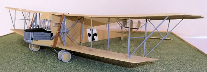
The Siemens-Schuckert R. 1 Riesenflugzeug (R-plane, giant aircraft), was the product of Bruno and Franz Steffen who were engineers who had built small monoplanes at their factory near Kiel, and wanted to build a large multi-engined transport aircraft because they believed that these and not airships would be the future of air transport. In October 1914 they were able to put their ideas to the aviation inspectorate in Berlin. The appearance of Sikorsky's four-engined Grand in 1913 had had a profound effect on nascent air ministries throughout the world and while building a large airframe was straightforward, finding suitably powerful and reliable engines was an altogether different matter.
The Steffen brothers' factory was too small to undertake
the construction of the large project that they proposed, so Siemens-Schuckert
Werke (SSW) were asked to undertake the construction.The machine was designed by
the Steffen brothers and the R1 made its maiden flight on May 24 1915. It was
powered by three
 150 hp Benz Bz. III engines which were mounted in the nose and
connected to a common gearbox. Two drive shafts were coupled to the propellors
via hear housings mounted on the struts between the wings. This allowed a
mechanic to be able to service the engines when in flight: communication between
the pilots and the mechanic was by written notes as the noise levels were so
great.
150 hp Benz Bz. III engines which were mounted in the nose and
connected to a common gearbox. Two drive shafts were coupled to the propellors
via hear housings mounted on the struts between the wings. This allowed a
mechanic to be able to service the engines when in flight: communication between
the pilots and the mechanic was by written notes as the noise levels were so
great.
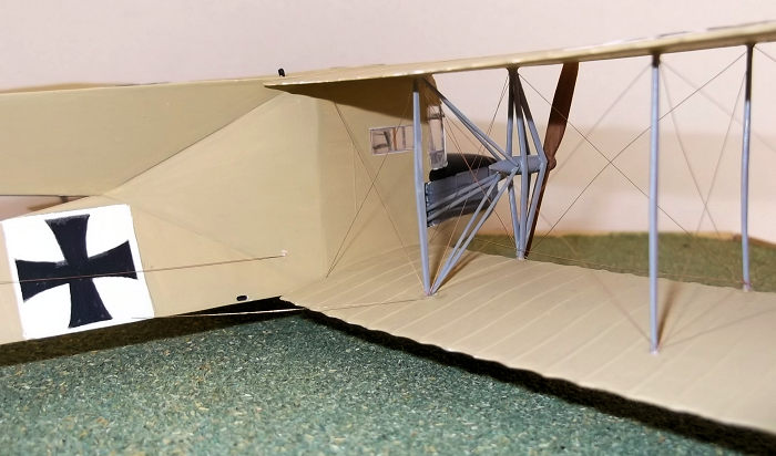
The aircraft had a steel tubing framework for the fuselage, the wings were from wood, and both were covered in fabric except for the nose which was partially covered in aluminium panels. The tail wheels were steerable and the whole machine weighed 5 tons. The unconventional fuselage shape was adopted so that machine guns could fire rearwards from positions in the fuselage to the rear fo the pilots. In the even no guns seem to have been carried by any of these machines. One early recurring problem was the failure of the propellor drive shafts, usually the universal joint near the struts. This was solved by adding stiffener tubes fore and aft of the transmission shafts. The R 1 made 24 orientation flights before it was handed to the air force for further evaluation and testing. On early August 1915 the machine had just taken off on a training flight when all three engines failed causing the machine to hit the ground from about 8 meters: the crew were fortunately unharmed but the aircraft wear severely damaged. It was returned to the SSWn factory and rebuilt.
In the summer of 1915 a new Sonderkommando (special init) was formed to operate with second generation giant aircraft: there was much to be learned about operating and flying these very large machines. The R1 was returned to Poland and used for further testing and training but was not considered reliable enough to be risked on actual bombing raids. It was badly damaged again inn March 1916 when being returned to Berlin when the airframe hit the side of a tunnel because the track bed had had moved. It was repaired again and sent to Doberitz as a training aircraft where it continued training pilots and flight mechanics: in 1917 it was recorded as having completed 97 training flights and 26 crew orientation flights. This machine had a longer service record than any other R type and no other centrally powered R-plane was as successful as the SSW R planes - a tribute to the Steffen brothers and their co-workers at SSW.
 Six more SSW R-types were built, all of them had a
re-designed and better streamlined nose, with a gun position in the front. The
150 hp Benz Bz III engines of the R1 were to be replaced by more powerful 240 hp
Maybach HS engines but these proved to be seriously problematical and so either
Mercedes D IV or Benz IV engines were fitted. Because the Benz engines were less
powerful and the Mercedes engines were heavier than the Maybach's it was decided
to increase the span of the wings of some machines to increase lift. On the R
VII the span reached its maximum of 38m with 6 bay wings but this caused the
handling characteristics to deteriorate. The RV certainly carried out some
bombing raids on the Eastern Front: the other machines were sent to the same
front for training and evaluation purposes before either crashing and being
written off or returning to Germany where they were used for training. These
machines gave invaluable service in helping ground personnel and aircrews
experience in operating large, complex aircraft from airfields in wartime
conditions, and in flying multi-engined aircraft. Although their front line
operations were very limited, they were nonetheless pioneers in a new branch of
strategic warfare.
Six more SSW R-types were built, all of them had a
re-designed and better streamlined nose, with a gun position in the front. The
150 hp Benz Bz III engines of the R1 were to be replaced by more powerful 240 hp
Maybach HS engines but these proved to be seriously problematical and so either
Mercedes D IV or Benz IV engines were fitted. Because the Benz engines were less
powerful and the Mercedes engines were heavier than the Maybach's it was decided
to increase the span of the wings of some machines to increase lift. On the R
VII the span reached its maximum of 38m with 6 bay wings but this caused the
handling characteristics to deteriorate. The RV certainly carried out some
bombing raids on the Eastern Front: the other machines were sent to the same
front for training and evaluation purposes before either crashing and being
written off or returning to Germany where they were used for training. These
machines gave invaluable service in helping ground personnel and aircrews
experience in operating large, complex aircraft from airfields in wartime
conditions, and in flying multi-engined aircraft. Although their front line
operations were very limited, they were nonetheless pioneers in a new branch of
strategic warfare.
| CONSTRUCTION |
There is a 1/144 vacuform kit of this type but I have lost my reference to it. In any event it will be a rare bird and is too small for me as I work in 1/72 scale.
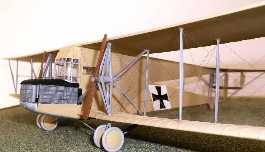
I started by building up the nose with the side and front radiators. I made the sides and front from 60 thou card and lined them with 20 thou rod to represent the cooling vanes of the radiators. The top and chin pieces were moulded from 30 thou card and glued into place to make up a sub-assembly. The cockpit interior was made from card for the pilot and co-pilot’s seats, and control wheels and other basic controls added as per the photographs of the cockpit shown in photos in the DataFile.
The wings were next. I started by bending some 40 thou
card to start the aerofoil shape and then glued a strip of 30 thou and 20 thou
card to the top. The upper wings are in two halves because the card was not long
enough to make the whole span in one piece. Similarly the lower wings are in two
parts, this time because there is a marked dihedral and I could not bend the
card to achieve this. The laminated plastic was sanded first with coarse and
later medium and fine glass paper and the joints of the plastic liberally filled
 with filler. Finally all the parts were sanded smooth so that the ribs could be
added: these were 10 x 30 thou strip. The ribs were in turn sanded to round off
the edges. The hole for the gunner was cut into the top wing before the halves
were joined. The the upper wing was joined using two small pins cut from a paper
clip and inserted holes which had been drilled into the ends of the wing halves.
The pins were held with superglue. The top wing was joined using conventional
plastic cement on the faces and more superglue for the pin ends: when dry the
joint was filled and sanded. The lower wing sections were joined in the same way
with pins and plastic cement but this time they had to be supported to obtain
the correct anhedral. Finally all the parts were sanded smooth so that the ribs
could be added with 10 x 30 thou strip. The ribs were in turn sanded to round
off the edges.The tail flying surfaces were cut from 30 thou plastic card which
was sanded to aerofoil section. The large horizontal surface had ribs added in
the same way as the wings.
with filler. Finally all the parts were sanded smooth so that the ribs could be
added: these were 10 x 30 thou strip. The ribs were in turn sanded to round off
the edges. The hole for the gunner was cut into the top wing before the halves
were joined. The the upper wing was joined using two small pins cut from a paper
clip and inserted holes which had been drilled into the ends of the wing halves.
The pins were held with superglue. The top wing was joined using conventional
plastic cement on the faces and more superglue for the pin ends: when dry the
joint was filled and sanded. The lower wing sections were joined in the same way
with pins and plastic cement but this time they had to be supported to obtain
the correct anhedral. Finally all the parts were sanded smooth so that the ribs
could be added with 10 x 30 thou strip. The ribs were in turn sanded to round
off the edges.The tail flying surfaces were cut from 30 thou plastic card which
was sanded to aerofoil section. The large horizontal surface had ribs added in
the same way as the wings.
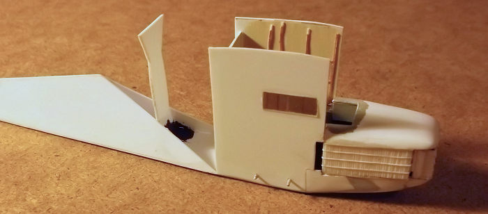
At this point I made a serious error in my first attempt
to make the triangular sections at the rear of the aircraft. Without going into
too much detail I assembled two rear parts and a central cab, but when I came to
assemble the rear, centre and nose sub-assemblies I found that the top wing was
7mm too close to the lower one. After much measuring and experimentation I found
that the cross-sections in the plans that I was using were not correct. I made
card templates of the triangular rear fuselage sections and used these to
determine the correct dimensions of the sides. I made two sides for the central
cabin and added some internal detail in the form of framing etc, a floor and a
rear panel - the latter was not there on the real machine but I needed one to
hold the sides when I assembled the nose and tail sub-units. 60-thou strips of
plastic were glued to the lower parts of the cockpit sides as two pieces of
paper clip had to be passed through to form pins to help strengthen the butt
joints of the lower wings to fuselage. New triangular fuselage sections were
constructed, this time the underside of the lower section was made long enough
to extend under the cockpit to join the base of the nose. I cut a bulkhead which
was shaped so that the edges
 matched the sides of the fuselage section between
the triangular rear and rectangular centre. Now I could construct the centre and
rear sub-assemblies by gluing the cockpit sides to the front of the bottom of
the lower fuselage triangle, with the rear panel of the cabin inserted to stop
the sides from falling about. Then the cockpit floor could be put in - this
rested on the small blocks added to the bottoms of the cockpit sides to hold the
reinforcing pins for the lower wing. The cockpit floor concealed the reinforcing
pins for the wings which were epoxied in place. The nose was attached to the
central cabin area and the bulkhead glued to the floor of the lower fuselage
triangle. The top wing was fixed to the cabin sides.
matched the sides of the fuselage section between
the triangular rear and rectangular centre. Now I could construct the centre and
rear sub-assemblies by gluing the cockpit sides to the front of the bottom of
the lower fuselage triangle, with the rear panel of the cabin inserted to stop
the sides from falling about. Then the cockpit floor could be put in - this
rested on the small blocks added to the bottoms of the cockpit sides to hold the
reinforcing pins for the lower wing. The cockpit floor concealed the reinforcing
pins for the wings which were epoxied in place. The nose was attached to the
central cabin area and the bulkhead glued to the floor of the lower fuselage
triangle. The top wing was fixed to the cabin sides.
When the above was completely dry, (ie after a night), the
upper fuselage triangular section could be lowered over the bulkhead and butted
against the rear of the top wing while a florist’s wire support strut was
inserted into upper and lower rear fuselage units and held with superglue.
Finally the triangular pieces which fill the gaps behind the cockpit were cut to
fit - each had to be trimmed and adjusted from the pieces which I had previously
made from using the card patterns mentioned above. These were then touched in
with some filler and again the whole assembly set aside to dry out. I fitted the
lower wings one at a time. The pins which I had put through the bottom of the
fuselage were to go into holes which I had drilled into the ends of the lower
wings. I had to tidy the ends of the wings with some thin card because the
laminations had left uneven edges. When I had dry fi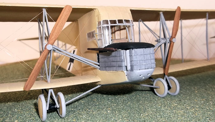 tted the wings and checked
that all was aligned I started with the starboard (right) wing. Superglue was
put on the ends of the pins and cement to the plastic edges of the wing. The
wing was then attached to the pins and supported while the cement dried. The
superglue dried quickly and held things in place but I decided to take no
chances and left everything for an hour. The struts had been pre-cut and shaped
from 30 x 60 thou Evergreen strip but they had to be trimmed to fit exactly. I
measured the gap with dividers and final trimming was done by offering the strut
to the hole. The inner rear strut was placed first and allowed to dry for 10
minutes, followed by the remaining vertical struts. The same procedure was the
followed for the port (left wing). When all the vertical struts were secure I
could add the diagonal outer bracing struts to the upper wing overhangs. The
horizontal tail surface was fixed to the top of the rear fuselage and the
bracing added from 20 x 30 thou Evergreen strip.
tted the wings and checked
that all was aligned I started with the starboard (right) wing. Superglue was
put on the ends of the pins and cement to the plastic edges of the wing. The
wing was then attached to the pins and supported while the cement dried. The
superglue dried quickly and held things in place but I decided to take no
chances and left everything for an hour. The struts had been pre-cut and shaped
from 30 x 60 thou Evergreen strip but they had to be trimmed to fit exactly. I
measured the gap with dividers and final trimming was done by offering the strut
to the hole. The inner rear strut was placed first and allowed to dry for 10
minutes, followed by the remaining vertical struts. The same procedure was the
followed for the port (left wing). When all the vertical struts were secure I
could add the diagonal outer bracing struts to the upper wing overhangs. The
horizontal tail surface was fixed to the top of the rear fuselage and the
bracing added from 20 x 30 thou Evergreen strip.
The gearboxes on the ends of the drive shafts were made from thick sprue which had been filed to shape. The gearbox bearer struts were made from Evergreen strip (30 thou x 40 thou), which had been sanded to aerofoil section. I measured the rear struts first and then bent them gently at the mid point before gluing them to the sides of the gearboxes. The front struts were attached to the gearboxes in turn. After the struts had been glued together both sub-assemblies could be inserted between the wings and glued into place. The cockpit glazing was moulded from thin acetate and the large hole in the front reflects what was present on the real aircraft. It was left open not because the pilots liked lots of fresh air because they were sitting behind three engines in the nose, but they wanted to make a rapid escape if the aircraft crashed!
| COLORS & MARKINGS |
 I made a mix of Humbrol enamels clear doped linen (103)
and natural wood (94) in a ratio of 3:2 and applied three thin coats. The
radiators were Humbrol dark sea grey (164) which were coated with matt varnish.
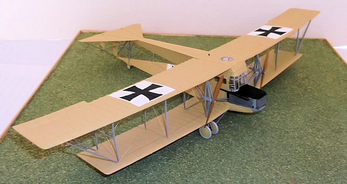
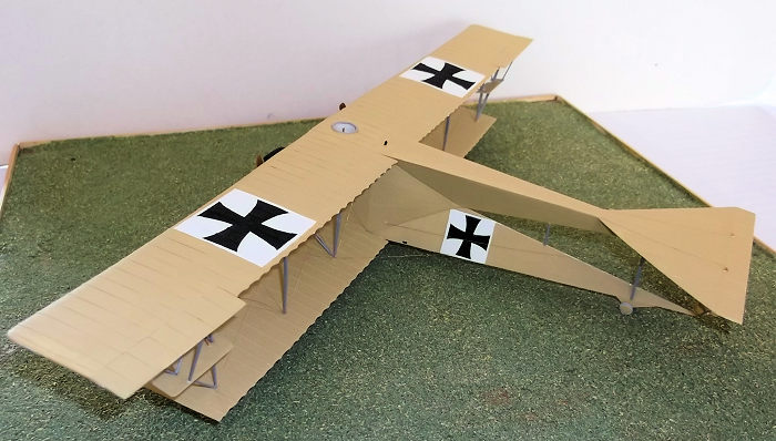
The anti-glare panel on the top of the nose was black. White squares were
painted on the wings and fuselage where the home made cross transfers were
fixed.
I made a mix of Humbrol enamels clear doped linen (103)
and natural wood (94) in a ratio of 3:2 and applied three thin coats. The
radiators were Humbrol dark sea grey (164) which were coated with matt varnish.
The anti-glare panel on the top of the nose was black. White squares were
painted on the wings and fuselage where the home made cross transfers were
fixed.
The wheels discs were made from 60 thou card which had been scribed with a pair of dividers and then cut and filed to circular shape. The tyres were 60 thou rod which had been bent around a paintbrush handle and held for 10 seconds in very hot water and plunged into cold water. Small pieces of circular rod could be cut to length and glued to the card discs. The undercarriage legs were constructed from 60 thou rod. The vertical surfaces of the tail unit were fixed last with a thin piece of wire to represent the horizontal rod which joined the three rudders, and shaped strip for the elevator struts. Final details included the drive shafts from the fuselage to the gearboxes in front of the wings, propellors which had been carved from wood, and the small tail wheels at the rear.
| CONCLUSIONS |
This is a truly strange looking model: somehow it reminds me of a pantechnicon, (furniture removal van), from the 1950’s with the cockpit windscreen of a London bus! It was a challenge to make because of the triangular sections of the rear fuselage and some modeller’s licence had to be employed at the possible expense of accuracy there, but as so few people know about this type, nobody will notice. The model is quite strong in spite of the unusual construction and it certainly attracts attention from others. It was pioneering aircraft and for that reason alone I wanted one in my collection. It is worth the time and effort to build if you have the skill and patience to give it a try.
| REFERENCES |
Reference: P. M. Groz 2001: DataFile No 89 The SSW R1, Albatros Publications .
20 April 2020
Copyright ModelingMadness.com Thanks to
for the review kit. You can find this one at your favorite hobby shop
or on-line retailer. If you would like your product reviewed fairly and fairly quickly, please
contact
the editor or see other details in the
Note to
Contributors.
Back to the Main Page
Back to the Review
Index Page
Back to the Previews Index Page