| KIT #: | 4010 |
| PRICE: | $ |
| DECALS: | None needed |
| REVIEWER: | Brian Baker |
| NOTES: | Limited production kit, probably issued about 1992. Probably available at swap meets |
| HISTORY |
 ass produced military aircraft in
The type
was manufactured by no less than 57 companies, including
Etrich, Albatros, DFW, Gotha, Halberstadt, Kondor, Roland, and Rumpler.
The Rumpler version was especially popular, and the plane is now commonly
referred to as the “Rumpler Taube” although many other firms were involved.
A two
seater, the Taube was used primarily for observation,
although in the early stages of the war it was used to drop light bombs.
As the war progressed, more efficient aircraft replaced it, and the type
was out of front line service by 1915.
| THE KIT |
The kit is injection molded in white styrene, and consists of approximately ten major parts, with a number of white metal parts, including the engine, seats, internal cockpit details, radiators, and some of the landing gear struts. In addition, there are some plastic strips provided for making struts to brace the wings, tailplane, and landing gear. These are typical of limited production kits, with some flash, but nothing that any experienced model can’t trim off easily. I found that the struts were hopelessly warped, so I used plastic strips and rods in most cases.
| CONSTRUCTION |
The
cockpit interior needs to be build up and painted first, and this involves some
trimming.
Superglue is needed, as
there are some plastic to metal joints.
There isn’t much information in the small instruction sheet, so I would
suggest Googling ”Etrich Taube”, which will bring up numerous photos and
drawings which will be very helpful.
Keep in mind that there were numerous variations to this design, so
decide on which plane you will be modeling, and built it in that
configuration.
A major problem is
the 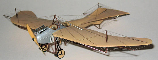 engine, which needs to be seated down on a small shelf in the front of the
fuselage.
The cowling needs to be
trimmed back for this, as the engine will eventually need exhaust stacks and one
water pipe assembly on the left side, and these will be difficult to fit unless
the cowling is trimmed down.
This
problem will become obvious when you get to this stage of the construction.
engine, which needs to be seated down on a small shelf in the front of the
fuselage.
The cowling needs to be
trimmed back for this, as the engine will eventually need exhaust stacks and one
water pipe assembly on the left side, and these will be difficult to fit unless
the cowling is trimmed down.
This
problem will become obvious when you get to this stage of the construction.
| COLORS & MARKINGS |
Once the
wings and tailplanes were installed, and
all seams were filled, it was time for painting.
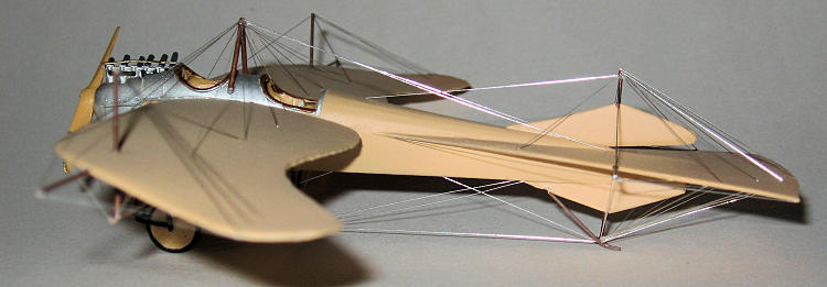
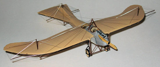
I used the kit instructions for reference, using silver for the cowling
and a beige fabric color for the rest of the airplane.
I masked off the engine and cockpit interior, so painting was an easy
task. Then the fun began.
| FINAL CONSTRUCTION |
 s,
and some of the “V” struts.
My
suggestion would be to attach all of the landing gear and underside
struts while the plane is laying on its back. I used a small rotating
table I have, so I could turn the plane around without handling it.
This plane is EXTREMELY delicate, and you don’t want to handle it any
more than absolutely necessary.
I’ll guarantee that it you handle it, you’ll break something.
Once the landing gear and tailskid are attached, you can turn the thing
over and test the structural integrity of the gear.
Don’t attach the upper struts, yet, however.
Wait on the prop, as it can be attached
last.
s,
and some of the “V” struts.
My
suggestion would be to attach all of the landing gear and underside
struts while the plane is laying on its back. I used a small rotating
table I have, so I could turn the plane around without handling it.
This plane is EXTREMELY delicate, and you don’t want to handle it any
more than absolutely necessary.
I’ll guarantee that it you handle it, you’ll break something.
Once the landing gear and tailskid are attached, you can turn the thing
over and test the structural integrity of the gear.
Don’t attach the upper struts, yet, however.
Wait on the prop, as it can be attached
last.
There are some three view drawings on
line that will be helpful.
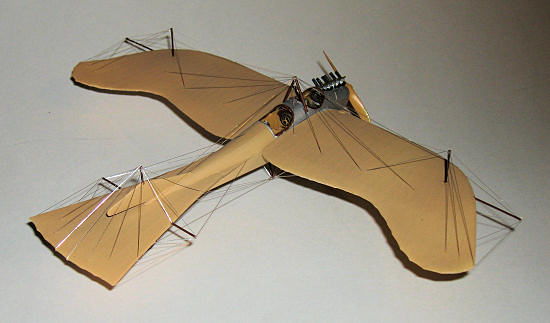
Just
about every conceivable part of this airplane is braced by at least one wire.
The box art four view drawing is also very helpful, and
it is complete enough that you shouldn’t really need any more
information. Again, place the airplane on its back without any upper struts
attached. I use stranded electronic wire, from which I strip the insulation. I
then roll the wire out on a flat surface until the wire is perfectly straight.
I measure the wire’s required length with a set of dividers, cut it to
size with a round bladed Xacto knife. Then handling the wire with tweezers, I
use a spot of white glue to attach the wire in the proper position.
I took approximately three hours to attach all of the rigging wires on
this model, and it certainly was a tedious process, but the effects are all out
of proportion to the effort involved.
Once all of the struts and rigging wire were in place on the bottom, I
CAREFULLY turned the model over on its gear, and attach any struts on the top.
Once these are in position, I cut and attached the wires on the upper
surfaces of the plane.
I also
attached the struts on the wingtips and tailplane, and then applied the wires in
their proper positions.
Gluing on
the prop was the final step, and the model was finally finished.
| CONCLUSIONS |
April 2012
If you would like your product reviewed fairly and quickly, please contact me or see other details in the Note to Contributors.