1/72 Blackburn Twin
| REVIEWER: | Stephen Foster |
| NOTES: | Scratch built. |
| HISTORY |
In 1915 the British Admiralty issued a specification for a long range Zeppelin interceptor which could operate over the sea at night. It was to be armed with Ranken incendiary steel darts which were to be dropped over the side of the aircraft which was expected to fly above the target.
 The Blackburn Aircraft Company was already building BE 2c
trainers and Sopwith Cuckoo torpedo bombers, but the T.B. or Twin Blackburn was
the first indigenous design to be submitted by the company. Construction was
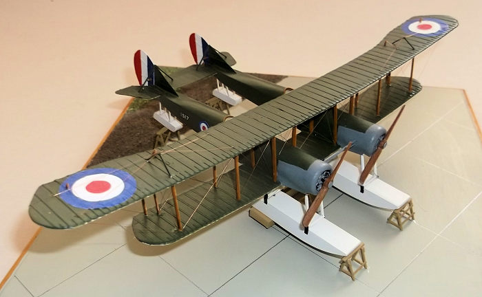
conventional box girder fuselages with a rotary engine at the front of each,
joined by a 10 foot centre section and common tail unit. The wings were three
bay with a large overhang and the fins and rudders were slightly modified BE 2c
units.
The Blackburn Aircraft Company was already building BE 2c
trainers and Sopwith Cuckoo torpedo bombers, but the T.B. or Twin Blackburn was
the first indigenous design to be submitted by the company. Construction was
conventional box girder fuselages with a rotary engine at the front of each,
joined by a 10 foot centre section and common tail unit. The wings were three
bay with a large overhang and the fins and rudders were slightly modified BE 2c
units.
The original intention was to power the aircraft with two 150hp Smith radial engines which offered a very low weight to power ratio and low fuel consumption. However production units did not prove to be reliable and so 100hp Gnome Monosoupape or 110hp Clergets were fitted instead. The resultant lower powered aircraft were in fact seriously underpowered and the performance of the aircraft fell far short of the operational requirements.
There were some other problems which made the type less than
optional too. When one of the early production types was being tested the flight
test observer recorded that while the pilot sat in one cockpit with all of the
controls, he sat in the other with just the engine starting handle. When the
Gnome engine was primed a pool of excess petrol formed on the float and ignited
when the engine was fired. The observer was expected to lie on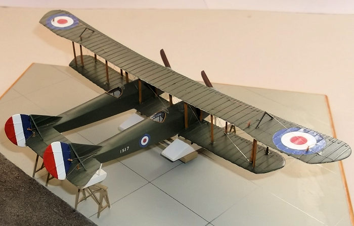 the lower centre
section and put out the fire on the pilot’s side with a fire extinguisher and
then climb into his own cockpit to start the second engine. The fire
extinguishing performance had to be repeated and then the observer could clamber
back into his own cockpit ready for take off.
the lower centre
section and put out the fire on the pilot’s side with a fire extinguisher and
then climb into his own cockpit to start the second engine. The fire
extinguishing performance had to be repeated and then the observer could clamber
back into his own cockpit ready for take off.
Once airborne the test pilot found that the mainplanes flexed to such a degree that all lateral control was lost. This was rectified by adding king posts and bracing to the wing overhangs, but then the relative movement between the fuselages caused the pilot further problems with stability and control. Communication between the crew was by hand signals which meant that co-ordinating any attack on an airship at night would be been close to impossible. The lack of power from the engines meant that the total offensive load was restricted to 70 lb and the rate of climb was such as to make it doubtful whether the aircraft would ever be able to intercept a target.
Although a total of 7 of the 9 aircraft built were sent to RNAS Killingholme they were hardly used and were eventually struck off charge, a fate shared by the two remaining aircraft which were never taken from storage.
| CONSTRUCTION |
I started as I do with most of my models by cutting out wing
blanks from 30 thou plastic card and adding ribs from 10 x 20 thou Evergreen
plastic strip. I use liquid glue to hold the ribs in place and when this has set
I gently sand the strip to reduce its thickness and round the edges. Holes were
drilled in the upper surfaces of the lower wing and under surfaces of the upper
wing to take struts later. The tail surfaces were made in the same way at the
same time. The fuselages were simple box structures of 30 thou plastic card
built around formers. I moulded the curved upper decking as separate units to
the front and rear of the cockpit openings a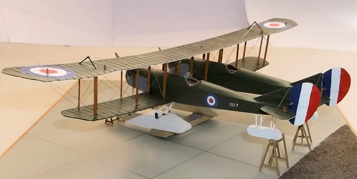 nd cemented these to the top of the
fuselage boxes. A little filler was used to clean up the joints. Seats were made
for both fuselages and controls in the port (left) fuselage only. The cowlings
were plunge moulded by sanding the end of a piece of dowel until it was the
correct diameter and making a hole in a piece of plywood which was the exact
outer diameter of the cowlings. I pinned a piece of 30 thou plastic card over
the hole, heated the plastic under a grill and used the end of the dowel to push
the softened plastic card through the hole. The engines were scratch built from
card and rod - they did not need too many details as they are barely visible
underneath the cowlings. I drilled a hole in a piece of card which I had glued
to the front ends of the fuselages, put a pin in the rear of the engines and
glued the engines into place after they had been painted and before I put the
cowlings on. The cowling to fuselage joint was also filled as necessary and
sanded down. Fins were glued to the rear ends of the fuselages.
nd cemented these to the top of the
fuselage boxes. A little filler was used to clean up the joints. Seats were made
for both fuselages and controls in the port (left) fuselage only. The cowlings
were plunge moulded by sanding the end of a piece of dowel until it was the
correct diameter and making a hole in a piece of plywood which was the exact
outer diameter of the cowlings. I pinned a piece of 30 thou plastic card over
the hole, heated the plastic under a grill and used the end of the dowel to push
the softened plastic card through the hole. The engines were scratch built from
card and rod - they did not need too many details as they are barely visible
underneath the cowlings. I drilled a hole in a piece of card which I had glued
to the front ends of the fuselages, put a pin in the rear of the engines and
glued the engines into place after they had been painted and before I put the
cowlings on. The cowling to fuselage joint was also filled as necessary and
sanded down. Fins were glued to the rear ends of the fuselages.
Attaching the fuselages to the lower wing was straightforward - I laid the lower wing on to a set of plans which I had copied from the internet and glued them into place, and when these had dried out fully I was able to fill and sand the joints to remove any irregularities. The floats were also made as box structures from 30 thou card: I inserted small pieces of scrap plastic on the sides of the floats so that when the upper and lower surfaces are joined they sit In the correct positions. The struts were cut and shaped from 20 x 30 thou plastic strip. The horizontal tail surfaces were added to the rear of the fuselages prior to painting.
| COLORS AND MARKINGS |
 I paint biplanes when the lower wing to fuselage joint has
been made as this makes the task much easier and quicker than if the top wing is
in place. The colours of these machines appears to have been PC10 upper
surfaces, clear doped linen undersides and dark grey cowlings and side panels
behind the engines. I used acrylics and mixed my own PC 10 from a mixture of
green and earth - the actual colour varied considerably according to age and
amount of exposure so an olive green shade was aimed for. The clear doped linen
was mixed from mainly white with a small amount of Revell Beige (314) mixed in
in an approximate ratio of 5:1. Individual modellers will decide what shade they
find acceptable. The struts were painted with Revell SM 382 enamel and the
floats and float struts were white. The markings were hand painted using
acrylics, and the serial came from a very old transfer sheet which I have in my
spares collection.
I paint biplanes when the lower wing to fuselage joint has
been made as this makes the task much easier and quicker than if the top wing is
in place. The colours of these machines appears to have been PC10 upper
surfaces, clear doped linen undersides and dark grey cowlings and side panels
behind the engines. I used acrylics and mixed my own PC 10 from a mixture of
green and earth - the actual colour varied considerably according to age and
amount of exposure so an olive green shade was aimed for. The clear doped linen
was mixed from mainly white with a small amount of Revell Beige (314) mixed in
in an approximate ratio of 5:1. Individual modellers will decide what shade they
find acceptable. The struts were painted with Revell SM 382 enamel and the
floats and float struts were white. The markings were hand painted using
acrylics, and the serial came from a very old transfer sheet which I have in my
spares collection.
| FINAL BITS |
Fitting the upper wing on biplanes can put a lot of people off
but provided that a systematic approach is adopted, the procedure can be
straightforward. I put the centre struts which are inboard of the fuselage
nacelles into the lower wing and while these were still soft I lowered the upper
wing on to them. I supported this structure with a simple jig made from square
paint pots ensuring that the wings were correctly aligned
 and the struts
vertical. When the struts were dry I added the two pairs of outer wing struts
and allowed these to set before putting in the remaining struts. The model was
then inverted and the tail floats glued into place and allowed to set fully. The
main floats followed and they too were allowed to set. Finally the king posts on
the upper wing and rudders on the tail completed this stage of the construction.
The model was rigged with 44 SWG rolled copper wire held with CA superglue.
Again provided that rigging is done systematically it should be straightforward.
I always start with the least accessible points and work outwards from there -
in this case the centre section was rigged first followed by the outer wing
bays, tail surfaces and finally control wires. The propellors were carved from
hardwood strip and fitted after the rigging was complete.
and the struts
vertical. When the struts were dry I added the two pairs of outer wing struts
and allowed these to set before putting in the remaining struts. The model was
then inverted and the tail floats glued into place and allowed to set fully. The
main floats followed and they too were allowed to set. Finally the king posts on
the upper wing and rudders on the tail completed this stage of the construction.
The model was rigged with 44 SWG rolled copper wire held with CA superglue.
Again provided that rigging is done systematically it should be straightforward.
I always start with the least accessible points and work outwards from there -
in this case the centre section was rigged first followed by the outer wing
bays, tail surfaces and finally control wires. The propellors were carved from
hardwood strip and fitted after the rigging was complete.
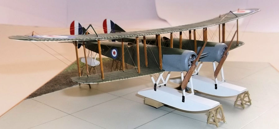
The photographs of this type show it on a large block of wood and small trestles under the main floats and trestles under the tail floats, on a concrete base with what appears to be a muddy track behind the aircraft. I tried to model this by using a small square of hardboard and simulating the grass verge and muddy track with plaster filler. The block of wood was made from laminated plastic card and trestles from plastic strip.
| CONCLUSIONS |
Models of early prototype aircraft are rare, which is not surprising as they are frequently little known: I had this particular type brought to my attention by a fellow modeller on a website. I have long had an interest in the weird and wonderful when it comes to flying machines, and enjoy the challenges that building early aircraft offer to the modeller. This aircraft therefore suited my interests for a number of reasons, but the chances of one being produced either as a vacuform or in resin are very small, so my only option was to scratch build one. Provided that the modeller can push mould some plastic this was not a difficult model to make but it does attract attention from others because of the unusual, not to write bizarre, design.
| REFERENCES |
Blackburn Aircraft Since 1909, A. J. Jackson, Putnam 1988.
There are a number of photographs, and drawings of the type on the internet.
18 August 2023
Copyright ModelingMadness.com. All rights reserved. No reproduction in part or in whole without express permission.
If you would like your product reviewed fairly and fairly quickly, please contact the editor or see other details in the Note to Contributors.