
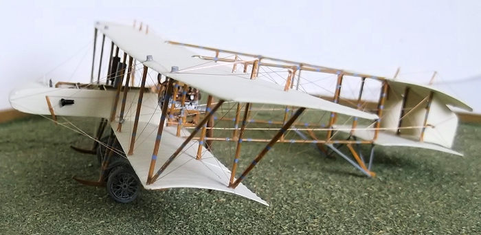
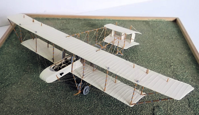
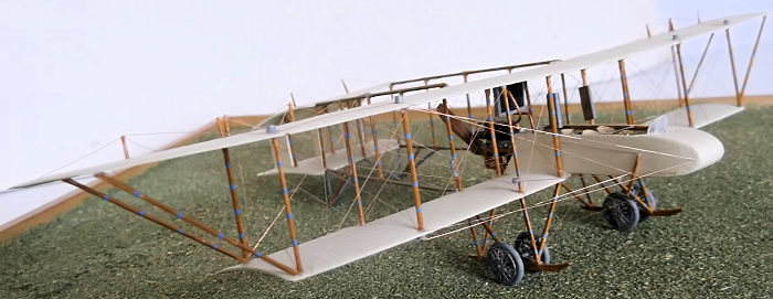
1/72 Grahame-White Type X 'Charabanc'
| KIT #: | |
| PRICE: | |
| DECALS: | |
| REVIEWER: | Stephen Foster |
| NOTES: | Scratchbuilt |
| HISTORY |
Claude Grahame-White founded an aeroplane manufacturing company at Hendon in 1911 to cover his interests in heavier-than-air flying machines. His importance to British aviation was considerable as he fostered interest in flying among the general public in Britain. He opened a flying school at Brooklands but moved it to Hendon where it became the busiest in Europe, holding regular weekly displays and races. His chief designer was John Dudley North who later became the chief designer for Boulton and Paul. White’s company produced a number of original, (and sometimes odd, not to say bizarre), biplanes, many of them pushers, of which the Type X was one. Part of the attraction of Hendon to the general public was the flying of passengers around the aerodrome. However most aircraft could only carry one or at most two passengers, and White saw an opportunity to meet extra demand by building a larger capacity aeroplane. The Type X was designed by J. D. North to carry 4 passengers in wicker seats behind the pilot and started to offer rides in September 1913. It was quickly dubbed the "Charabanc" by the public after the buses used to take holiday makers on day trips and outings to coastal resorts. It also had a very large silencer fitted to the exhaust and a klaxon on the port side of the nacelle which could be easily heard on the ground as the aircraft flew over the crowds.
 On 2nd
October a record was set when 9 passengers were carried for nearly 20 minutes:
later 10 passengers were taken aloft - a world record for a heavier-than-air
machine at the time. On 9 May 1914 W. Newall made the first jump from an
aeroplane in Britain using a parachute. Newell sat on a rope seat which had been
rigged between the front and diagonal struts on the port side of the
undercarriage, with his feet braced against the skid. He had the parachute on
his lap with a release cord in his hand. F. Goodden climbed out of the nacelle
when the aeroplane had reached 2000 feet and pushed Newell off his seat with his
foot! Other stunts carried out with this machine included having two people sit
on the lower wing tips holding on to the struts while it was in the air.
On 2nd
October a record was set when 9 passengers were carried for nearly 20 minutes:
later 10 passengers were taken aloft - a world record for a heavier-than-air
machine at the time. On 9 May 1914 W. Newall made the first jump from an
aeroplane in Britain using a parachute. Newell sat on a rope seat which had been
rigged between the front and diagonal struts on the port side of the
undercarriage, with his feet braced against the skid. He had the parachute on
his lap with a release cord in his hand. F. Goodden climbed out of the nacelle
when the aeroplane had reached 2000 feet and pushed Newell off his seat with his
foot! Other stunts carried out with this machine included having two people sit
on the lower wing tips holding on to the struts while it was in the air.
The machine was powered by a 120 hp Austro-Daimler engine, but prior to November 1913 this was replaced by a 100 hp Green engine so that the Charabanc could enter the all-British manufactured aircraft race - the Michelin Cup No 1, a 300 mile to and fro route between Hendon, north of London to Brooklands in Surrey, south west of London. The Charabanc won this competition. Grahame-White attempted a London-Paris flight but was forced to land at Folkestone with a fuel leak. The Royal Aero Club states that the machine was sold to the Japanese Navy in 1916.
The Charabanc was the largest aeroplane to be built in Britain prior to the outbreak of the First World War, and many modifications and changes were made when it was in service. The klaxon was removed and replaced by a long step to allow passengers easier access to the cockpit and a gravity tank was put under the top wing. The camber of the wings was very marked in order to increase the lift but this slowed the machine down to a speed of about 45 mph in the air.
 During
WW1 White’s company was contracted to build aircraft for the RNAS but in 1917 a
dispute arose over the quality of the workmanship. Due to shortages, low quality
wood was being delivered to the company and used in construction, so the
aircraft were rejected for use. From 1919 Grahame-White attempted to build large
commercial aircraft but without real success. The dispute with the government
over the failure to deliver aircraft during the war continued after the war had
ended and in 1921 the Admiralty took over the Hendon site in lieu of outstanding
debts. Hendon aerodrome was passed to the RAF and was the site for continued air
pageants during the interwar years. After the Second World War the airfield was
sold and became a housing estate, but the hangars and office buildings were
retained and now house part of the RAF museum collection.
During
WW1 White’s company was contracted to build aircraft for the RNAS but in 1917 a
dispute arose over the quality of the workmanship. Due to shortages, low quality
wood was being delivered to the company and used in construction, so the
aircraft were rejected for use. From 1919 Grahame-White attempted to build large
commercial aircraft but without real success. The dispute with the government
over the failure to deliver aircraft during the war continued after the war had
ended and in 1921 the Admiralty took over the Hendon site in lieu of outstanding
debts. Hendon aerodrome was passed to the RAF and was the site for continued air
pageants during the interwar years. After the Second World War the airfield was
sold and became a housing estate, but the hangars and office buildings were
retained and now house part of the RAF museum collection.
| CONSTRUCTION |
My first task was to find some drawings: fortunately Flight Magazine came up trumps: the drawings look a little crude but they have the dimensions on them which means that even if the outlines are not wholly accurate, the dimensions will be. There are also a large number of photographs which show that the machine changed in detail during its short life: as most of the photos are undated a little research was necessary to put them into some form of chronological order. I cannot argue that what I have produced is 100% accurate, but then nobody can prove otherwise - always an advantage when scratch building one of these rarer types!
I made the wings and tail surfaces from 30 thou
plastic card which had been bent in a pipe filled with hot water. The camber of
both wings and tail surfaces was quite marked as shown on the drawings and is
evident in the photographs. Ribs were added by gluing 10 x 20 thou Evergreen
strip to the upper surfaces and when dry sanding them down until they only just
protrude above the surface. Struts were cut and shaped from 30 x 40 thou
Evergreen strip. The fuselage nacelle was cut form 20 thou card: two sides and a
one piece bottom/nose. The latter was curved by sliding the plastic between the
blade of a pair of scissors and my thumb - in the same way as ribbon can be made
to curl. In order to keep the structure square I inserted some scrap plastic to
the joint between the fuselage floor and sides and braced the structure with
small squares of thick plast ic
card while the cement dried. The squares were removed later. The empty nacelle
was cemented to the lower wing after the internal structure and bracing had been
added and the interior painted. The cockpit is very open and visible so I added
rudder pedals, a wooden slatted floor, instrument bar, and fuel and oil tanks at
the rear. The seats were wicker on the original craft and Barracuda make some
excellent resin products which proved to be ideal for this project: indeed
arguably they made it a possibility as I would not wish to make 5 of these from
scratch. Cushions to spare the fare paying public from discomfort were made from
card. The remaining interior details were added to the nacelle.
ic
card while the cement dried. The squares were removed later. The empty nacelle
was cemented to the lower wing after the internal structure and bracing had been
added and the interior painted. The cockpit is very open and visible so I added
rudder pedals, a wooden slatted floor, instrument bar, and fuel and oil tanks at
the rear. The seats were wicker on the original craft and Barracuda make some
excellent resin products which proved to be ideal for this project: indeed
arguably they made it a possibility as I would not wish to make 5 of these from
scratch. Cushions to spare the fare paying public from discomfort were made from
card. The remaining interior details were added to the nacelle.
The engine that I chose to represent was the 120 hp Beardmore. This was quite a complex looking object but there are good scale drawings available and the WingnutWings website has lots of information. I was also fortunate to own a WNW kit of a Beardmore which I could refer to for some details. The sump was made from laminated card and the cylinders from rod. Pieces of strip and small lumps of laminated card became the different external features, with thin wire the pipes on the sides of the cylinders. The overhead valve gear was made from small scraps of plastic, and squares of plastic and short lengths of rod made the carburettors and inlet pipes. Close up the engine lacks the crispness of a white metal or resin product, but as nobody is ever going to be able to inspect it with a magnifying glass I am not too bothered. The exhaust was a large cylinder which helps to obscure one side side of the engine. A small frame was made from Evergreen strip and rigged with rolled 44 SWG copper wire - my go to material for rigging 1/72 scale biplanes.
| COLORS & MARKINGS |
 Scratch
building pusher types requires the modeller to paint many parts during the
construction processes. After the nacelle had been fixed to the lower wing I
painted that assembly and all the remaining flying surfaces clear doped linen.
The colour of CDL varied widely according to the type of material used, the age
and exposure of the linen to the elements, wear and much else. I use a mixture
of approximately 5 parts Revell matt white and two parts Revell Beige (314)
acrylics - the exact proportions do not matter: just experiment until you get a
shade that you think is close to the real thing. I do not use under shading to
show ribs etc on this scale of model as I think that the contrasts would be so
small as to be almost invisible except in strong through light. The engine was
painted in Revell acrylic aluminium (99), Humbrol copper enamel, and Revell
acrylic black. The exhaust was painted black and then dry brushed with dark grey
and rust. The engine frame and struts were painted with Revell SM 382 enamel and
the wicker seats a mixture of Revell acrylic Beige and Oker (88).
Scratch
building pusher types requires the modeller to paint many parts during the
construction processes. After the nacelle had been fixed to the lower wing I
painted that assembly and all the remaining flying surfaces clear doped linen.
The colour of CDL varied widely according to the type of material used, the age
and exposure of the linen to the elements, wear and much else. I use a mixture
of approximately 5 parts Revell matt white and two parts Revell Beige (314)
acrylics - the exact proportions do not matter: just experiment until you get a
shade that you think is close to the real thing. I do not use under shading to
show ribs etc on this scale of model as I think that the contrasts would be so
small as to be almost invisible except in strong through light. The engine was
painted in Revell acrylic aluminium (99), Humbrol copper enamel, and Revell
acrylic black. The exhaust was painted black and then dry brushed with dark grey
and rust. The engine frame and struts were painted with Revell SM 382 enamel and
the wicker seats a mixture of Revell acrylic Beige and Oker (88).
| FINAL CONSTRUCTION |
 The
engine, mounted in its frame, was cemented to the rear of the nacelle. It is
worth noting that the engine frame was carried above the rear of the lower wing
surface. The lower boom struts were made from florists wire and epoxied into
shallow grooves which had been filed into the upper rear surface of the lower
wing. The lower horizontal tail surface had two small slots cut into the leading
edge where the rear ends of the booms could be inserted and epoxied. The
sub-assembly was supported so that it matched the plan side profile. I placed
the wing on the desk and rested the tail surface on a piece of wood while the
epoxy cured. The upper horizontal flying surfaces and booms were joined in the
same way.
The
engine, mounted in its frame, was cemented to the rear of the nacelle. It is
worth noting that the engine frame was carried above the rear of the lower wing
surface. The lower boom struts were made from florists wire and epoxied into
shallow grooves which had been filed into the upper rear surface of the lower
wing. The lower horizontal tail surface had two small slots cut into the leading
edge where the rear ends of the booms could be inserted and epoxied. The
sub-assembly was supported so that it matched the plan side profile. I placed
the wing on the desk and rested the tail surface on a piece of wood while the
epoxy cured. The upper horizontal flying surfaces and booms were joined in the
same way.
Many modellers think that assembling biplanes without
a jig is almost impossible: assembling a pusher without one is impossible. I beg
to differ as most pushers did not have any wing stagger: the upper wing was
directly above the lower one. Having several pairs of struts is also not a
problem provided they are put into place in an ordered sequence. Simple supports
using Revell square acrylic paint pots and a little patience is all that was
needed to assemble this model. I started by cementing the four wing struts into
the lower wing around the nacelle and the two inner struts into the lower
horizontal tail surface. While the cement was setting I laid the upper wing on
the desk and placed small drops of cement into the holes where the wing and tail
struts were to be inserted. I inverted the nacelle/wing sub-assembly and lowered
the strut ends into the holes on the underside of the top wing - a small amount
of adjustment with a pair of tweezers was necessary but easily accomplished. Now
I placed 4 paint pots around the assembly - two to the rear of the wings and
touching the booms, and two in front of the wings touching the nacelle. These
held the structure and kept everything square while the cement set overnight. In
the morning I could place the model right side up and insert the four outer wing
struts and the outer front struts on the tail. To ma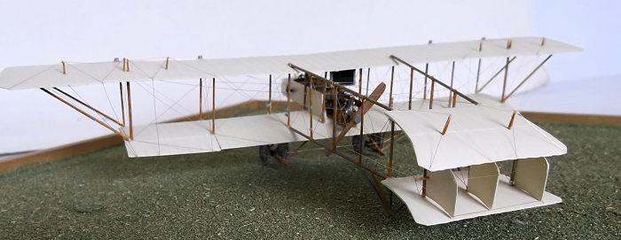 ke
sure that they were properly fixed I placed two pots of Humbrol enamel on the
top wing until the cement had set. I rigged the fore-aft struts next to the
nacelle and the centre of the tail, plus the front of the tail struts. This was
because they were easy to reach at this stage and were less at risk of being
damaged later. I now had a rigid structure into which I could add the remaining
wing and tail struts, starting with the inner wing struts and working outwards,
and then the tail units. I rigged the fore-aft wires between the wing struts and
the rear of the wing bays, again because of ease of access. The boom struts were
glued with superglue. The main undercarriage was constructed form Evergreen
strip and assembled one side at a time. The axles were wire cut from a paper
clip and the wheels made from discs of 60 thou card with 50 thou rod bent around
a small paint brush handle and held in hot water for the tyres. The tail skids
were made from similar material and assembled one side at a time. The control
horns, klaxon and propellor carved from wood were fitted and the remaining
rigging completed.
ke
sure that they were properly fixed I placed two pots of Humbrol enamel on the
top wing until the cement had set. I rigged the fore-aft struts next to the
nacelle and the centre of the tail, plus the front of the tail struts. This was
because they were easy to reach at this stage and were less at risk of being
damaged later. I now had a rigid structure into which I could add the remaining
wing and tail struts, starting with the inner wing struts and working outwards,
and then the tail units. I rigged the fore-aft wires between the wing struts and
the rear of the wing bays, again because of ease of access. The boom struts were
glued with superglue. The main undercarriage was constructed form Evergreen
strip and assembled one side at a time. The axles were wire cut from a paper
clip and the wheels made from discs of 60 thou card with 50 thou rod bent around
a small paint brush handle and held in hot water for the tyres. The tail skids
were made from similar material and assembled one side at a time. The control
horns, klaxon and propellor carved from wood were fitted and the remaining
rigging completed.
| CONCLUSIONS |
That was it - a one-off model of a one-off type which I knew nothing about until I saw a photograph on the net when researching another completely different aircraft. The joy of scratch building is that one can follow up these distractions and produce something different with a little effort and a low budget. I am interested in the early years of aviation but sadly there are very few kits of machines of this period so I have to build my own. However with a little practice there are not many parts which cannot be made and there are some good aftermarket parts which can make life a little easier along the way. Best of all the opportunities for making exotic and hardly known types is endless: give one a try.
| REFERENCES |
https://flyingmachines.ru/Site2/Crafts/Craft28796.htm
https://earlyaviators.com/egrahcl1.htm
3 February 2023
Copyright ModelingMadness.com. All rights reserved. No reproduction in part or in whole without express permission.
If you would like your product reviewed fairly and fairly quickly, please contact the editor or see other details in the Note to Contributors.