| KIT #: | |
| PRICE: | |
| DECALS: | |
| REVIEWER: | Chris Peachment |
| NOTES: | Lay in a vast store of plastic rod. |
| HISTORY |
I first came
across this strange and exotic beast while watching Those Magnificent Men in
their Flying Machines. Count Ponticelli, the Italian entrant in the air race
from London to Paris which forms the backdrop of the film, was constantly trying
out new machines. They were all designed by a character played in the film by
Tony Hancock, a popular British comedian at the time, noted for his gloomy
demeanour and eccentric opinions. In the film, he designs one aircraft which
unintentionally flies backwards, which was based on a real aircraft of the time,
the Dixon Nipper. He is last seen flying it backwards in the wrong
direction, towards Scotland rather than Paris, and
that Nipper, in a fetching red scheme, looks like a good candidate for a scratch
build at some time in the future.
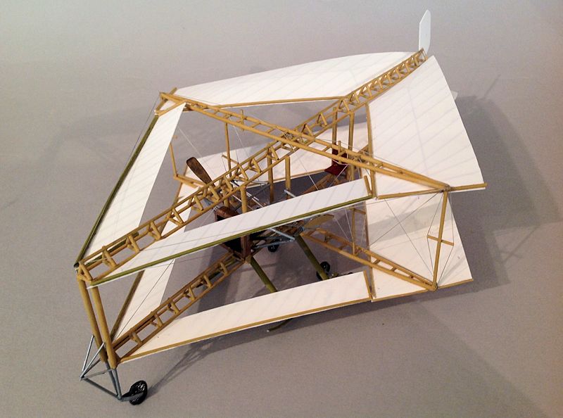
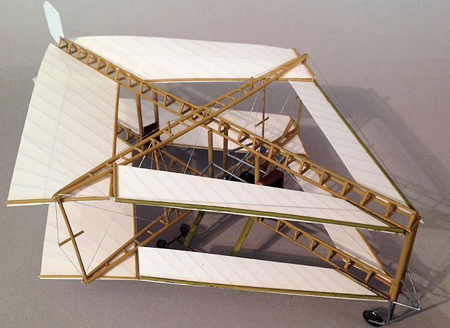
 The
Edwards Rhomboidal had annular biplane wings, of an immense 38 foot span,
arranged in rhomboidal or diamond pattern, with similar upper and lower
surfaces. The rear wings were three times the width or chord of the forward
wings. This strange arrangement came about after successful experiments with a
rubber powered model, presumably like the rubber band driven flying models that
aeromodellers still make.
The
Edwards Rhomboidal had annular biplane wings, of an immense 38 foot span,
arranged in rhomboidal or diamond pattern, with similar upper and lower
surfaces. The rear wings were three times the width or chord of the forward
wings. This strange arrangement came about after successful experiments with a
rubber powered model, presumably like the rubber band driven flying models that
aeromodellers still make.
In fact there is
no reason why this layout shouldn't work well. German scientists at the end of
WWII were working on forward swept wings, which solve the problem of achieving
high speed flight with good low speed handling. The main problems they
encountered were the extreme torsional forces on the wing spar. Since the
Edwards Rhomboidal had a top speed measured in miles per day, rather than MPH, I
do not think it would have mattered very much that the main wings were swept
forward. And while it is a very large beast by contemporary standards, it
would be immensely strong with all that cross bracing.
The large
structure of the aircraft was formed by a pair of triangular section wire-braced
trusses, rather like the box section girders that bridge builders use.
They would have made for a strong structure, being 48 feet long, albeit with
quite a weight penalty. These were vertically connected by thick round
struts.
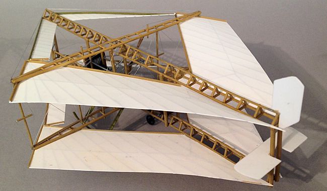
Each girder bore
a pair of flexibly mounted struts extending outwards, the wings being
tensioned between the ends of the longitudinal girders and the outer ends of the
struts by means of cables which formed the wing leading edges. The trailing
edges were under less tension, the intention being that the wings would deform
in flight and spread the wing load.
In the film, a
replica was made which was not airworthy, and so the brief sequence showing it
flying must have been created by suspending the replica from wires. The wings
are seen flapping around like flags in a high wind, and it doesn't look remotely
airworthy. In fact the linen of each wing was braced internally by
 chord-wise
struts sewn into pockets inside the linen, and so it seems unlikely that quite
so much slack was allowed to the wing surfaces on the original.
chord-wise
struts sewn into pockets inside the linen, and so it seems unlikely that quite
so much slack was allowed to the wing surfaces on the original.
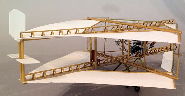
A rectangular
elevator was mounted on the rearmost connecting struts, and a small rudder,
above the upper wing. There were no ailerons or wing warping devices, and so
lateral control would have been difficult, and any turns would have been flat
rather than banked. A Humber water-cooled engine drove two propellers
between the wings by chains. The pilot sat well to the rear behind the engine,
presumably to counterbalance the weight of the engine and radiator.
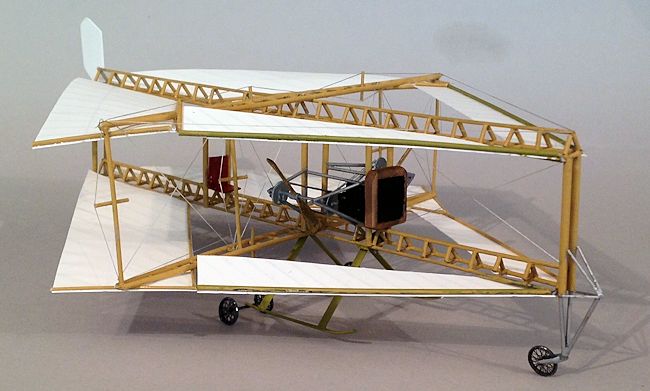
The undercarriage
was a pair of skids each bearing a pair of spoked wheels, with a castoring nose
wheel. It was tested at Brooklands aerodrome in 1911, but whether it actually
flew is unknown.
| CONSTRUCTION |
Scale plans can
be found on one of the websites below, although they are sketchy and it is wise
to print out as many photos as you can, and refer to them constantly.
 I began
with the structure, which one can hardly call a fuselage. The two main trusses
were made out of plastic rod, which I pinned to a sheet of balsa wood for
handling. The construction is simple though time consuming, and should be
familiar to anyone who ever made a balsa flying aircraft kit. The two wing
support girders can be made at the same time, though note that they are
bow-shaped and meet at each end. A few cross bracing struts were added here and
there, and rigged as in the pictures.
I began
with the structure, which one can hardly call a fuselage. The two main trusses
were made out of plastic rod, which I pinned to a sheet of balsa wood for
handling. The construction is simple though time consuming, and should be
familiar to anyone who ever made a balsa flying aircraft kit. The two wing
support girders can be made at the same time, though note that they are
bow-shaped and meet at each end. A few cross bracing struts were added here and
there, and rigged as in the pictures.
The main trusses
were joined with thick rod, and then the wing supports can be glued to the main
trusses. The whole was given a coat of wood paint, for which I used Lifecolour
Mid Stone from the UK range.
The wings were
then cut to plan from 5 thou plastic card, and ribs were scored underneath using
a steel rule and black biro. Leading edge struts were added from rod, but the
trailing edges left unsupported. The scoring automatically left the wings curved
and I left them like that to simulate the wind getting underneath them. The
original had bracing wires under the trailing edges, but not under great tension
to allow free movement in the wind.
The most
complicated part was the engine and propeller module, which I made from lengths
of rod surrounding an old inline four engine I had in the Bag of Engines in
spares box. A prop shaft was added b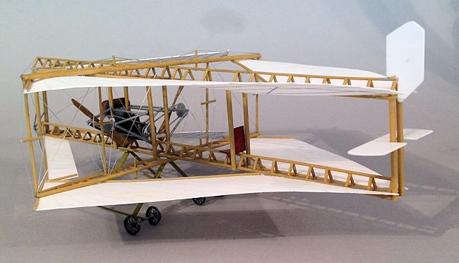 ehind
the engine, (prop shaft as in car, not as in aircraft) with two discs of plastic
to represent cogs. Propellers are wide and fan shaped, and were cut down from an
old Corsair prop I had in the spares box. Each blade was mounted on some plastic
tube and threaded on a rod which fitted into the structure. Together with two
discs to represent the prop cogs. Thin rod represents the drive chains.
ehind
the engine, (prop shaft as in car, not as in aircraft) with two discs of plastic
to represent cogs. Propellers are wide and fan shaped, and were cut down from an
old Corsair prop I had in the spares box. Each blade was mounted on some plastic
tube and threaded on a rod which fitted into the structure. Together with two
discs to represent the prop cogs. Thin rod represents the drive chains.
An old car
radiator was cut down from something which had long since gone to the junkyard
in the sky. I suspect it might have been an old Airfix 1911 Rolls Royce since it
has that classic Gothic shape. You could as easily scratch one from scored card.
A seat was fashioned out of two slabs of card with a little putty for cushions.
The tailplanes were thin card, scored for the ribs.
Finally the
undercarriage was made from strut and rod and two axles mounted at the rear of
each skid, with two pairs of Eduard etched WWI spoked wheels. The tires were
made first from solder wrapped around a thick pencil. The front end was simply
more rod.
Simple, I thought, we will simply remove the nose cone and pack it with lead shot. Alas, a moment's scrutiny revealed it has no nose cone. In fact the whole aircraft is so devoid of skinning it is transparent. So the radiator came off, and the rear surface was lined with small slabs of lead sheet. That did the trick, though don't overdo it or the whole vast beast with become knock kneed, and sink onto its belly, like a dying dinosaur.
| CONCLUSIONS |
This should be
well within the bounds of anyone who has done a little scratch building and it
might even make a good starting kit. Construction was time consuming rather than
complicated. And there are no compound curves to worry about. I suspect the
original was put together by a blacksmith and a cabinet maker, and wouldn't have
presented either with any great challenges.
| REFERENCES |
http://www.impdb.org/index.php?title=File:ThoseMagnifient74.jpg
http://flyingmachines.ru/Site2/Crafts/Craft28410.htm
http://celticowboy.com/Round%20Aircraft%20Designs.htm
http://www.j2mcl-planeurs.net/dbj2mcl/planeurs-machines/planeur-fiche_0int.php?code=2394
http://www.picssr.com/photos/27862259@N02/page719
Chris Peachment
August 2014
If you would like your product reviewed fairly and fairly quickly, please contact the editor or see other details in the Note to Contributors.