| KIT #: | 32074 |
| PRICE: | $79.00 SRP |
| DECALS: | Six options |
| REVIEWER: | Otis Goodin |
| NOTES: | Outstanding kit. Worth the wait |
| HISTORY |
The Sopwith Camel was one of the iconic fighter aircraft of WWI, and probably its most famous. Even the casual observer of WWI aircraft is familiar with the name, it being used in various media to represent the classic WWI fighter. From books to movies to cartoons, the Sopwith Camel seems to be the aircraft of choice for Allied protagonists.
Development of the Camel, so named for the “hump” over its guns, commenced in
1916 as Sopwith was seeking to replace its highly successful but single gun Pup
with a more powerful, heavier armed aircraft. The initial Camel prototype
featured a single piece top wing with no dihedral, two Vickers machine guns, and
a 110hp Clerget engine. Combined with 5” dihedral bottom wings and a high center
of gravity, the Camel proved to be highly maneuverable but tricky and somewhat
dangerous to fly. The aircraft was further refined during development with a
variety of improvements including a 3-piece top wing with a center cut out for
better visibility and a more powerful 130hp Clerget engine. Production began in
earnest in January 1917 and the aircraft began appearing in service around May
of that year. The Camel was used by both the RFC and the RNAS, and each branch
of service adopted their preferred variants. The RNAS preferred the 1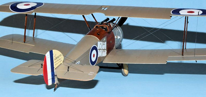 50hp
Bentley Rotary (BR 1) engine, while the RFC preferred either the LeRhone or
improved versions of the Clerget. However, both the Bentley and Clerget powered
aircraft developed problems with the interrupter gear while the LeRhone powered
aircraft, featuring the Constantinesco synchronizer, were much more dependable.
50hp
Bentley Rotary (BR 1) engine, while the RFC preferred either the LeRhone or
improved versions of the Clerget. However, both the Bentley and Clerget powered
aircraft developed problems with the interrupter gear while the LeRhone powered
aircraft, featuring the Constantinesco synchronizer, were much more dependable.
By war’s end around 5500 Camels were built by Sopwith and several licensees. Camels also saw service as a shipboard version with shorter wings, and as a night-fighter. In addition to Great Britain, Camels were used by Belgium, the United States, Canada, Estonia and Latvia. Interestingly, a number of the most successful aces were from Canada including William Barker, Raymond Collishaw, Donald McLaren and A. Roy Brown. With the appearance of the Snipe in 1918 the diminutive Camel’s days were numbered although the aircraft was not officially declared obsolete until 1919.
| THE KIT |
Wingnut
Wings released the long awaited Camel kit in February 2017, releasing not
one, but six, Camel kits at the same time. Among the variants were the BR 1,
LeRhone, USAS, Ship’s Camel, Clerget, and a Duellists version consisting of
a Camel paired with an LVG. The aircraft featured in this article is from
the Clerget version which contains parts and decals allowing the modeler to
build one of six separate aircraft: (1) Sopwith Camel B3889 flown by CF
Collett (11 victories), (2) Camel B3893 flown by A. Roy Brown (although no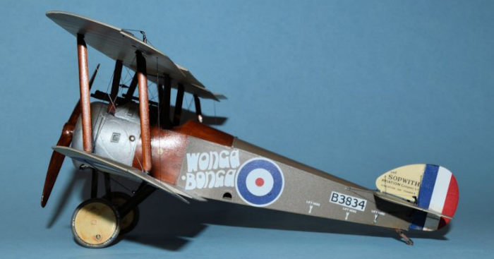 t
the Camel he was flying when Richthofen was shot down in April 1918), (3)
Camel B6289 flown by HL Nelson and WM Alexander of the RNAS, (4) Sopwith
Camel B6313 flown by Canadian ace Wm. Barker (50 victories), (5) Camel B7406
flown by HG Watson of the Australian Flying Corps in 1918, and, (6) the kit
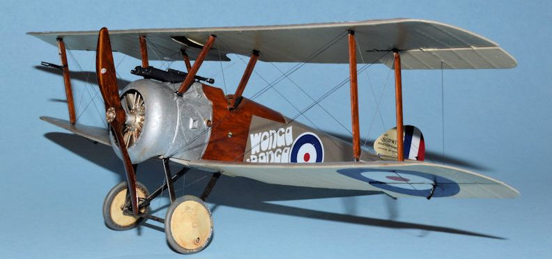
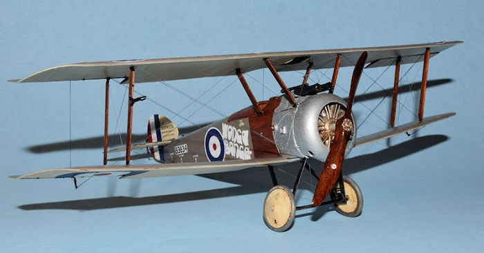
shown here, B3834 “Wonga Bonga” flown by RH Daly and AF Brandon of the RNAS
in the summer of 1917. The “Wonga Bonga” name is a nickname for “Gotha
Smasher” with “Wonga” meaning Gotha because of its distinctive engine sound
and “Bonga” meaning Smasher.
t
the Camel he was flying when Richthofen was shot down in April 1918), (3)
Camel B6289 flown by HL Nelson and WM Alexander of the RNAS, (4) Sopwith
Camel B6313 flown by Canadian ace Wm. Barker (50 victories), (5) Camel B7406
flown by HG Watson of the Australian Flying Corps in 1918, and, (6) the kit
shown here, B3834 “Wonga Bonga” flown by RH Daly and AF Brandon of the RNAS
in the summer of 1917. The “Wonga Bonga” name is a nickname for “Gotha
Smasher” with “Wonga” meaning Gotha because of its distinctive engine sound
and “Bonga” meaning Smasher.
The kit consists of 166 parts spread over 5 sprues including a clear parts sprue, a photo etch panel containing seat belts and machine gun parts, and a comprehensive decal sheet from Cartograf with decals for the six aircraft and the cockpit. The instructions are contained in the typical Wingnut full color glossy booklet of 22 pages, and contain not only instructions but numerous reference photos and material, including some of the Camel built by The Vintage Aviator, Ltd., a Peter Jackson company.
| CONSTRUCTION |
Construction begins in the highly detailed cockpit, starting with assembly of the ammo magazines and back engine plate. Following this the instrument panel and carburetor induction pipes are added, along with some panel details and decals. This is attached to the port fuselage frame along with the bent undershield to which the rudder bar has been added. Next the control column is attached to the floor boards, and the seat belts are added to the wicker seat. For the seat belts I used HGW laser cut fabric seat belts made specifically for the WNW Camel. I have used these before on the Fokker Eindecker and find them excellent and easier to work with than photo etch belts. Following this the seat and gasoline tank are added to the rear floorboard and these are joined to the port fuselage frame. If you plan to rig the cockpit you would begin this process now. There are numerous lines running along the floorboard as well as “X” wiring in the frames to complete. Unfortunately, because of the ultimate position of the cockpit underneath the top wing much of the cockpit detail is not that visible. However purists will want to rig the cockpit to have as complete a model as possible.
The starboard fuselage frame is then added to the assembly. The cabane struts
are molded onto both frames, presumably to make their installation easier and
more accurate. However, care should be taken in handling the assembled unit as I
inadvertently broke off both of the rear cabane struts. After reattaching them
and breaking them again I left them off until after the top wing was installed.
Not the ideal way to handle this but I made it work. Finally, the Vickers
machine gun subassembly was installed into the cockpit which
 consisted of the
rear half of the guns, an oil tank, empty shell chutes and gun mounts. The gun
barrels are installed later.
consisted of the
rear half of the guns, an oil tank, empty shell chutes and gun mounts. The gun
barrels are installed later.
Attention is next turned to the fuselage halves. There are various rigging lines to install in the tail skid area, and holes to drill in the fuselage depending on the aircraft you are building. The cockpit assembly is then installed in the starboard fuselage half along with the tailskid, then the port fuselage half is joined to the assembly. Finally the front engine plate is attached and the fuselage assembly is ready to be puttied and sanded. Fit was good and I only had to putty it twice to fill the minor gaps.
Next up the bottom wing and tailplane are added to the fuselage. You can choose to add the tailplane control horns now or wait until you are closer to rigging before adding them. I added mine now but I knocked them off several times during construction so next time I’ll wait. You could choose to separate the tailplane from its flaps and reposition them, although I chose not to this go around. The cockpit decking is next and depending on which aircraft you are building parts of the decking are removed prior to attaching it to the fuselage. The top cowling, or “hump,” is then added last.
Details are added to the fuselage/bottom wing assembly. The Camel, as did several British aircraft, has small windows in the wings to allow observation and adjustment of the aileron control lines. These windows are added from the clear parts sprue using clear parts cement. Depending on the version you are building the windows are outlined in either aluminum or dope color (PC 10 or 12). Be sure to cover the windows with tape once added to keep them from getting scratched or painted over. The fin and rudder assembly is then added to the rear of the fuselage. Don’t forget to add the control horn prior to attaching it. The instructions call for you to add the gun barrels and windscreen but I chose not to until after some painting was done. (I ultimately forgot the windscreen and was unable to install it with the top wing in place). There are various windscreen options depending on the particular aircraft. Versions B and E add the Rotherham petrol pump to the starboard front cabane strut, but it was not used on the version I built. Finally, before adding the top wing be sure to install the Aldis gun sight as it is very difficult to do once the wing is on.
The next step was to assemble the top wing. Like the original, the wing is
composed of three pieces, a center section and left and right sections. I glued
the three pieces together, let them dry flat on the work table, then lightly
puttied the sections to eliminate any major gaps. I left off the ailerons and
control horns until I was ready for rigging. Following this I was ready to add
the struts and attach the top wing. I normally add the wing to the cabane struts
and, once dry, then add the interplane struts separately. However, since I had
broken the two rear cabane struts I decided to install all the wing struts, then
install the wing, and finally reinstall the broken cabane s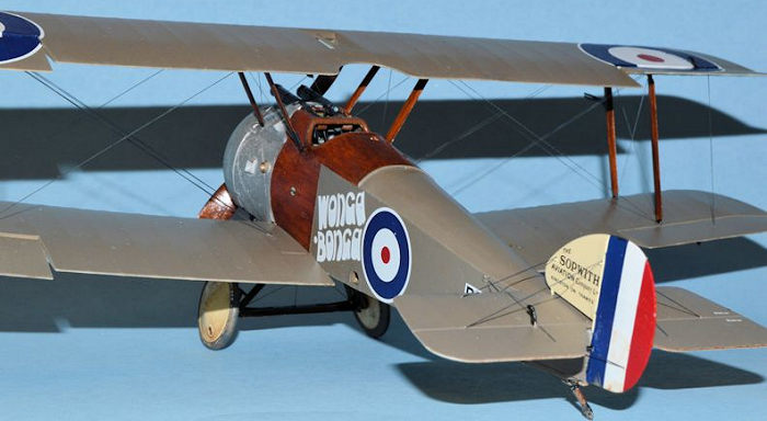 truts. Conceptually
this worked except the bottom dihedral meant that I needed to glue the top wing
to the struts on one side then hold the wing and struts on that side in place
until set before moving on to the other side. After holding the wing and struts
in place for about 5 minutes I was able to use some tape to continue holding
that side while I went to work on the other side. I glued the wing and struts on
the other side, held it in place for about 5 minutes, then used some more tape
to hold the wing and struts in place until it had set overnight. The next day I
added the rear cabane struts to the assembly, using a little super glue to fill
the gaps. I did a little touch up painting and the struts were almost like
they’d never broken. But next time I’ll try to be more careful.
truts. Conceptually
this worked except the bottom dihedral meant that I needed to glue the top wing
to the struts on one side then hold the wing and struts on that side in place
until set before moving on to the other side. After holding the wing and struts
in place for about 5 minutes I was able to use some tape to continue holding
that side while I went to work on the other side. I glued the wing and struts on
the other side, held it in place for about 5 minutes, then used some more tape
to hold the wing and struts in place until it had set overnight. The next day I
added the rear cabane struts to the assembly, using a little super glue to fill
the gaps. I did a little touch up painting and the struts were almost like
they’d never broken. But next time I’ll try to be more careful.
I decided to do most of the rigging now so I began by concentrating on the wings, installing the flying wires (the double wires leading from the top wing interplane struts to the lower wing next to the fuselage) first . WNW recommends the use of EZLine without turnbuckles since Camels didn’t have them anyway. EZ Line is easy to use, although a little “wiggly.” I used the fine size, 0.15mm, although I think the heavy grade 0.30 would have been better. Photos of Camels show the wing wires as quite thick. Regardless, I proceeded with the rigging by first drilling out dual location holes under the upper wing next to the interplane struts with an 80 bit in a pin vise. WNW recommends drilling the holes to a depth of 1mm. My reaction to this bit of advice was “uh, sure, let me get my metric ruler.” Seriously, just drill the holes to a comfortable depth making sure you don’t go all the way through the wing. You’ll probably be close to 1mm anyway. Once the location holes are drilled simply put a very small drop of super glue in one hole and place the end of the line in the hole, holding it with some tweezers until set (about 15-30 seconds). I typically work from inside out. Once the line is set then lightly stretch it to the location hole on the bottom wing and cut off enough EZ Line so that it doesn’t quite reach the intended location. Put a tiny drop of super glue in the hole and hold it in place with tweezers until set up. Make sure not to cut the line too short so that it has to stretch too much to reach the location because this puts too much tension on the line and makes it difficult for the super glue to set and hold the line. Trial and error will give you the experience to determine the right length to make the line. EZ Line will not sag with only a little bit of tension in the line so no need to make it too tight.
Once the flying wires were installed I then turned my attention to the landing wires, these being the single wires that run from the upper wing next to the cabane struts to the lower wing next to the interplane struts. I used the same technique for attaching these lines, then proceeded to install the X wires between the interplane struts and the cabane struts. In both cases the struts come with small location holes, or eyelets, on the struts through which to attach the X rigging wires. Before installing the struts, I made sure to drill out the holes with an 80 bit, very carefully, because the eyelets get filled with Future or paint. I would then thread the line through the top location eyelet and secure it with a drop of super glue. Once dry I would thread the other end through the lower eyelet on the other strut and secure it with super glue. Once dry I would trim off any excess line. Normally I would install all the lines in the top holes before moving on to the lower hole, but there’s no magic to it.
Rigging the teardrop shaped tensioner between the front cabane struts is
slightly tricky but don’t overthink it. Simply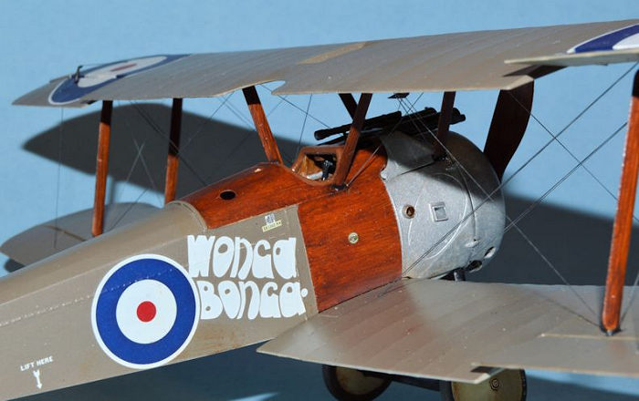 add the rigging to the tensioner
at the location points using EZ Line. Then cut the top EZ Lines to equal lengths
and secure the top two lines to the underside of the upper wing right next to
the cabane struts. There is a small indentation in the wing marking the
location. Once this is secure then thread the lower lines through the small
eyelets on the outer edge of the cabane struts, stretch them a bit to get the
tensioner in place, and secure them with super glue. I only had to redo my
tensioner rigging once. You may want to install the tensioner rigging prior to
installing the hump above the cowling because it makes it easier to reach the
eyelets on the cabane struts.
add the rigging to the tensioner
at the location points using EZ Line. Then cut the top EZ Lines to equal lengths
and secure the top two lines to the underside of the upper wing right next to
the cabane struts. There is a small indentation in the wing marking the
location. Once this is secure then thread the lower lines through the small
eyelets on the outer edge of the cabane struts, stretch them a bit to get the
tensioner in place, and secure them with super glue. I only had to redo my
tensioner rigging once. You may want to install the tensioner rigging prior to
installing the hump above the cowling because it makes it easier to reach the
eyelets on the cabane struts.
Once I was finished with all the internal wing rigging I moved on to attaching and rigging the ailerons. Rigging proceeded from the top wing to the control horn through the ailerons to the bottom control horn. From there I attached a separate line from the lower wing location back to the lower aileron control horn. All the locations are clearly marked beforehand so it just requires drilling out the location holes prior to rigging. After finishing both sides, I then moved on to rigging the tail section. The Camel has one of the most elaborately rigged tail sections I have ever seen. There are twenty-two separate lines required to rig the tail section, plus two more to rig the tail skid. It’s not difficult, but it does require some planning and patient execution. WNW gives good rigging diagrams although I recommend reading it several times before installing the lines.
After about three nights spent rigging the Camel I moved on to the undercarriage assembly and installation. The undercarriage consists of eleven parts including the struts (check your version to make sure you have the right ones), axle, spacers between the axle and the wheels, connectors to hold the wheels in place yet allow them to rotate, and the outer wheel covers. The spacers, also present on the real plane, serve to position the wheels so that the top part leans in a bit and the bottom part leans out. In other words, the wheels sit in a “splayed out” position rather than perfectly vertical. I’m not sure the reason for this unless it has something to do with stability. The entire undercarriage fits securely into location holes underneath the fuselage so it is possible to entirely assemble it, wheels and all, before installation. I didn’t do this, because I wanted to give myself some room for rigging, but it is an option.
Somewhere in this process I decided to attach the engine and cowling, after which I installed the machine gun barrels and photo etch parts. The engine is simple to assemble being a rotary engine with a few pushrods and induction pipes. The instructions call for some minor rigging to the spark plugs but it doesn’t show once the cowling is installed. Take care in attaching the cowling to the fuselage, as there are locking clips on the fuselage front that break off easily and are difficult to replace in the correct location once broken. I found the cowling somewhat of a challenge to attach because I had small gaps in various points around it after gluing that I then had to fill with super glue and paint over. I’m sure I did something wrong in the initial attachment of the firewall to the fuselage.
Once the cowling is installed the propeller is next. There are two props provided depending on the version you are building. Once my cowling was installed my engine would not turn inside it so I just placed the propeller on the engine shaft and turn it if needed to reposition it. Builder error I’m sure.
| COLORS & MARKINGS |
Painting follows along with the construction process so I began with
the cockpit interior first. The wood framing, cabane struts, instrument panel
and floor boards were all painted to look like wood, with the floor boards a
slightly lighter shade. I accomplished this by first painting the pieces with
Model Master Tan then, once dry, applying a glaze of slightly thinned Griffin’s
Burnt Umber. I applied one glaze to the floor boards and t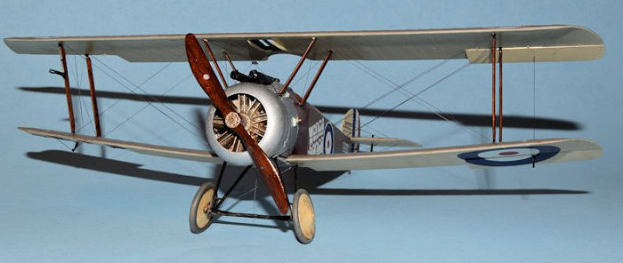 wo or more to
everything else. Once the glaze was dry I gave it a coat of Future by hand to
protect and seal the finish. I painted the wicker seat similarly, although I
wiped off much of the glaze but leaving enough to fill in the “holes” in the
wicker. The seat cushion was painted with MM Leather then a wash of Griffin’s
Burnt Umber was applied. The seat belts were also given a wash of thinned Burnt
Umber. The control column, ammo magazines, bent undershield and carburetor
induction pipes were all painted MM Aluminum. The instrument panel was detailed
by painting the instrument dials Gun Metal then applying instrument dial decals
to the faces. Additional decals were applied to the panel and a few control
knobs and buttons were painted Brass. Future was applied to simulate glass
covers on the instruments. Finally the rudder control bar was painted light wood
like the floor boards.
wo or more to
everything else. Once the glaze was dry I gave it a coat of Future by hand to
protect and seal the finish. I painted the wicker seat similarly, although I
wiped off much of the glaze but leaving enough to fill in the “holes” in the
wicker. The seat cushion was painted with MM Leather then a wash of Griffin’s
Burnt Umber was applied. The seat belts were also given a wash of thinned Burnt
Umber. The control column, ammo magazines, bent undershield and carburetor
induction pipes were all painted MM Aluminum. The instrument panel was detailed
by painting the instrument dials Gun Metal then applying instrument dial decals
to the faces. Additional decals were applied to the panel and a few control
knobs and buttons were painted Brass. Future was applied to simulate glass
covers on the instruments. Finally the rudder control bar was painted light wood
like the floor boards.
I painted the 30 gallon petrol tank that sits directly behind the seat Schwarzgrun with a brass tank cap. Various components within the cockpit framing were painted as indicated in the instructions: copper for various wires, aluminum and brass for the throttle control handle, and the various metal fittings on the frame and the cabane struts were painted Gun Metal.
The fuselage fabric interior was painted RFC Clear Doped Linen from Misterkit. The wooden section of the interior was painted light wood using MM Tan and Griffin’s Burnt Umber. The interior of the metal cowling was painted Aluminum. The tail skid was given the dark wood treatment with the brackets painted black. The exterior of the fuselage was painted using a multi-step process. I first painted the wooden section of the fuselage with MM Tan and then gave it a Burnt Umber glaze followed by a Burnt Sienna glaze to give it a reddish tone. Once dry I applied a few coats of Future by hand to seal and protect the finish. Afterward I then masked off the wooden section with Tamiya tape and painted the cowling surface with MM Aluminum Acrylic. Later I came back over it with MM Silver Chrome painted in irregular squiggles to give the cowling a “turned finish” look. I then painted the upper fabric surfaces of the fuselage with Misterkit Acrylic RFC PC12, and the bottom Misterkit RFC Clear Doped Linen. Once everything was dry I removed the masking tape, made a few touch ups and sealed the fuselage with Future.
The upper surfaces of the wings and tailplane were all painted PC12
and the under surfaces Clear Doped Linen. The tailfin was painted Clear Doped as
well. All the interplane struts were given the dark wood treatment wit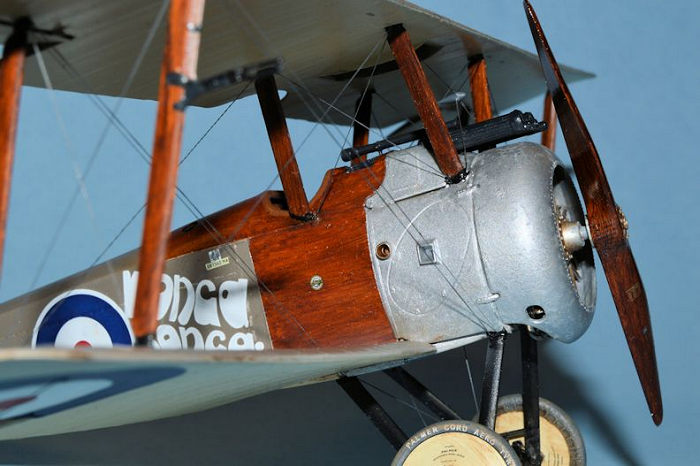 h MM Tan
and Burnt Umber with the brackets painted black. The machine guns were painted
MM Gun Metal, then drybrushed with a little Metallic Gray from Tamiya. The
various control horns throughout were painted MM Gloss Black, as were the
undercarriage struts and axle. The wheel covers are Clear Doped Linen and the
tires are Schwarzgrau, highlighted with a little Tamiya Buff.
h MM Tan
and Burnt Umber with the brackets painted black. The machine guns were painted
MM Gun Metal, then drybrushed with a little Metallic Gray from Tamiya. The
various control horns throughout were painted MM Gloss Black, as were the
undercarriage struts and axle. The wheel covers are Clear Doped Linen and the
tires are Schwarzgrau, highlighted with a little Tamiya Buff.
The rotary engine was painted MM Steel, the push rods and induction pipes Aluminum. Then the whole engine was given a wash of thinned Burnt Umber to represent burned castor oil.
The whole aircraft was given several sprays of Future to provide a glossy surface for the decals. With a few exceptions the decals went on with no problem. After application the decals were given another coat of Future, and then the glossy finish was toned down a bit with Polly Scale Satin finish. Thinned Burnt Umber was applied to the bent undershield, the undercarriage and along the fuselage bottom as burned castor oil and for general weathering. Finally the propeller was painted with the dark wood combination, then given a few coats of Future, decals applied and another coat of Future added. Finally, after several weeks, the Camel was completed.
| CONCLUSIONS |
The Sopwith Camel is another superb kit from Wingnut Wings. With six kit options every WWI enthusiast has plenty to pick from for their collection. There are a few idiosyncrasies with this kit that I will be better prepared to handle the next time I build one. However, I greatly enjoyed the process and am happy to have a finished Camel on my shelf.
| REFERENCES |
Sopwith Camel Squadrons, Les Rogers, Albatros Publications.
Wingnut Wings kit instructions.
Sopwith Camel, Wikipedia.
Copyright ModelingMadness.com
If you would like your product reviewed fairly and fairly quickly, please contact the editor or see other details in the Note to Contributors.
Back to the Main Page Back to the Review Index Page Back to the Previews Index Page