| KIT #: | F-163 |
| PRICE: | $ |
| DECALS: | One option |
| REVIEWER: | Stephen Foster |
| NOTES: | Eastern Express boxing |
| HISTORY |
The Vickers F. B. 27
Vimy is probably one of the better-known of the heavy bombers which was in RAF
service during the interwar years. This fame is due more to the exploits of this
aircraft in civilian guise than to the unglamorous service it gave in the RAF.
The Vimy was originally
designed and built as a replacement for the Handley Page 0/400 bombers which saw
active service in 1917 and 1918. The first prototype Vimy flew on November 30,
1917, but it took another 11 months before the RAF took delivery of its first
machines. On November the 11th 1918 only three had been accepted and none of
these was used operationally during the war. The cessation of hostilities in
Europe meant that the large wartime contracts for the Vimy were cancelled and
the RAF itself was subject to severe cutbacks in its operational strength. Thus
the introduction of this new aircraft into service was a somewhat prolonged
affair - 58 Squadron in Egypt being the first unit to equip with the type in
1919. Later in 1921, 45 and 216 Squadrons received Vimys to replace their D. H.
10 Amiens. Meanwhile at home the majority of the aircraft built were placed into
store and only one flight of 100 Squadron was equipped with the new bomber in
home service. When the RAF was expanded slightly in the early 1920s a flight
from 100 Squadron was detached to form the nucleus of a new 7 Squadron. In 1924
two more squadrons, Nos. 9 and 58, were revived and equipped with Vimys from
store. These three units for a time provided the entire home-based heavy night
bomber force. Vimys remained in the front-line service as bombers until 1929
when 502 Squadron finally relinquished them.
 The Vimy was flown with
a variety of engines most of which were experimentally fitted to prototype
machines. The most commonly used was the well tried Rolls-Royce Eagle VIII,
which powered all the bombers in service.
However, as time passed and the Eagle engines began to run out of hours
and spares, Bristol Jupiter IV or Armstrong Sidley Jaguar IV were fitted to
aircraft taken in for major overhauls. These radial engines, (which had
previously seen service in Hawker Woodcocks), necessitated a redesign of the
engine bearer struts to an “X” configuration. Aircraft fitted with these engines
were sent to training units from 1929 as part of an attempt to extend their
useful lives, and was a typical economy measure of the time. In the course of
their service careers many Vimys were reconditioned and this was reflected in
the presentation of the serials on the aircraft in middle east service by the
addition of the letter “R” e.g J7444 became JR7444.
The Vimy was flown with
a variety of engines most of which were experimentally fitted to prototype
machines. The most commonly used was the well tried Rolls-Royce Eagle VIII,
which powered all the bombers in service.
However, as time passed and the Eagle engines began to run out of hours
and spares, Bristol Jupiter IV or Armstrong Sidley Jaguar IV were fitted to
aircraft taken in for major overhauls. These radial engines, (which had
previously seen service in Hawker Woodcocks), necessitated a redesign of the
engine bearer struts to an “X” configuration. Aircraft fitted with these engines
were sent to training units from 1929 as part of an attempt to extend their
useful lives, and was a typical economy measure of the time. In the course of
their service careers many Vimys were reconditioned and this was reflected in
the presentation of the serials on the aircraft in middle east service by the
addition of the letter “R” e.g J7444 became JR7444.
The most important and
famous event involving a Vimy must undoubtedly have been the first non-stop
transatlantic flight by Alcock and Brown on June 14 /15th 1919 from Newfoundland
to a bog in southern Ireland. This flight was carried out in a specially
modified machine, which is now preserved in the science Museum in South
Kensington. A second epic flight was carried out by the Smith brothers, and
Bennett and Shiers when they became the first all Australian crew to fly an
aircraft from England to Australia in less than 720 hours. Later two
unsuccessful attempts were made to fly Vimys from London to Cape Town, both
machines being written off during accidents on various stages of the journey.
| THE KIT |
The kit of the Vickers
Vimy was originally produced by Frog in about 1964 as one of their Trailblazer
series and represented the machine as flown across the Atlantic by Alcock and
Brown - this is now a collectors item. Later, the kit was retooled and modified
and released in RAF guise; the same kit was again issued under the Novo label
afte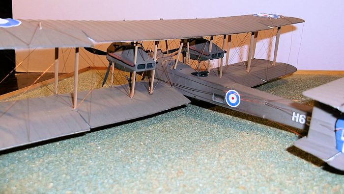 r Frog discontinued its production, and again by Eastern Express when Novo
ceased to trade. It is relatively rare now but kits can be found on second hand
sites if one is persistent. Basically, it is reasonably accurate, but it shows
its age and does require a considerable amount of work if an acceptable RAF
replica is to result. The wings in particular are very thick and need the over
heavy rib detail sanding down, the guns need to be replaced and the bombs look
like poor copies of practice bombs used in the inter-war years. There is almost
no internal detail. Most of the work is fairly straightforward, albeit
time-consuming, but not beyond the scope of the average modeller of biplanes. I
would not recommend it to anybody who has not previously tackled a biplane
however as there are one of two occasions when several pairs of hands are
needed, not to mention a fair degree of patience. However, the result is well
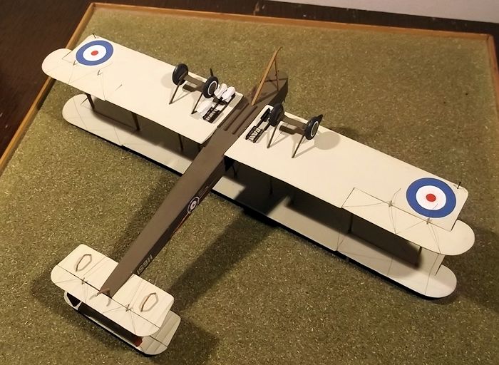
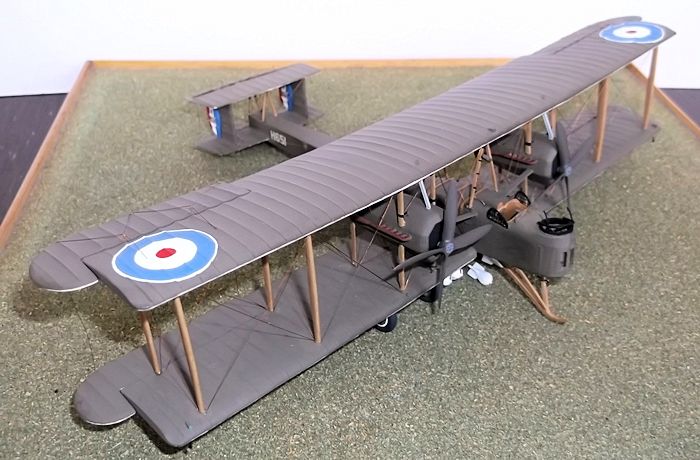
worth the effort as I hope the accompanying illustrations show and in view of
the fact that kits of large biplane are relatively rare, and that no other kit
of a Vimy has been issued in 1/72 scale, this leaves the modeller with very
little choice.
r Frog discontinued its production, and again by Eastern Express when Novo
ceased to trade. It is relatively rare now but kits can be found on second hand
sites if one is persistent. Basically, it is reasonably accurate, but it shows
its age and does require a considerable amount of work if an acceptable RAF
replica is to result. The wings in particular are very thick and need the over
heavy rib detail sanding down, the guns need to be replaced and the bombs look
like poor copies of practice bombs used in the inter-war years. There is almost
no internal detail. Most of the work is fairly straightforward, albeit
time-consuming, but not beyond the scope of the average modeller of biplanes. I
would not recommend it to anybody who has not previously tackled a biplane
however as there are one of two occasions when several pairs of hands are
needed, not to mention a fair degree of patience. However, the result is well
worth the effort as I hope the accompanying illustrations show and in view of
the fact that kits of large biplane are relatively rare, and that no other kit
of a Vimy has been issued in 1/72 scale, this leaves the modeller with very
little choice.
| CONSTRUCTION |
The Fuselage
Start
by filling in the rear fuselage windows with blanks of plastic card and cut new
openings for the windows 18 mm forward of the old ones. Cut out a new under-gun
position in the underside of the fuselage: the forward edge needs to be directly
in line with the forward edge of the new side windows and is 7mm wide and 15 mm
long. The rear 8 mm should be filled with a piece of clear acetate sheet to
represent the gunner's window. (Note: I did not do this on my model as I was
unaware of this gun position when I made mine over 35 years years ago). Remove
the upper fuselage decking from a line 22 mm behind the vertical stitching on
the mid-fuselage side to the pilot's cockpit and blank off the engine control
entry slots with plastic card. Next cut new floors for the front and rear
cockpits from plastic card and add to one of t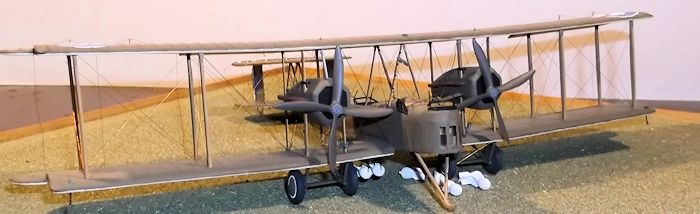 e fuselage halves. Put the rib
and stringer detail in the cockpit areas from thin rod or stretched sprue. New
seats are required in all three cockpits - these can be made from scrap card or
taken from the spares box. A new control panel and bulkhead need to be fitted to
the front of the pilot's cockpit and the rear of the front gunner’s cockpit
respectively. Cut off the control wheel from the control column and replace the
column with a longer piece of rod, then add rudder bar, throttle controls etc to
the cockpit area as desired. You will need a gun mount for the lower gun in the
rear gunner's position. Paint the fuselage interiors and the extra details and
allow to dry.
e fuselage halves. Put the rib
and stringer detail in the cockpit areas from thin rod or stretched sprue. New
seats are required in all three cockpits - these can be made from scrap card or
taken from the spares box. A new control panel and bulkhead need to be fitted to
the front of the pilot's cockpit and the rear of the front gunner’s cockpit
respectively. Cut off the control wheel from the control column and replace the
column with a longer piece of rod, then add rudder bar, throttle controls etc to
the cockpit area as desired. You will need a gun mount for the lower gun in the
rear gunner's position. Paint the fuselage interiors and the extra details and
allow to dry.
Join the two fuselage
halves together and allow to dry out thoroughly (i.e. overnight). Fill any bad
joints and the holes for the engine bearer entry ports. Cut out the area in the
nose where the glazing should be and either add new windows from small pieces of
clear acetate sheet or a block of clear Perspex. If the latter method is chosen,
file the Perspex to shape and restore the clarity by polishing with very fine,
worn glass paper, and finally toothpaste or metal polish. Then cement three
curved plastic formers into the gap left in the upper fuselage by the removal of
the upper decking. Cut a piece of 10 thou plastic card to fit over the gap and
cut slots so that formers may protrude, and slip the card onto the fuselage.
When in place secure with liquid cement.
Fill the rear gunner’s cockpit opening and cut out a new one 22 mm
further forward by using the points of a pair of dividers: rotate the dividers
and score the hole for the opening. Mould a new fuselage after-decking from 30
thou plastic card and attach this to the top of the fuselage aft of the pilot's
cockpit. The formers will act as both guides and anchorage points and give added
strength to this region. When the new decking has had time to try out thoroughly
fill any small gaps and joints and rub down the whole of the fuselage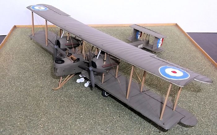 assembly.
Add the pilot's headrest from scrap plastic, and a coaming to the rear of the
cockpit from thin rod or stretched sprue. Drill four holes in the top of the new
fuselage port decking and add four short lengths of rod to represent the fuel
tank filler caps. Cement three strips of 10 x 10 thou card across the new
fuselage moulding to represent the leather straps over the fuel tank
compartment. Last of all drill new holes for the engine control entry ports in
the correct positions and drill
small slots to represent the foothold on the port fuselage side.
assembly.
Add the pilot's headrest from scrap plastic, and a coaming to the rear of the
cockpit from thin rod or stretched sprue. Drill four holes in the top of the new
fuselage port decking and add four short lengths of rod to represent the fuel
tank filler caps. Cement three strips of 10 x 10 thou card across the new
fuselage moulding to represent the leather straps over the fuel tank
compartment. Last of all drill new holes for the engine control entry ports in
the correct positions and drill
small slots to represent the foothold on the port fuselage side.
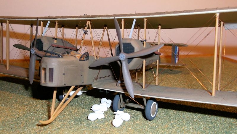
Engines
Start by assembling the
engine parts (minus the props) and set aside to dry. Cut new plates from 20 thou
plastic card and fit these to the indents in the upper parts of the engine
cowlings. You may find that a little internal bracing would be helpful to
prevent the card from bending during later cleaning up operations. When the
assembly has dried out fill any cracks with filler and rub down. Then replace
the vertical brace in the rear of the cowling with a piece of thin rod or
Evergreen strip and make new exhausts: I used the kit parts for the forward half
and reshaped cocktail sticks for the rear portion. Note that both the front and
rear portions taper towards the joint. If you are modelling the later style of
exhausts, remove the rear section of the kit parts and cement directly to the
cowling sub-assembly. Finally re-scribe any detail lost during the rubbing down
and cleaning up operations.
Wings
 The kit wingspan is 4
mm (scale one foot 6 inches) too short. The purist will want to correct this by
adding an extra piece at the point where the wing changes from anhedral to
dihedral. I chose not to modify the wingspan, as it is not noticeable on the
finished model and seemed a great deal of tedious work for little gain. I did
rub down the over heavy rib detail, and the wing walkways on the lower main
planes however, and attempted to sand down the trailing edges of all the flying
services. Fill the ejector marks on the underside of the wings and rub these
down at the same time. Assemble the upper wing sections and ensure that the
correct 3° dihedral is maintained. This is best achieved by supporting the outer
wings with matchsticks. When the joints are dry, fill them and rub them down.
Cement the lower wings to the fuselage taking care to ensure that the correct
anhedral and dihedral are achieved. Some jigging of the model may be required
during these operations, while it is drying out. When the assembly is thoroughly
dry (after 24 hours), fill the gaps around the fuselage and rub down.
The kit wingspan is 4
mm (scale one foot 6 inches) too short. The purist will want to correct this by
adding an extra piece at the point where the wing changes from anhedral to
dihedral. I chose not to modify the wingspan, as it is not noticeable on the
finished model and seemed a great deal of tedious work for little gain. I did
rub down the over heavy rib detail, and the wing walkways on the lower main
planes however, and attempted to sand down the trailing edges of all the flying
services. Fill the ejector marks on the underside of the wings and rub these
down at the same time. Assemble the upper wing sections and ensure that the
correct 3° dihedral is maintained. This is best achieved by supporting the outer
wings with matchsticks. When the joints are dry, fill them and rub them down.
Cement the lower wings to the fuselage taking care to ensure that the correct
anhedral and dihedral are achieved. Some jigging of the model may be required
during these operations, while it is drying out. When the assembly is thoroughly
dry (after 24 hours), fill the gaps around the fuselage and rub down.
The Tailplane
Attach the lower
horizontal surfaces and allow to dry but do check the alignment of the leading
edges as I found that some minor adjustments were necessary on these parts.
After filling any gaps on the lower surface joints add the fins and cabane
struts and before these are properly set add the upper horizontal surfaces.
Again allow to dry out thoroughly before filling any poor joints and rubbing
down.
Main Assembly
Cut new engine bearers
struts from plastic card and shape to aerofoil section as the ones supplied in
the kit are much too thick. On the forward lower struts cut out the small
locations for the steps: note that the rear engine bearers struts can be cut
from one piece of card for each side of the engine, as this will make them
stronger. Cut new cabane struts from plastic card and drill new locating holes
in the fuselage upper decking .
You now have a choice:
some people prefer not to add the top wings to biplanes until after painting is
complete. If you decide to follow this principle, carry on with the next
section, if not paint the model now. I preferred to attach the top wing at this
stage, because I found that with large biplanes painting the area between the
wings is not a problem, and it saves handling and therefore marring the
paintwork.
 Cement the engine
bearer struts to the engines and when dry attach the sub-assemblies to the lower
wing. Add the control coamings between the engines and the fuselage and allow to
dry out thoroughly. Then attach the main struts to the lower wing and the cabane
struts to the fuselage and before these have properly set, lower the top wing on
to the struts and use jigs to hold the wing in place while it dries out. This
will ensure that the struts are properly aligned and the wing is reasonably
strong. (When I built my model I had a disaster because I was moving from one
house to another and had the model in the back of a car. When I arrived at my
new home after a three hour journey I had to stop suddenly and the model nose
dived on to the floor: the top wing and some struts parted company with the rest
of the model and some unprintable language followed. Fortunately I was able to
repair the damage).
Cement the engine
bearer struts to the engines and when dry attach the sub-assemblies to the lower
wing. Add the control coamings between the engines and the fuselage and allow to
dry out thoroughly. Then attach the main struts to the lower wing and the cabane
struts to the fuselage and before these have properly set, lower the top wing on
to the struts and use jigs to hold the wing in place while it dries out. This
will ensure that the struts are properly aligned and the wing is reasonably
strong. (When I built my model I had a disaster because I was moving from one
house to another and had the model in the back of a car. When I arrived at my
new home after a three hour journey I had to stop suddenly and the model nose
dived on to the floor: the top wing and some struts parted company with the rest
of the model and some unprintable language followed. Fortunately I was able to
repair the damage).
The main undercarriage
can now be added. There should be few problems with this except to ensure that
the axles are parallel to the ground and the legs are at the correct angle. This
may require a little trimming of the undercarriage legs. Leave the wheels off
until painting is complete. The nose skid as supplied in the kit is of the wrong
cross section: it should be triangular with a flat side facing the underside of
the fuselage. The support struts are also too short, so a new skid and struts
should be fashioned from plastic card, attached to the nose and allowed to dry.
New propeller guards were added to each side of the cockpit from thin rod and
the wires added from thin copper wire. The bomb rails can be put under the wings
and fuselage from strips of plastic card. The racks and bombs can be fitted
after the painting is complete.
| COLORS & MARKINGS |
Naturally the colour
scheme will vary according to the aircraft chosen. Those aircraft which had
uniform colours (e.g. Nivo or silver dope) are best spray painted if possible.
If natural linen features in your colour scheme I found that a mix of paints
based on the proportions of three parts Humbrol matt white (34), one part clear
doped linen (74), and one quarter part medium grey gives a colour approaching
the creamy grey of linen. Individuals will want to mix their exact shade but the
above acts as a good starting point from
 which further experimentation can be
carried out. Tyres should be dark grey and the struts and nose skid a light
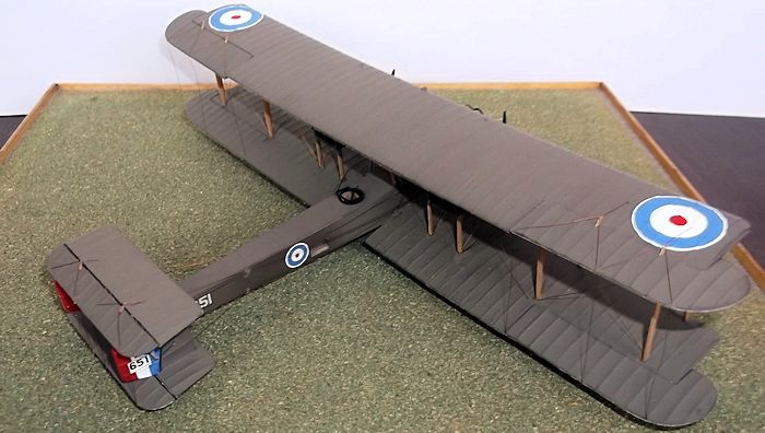
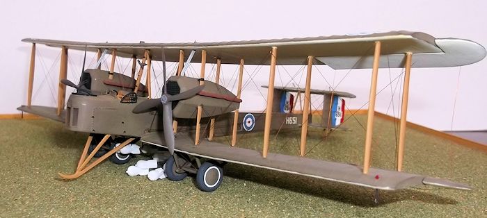
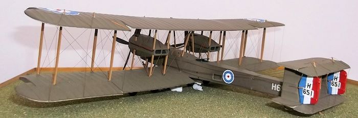
brown (natural wood). Markings for H651 are provided in the kit and I chose to
model this particular aircraft as it was used at the Royal Aircraft
Establishment at Farnborough where it was used for bombing trials. It happens
that as a child I used to watch aircraft from Farnborough from our kitchen
window and garden as they flew circuits testing equipment, although H651 was not
among them! H651 propellers were natural wood: on some machines they were fitted
with metal covers when they would have been dark grey. The cockades were
hand-painted on my model (the transfers in the kit were too thin), as were the
rudder stripes. For those who are unhappy about hand painting cockades (as
indeed I was), I can assure you that it is not too difficult a process. First
scribe on the outer circle of the cockades with a sharp pair of dividers and
then painted the circle in with white paint. As the white appears in the
cockades two coats may be needed to achieve the correct density. With great
care, thin paint and a fine brush the paint can be allowed to run into the
groove made by the dividers and a neat outline will result. When the white paint
is dry scribe on circles for the red and blue, again using dividers, and
complete the painting as described above. Provided enough care and patience are
exercised no touching up will be required and as good or better finish will be
achieved than if transfers had been used. I regularly paint the cockades on my
models now and find that it is just as easy as using transfers and I do not have
to use softeners or varnishes afterwards.
which further experimentation can be
carried out. Tyres should be dark grey and the struts and nose skid a light
brown (natural wood). Markings for H651 are provided in the kit and I chose to
model this particular aircraft as it was used at the Royal Aircraft
Establishment at Farnborough where it was used for bombing trials. It happens
that as a child I used to watch aircraft from Farnborough from our kitchen
window and garden as they flew circuits testing equipment, although H651 was not
among them! H651 propellers were natural wood: on some machines they were fitted
with metal covers when they would have been dark grey. The cockades were
hand-painted on my model (the transfers in the kit were too thin), as were the
rudder stripes. For those who are unhappy about hand painting cockades (as
indeed I was), I can assure you that it is not too difficult a process. First
scribe on the outer circle of the cockades with a sharp pair of dividers and
then painted the circle in with white paint. As the white appears in the
cockades two coats may be needed to achieve the correct density. With great
care, thin paint and a fine brush the paint can be allowed to run into the
groove made by the dividers and a neat outline will result. When the white paint
is dry scribe on circles for the red and blue, again using dividers, and
complete the painting as described above. Provided enough care and patience are
exercised no touching up will be required and as good or better finish will be
achieved than if transfers had been used. I regularly paint the cockades on my
models now and find that it is just as easy as using transfers and I do not have
to use softeners or varnishes afterwards.
| FINAL CONSTRUCTION |
Add the top wing if you
have not already done so. Control horns, generators and propellers, wheels, fuel
pipes, steps and braces on the engine struts and cowlings, and other details
should all now be added. On the RAF machines, new gun rings and bomb racks can
be added or alternatively, these may be left until after the rigging operations
are complete. Rigging this aeroplane is a long and somewhat tedious operation
but it does make a big difference and adds much to the model. Many kinds of
materials can be used: stretched sprue, monofilament nylon thread and copper
wire are the most common. I have tried all three at some time and find that
44SWG copper wire was the best because it gave the most consistent result, was
near to scale thickness (though it is still grossly over thick), and was fairly
easy to apply. The techniques for rigging are the similar whatever materials you
decide to use. I used the following method: measure the correct length on
 the
model using dividers and cut a piece of wire. Using a pin or toothpick put a
tiny drop of superglue onto the model where one end of the wire is to be
attached, put a second drop of glue at the other attachment point and add the
wire while the glue is still wet. If you are using stretched sprue use liquid
plastic cement and apply with a paintbrush.
the
model using dividers and cut a piece of wire. Using a pin or toothpick put a
tiny drop of superglue onto the model where one end of the wire is to be
attached, put a second drop of glue at the other attachment point and add the
wire while the glue is still wet. If you are using stretched sprue use liquid
plastic cement and apply with a paintbrush.
When rigging a model I
follow a basic pattern which ensures the least damage to previous work, (and
hence least bad language, loss of temper and stress in the household), while at
the same time ensuring that all the wires are added. The order I used was as
follows: first tailplane and undercarriage bracing, followed by the fuselage
cabane wires and the engine bracing wires (all of them). The wing flying and
lift wires (the latter should be double) are next, starting from the inboard and
rear as these are the most difficult to get at, and then the elevator and
aileron control wires, fuselage control wires, and finally the elevator and
aileron stabiliser wires.
When the aircraft was
fully rigged I added the final details such as bombs, windscreens, machine-gun
mounts and guns, propellers, navigation lights, flare holders, etc.
| CONCLUSIONS |
I started this model
because I happened to find some old 1/48 scale drawings of the Vimy, and as I
wanted a large bomber in my biplane collection this provided me with much
information which I could use. I did not know how much work would need to be
done until I started, but as I had converted small biplanes before I just
steamed ahead. It was not too difficult and it taught me the valuable lesson
that it is surprising what you can do when you want to. No other model of the
Vimy exists in this scale, and anyway most of the problems are relatively minor
albeit a bit time consuming to put right and should be within the capacity of
those modellers who normally do super detailing. The kit is also pretty
accurate, especially considering its age, and therefore worth the time needed to
bring it up to a good standard. There are many conversion possibilities too so
there are many other opportunities here for fans of inter-war aircraft.
| REFERENCES |
The Vickers Vimy, J.M.
Bruce, Albatross Publications: this has 1/72 scale drawings which are most
helpful.
Profile No. 5:
The Vickers Vimy.
Vickers Aircraft Since
1908, C. F.
Andrews, Putnam.
The Vickers Vimy,
P. St. John Turner.
February 2015
Copyright ModelingMadness.com. All rights reserved. No reproduction in any form without express permission from the editor. If you would like your product reviewed fairly and
fairly quickly, please
contact
the editor or see other details in the
Note to
Contributors.