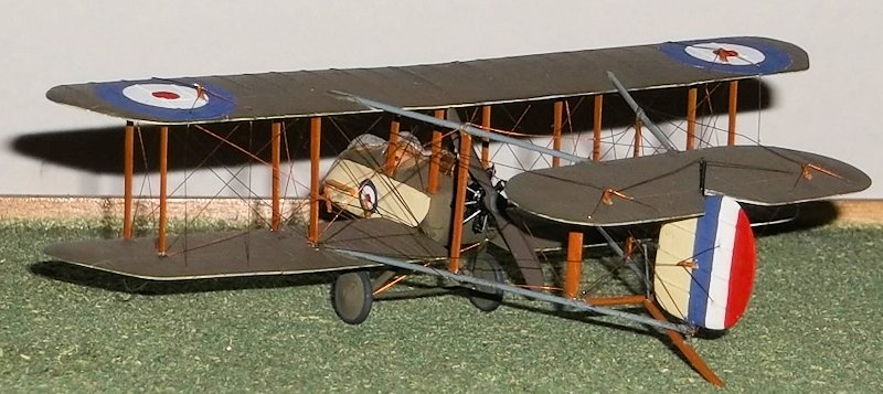
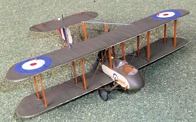
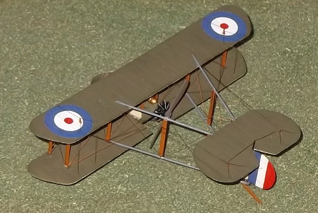
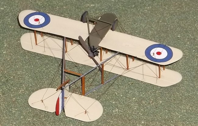
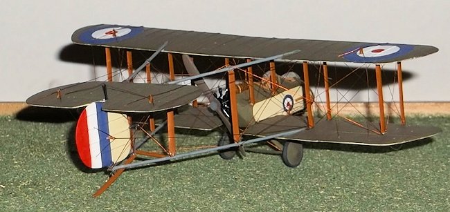
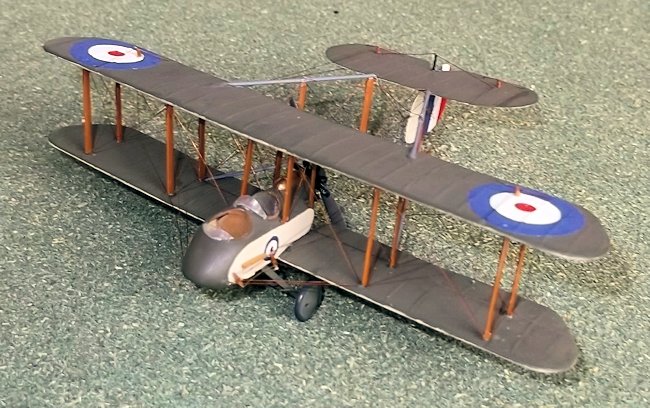
1/72 FB.9 Gunbus
| KIT #: | 01079 & 01048 |
| PRICE: | £5.00 each approx |
| DECALS: | |
| REVIEWER: | Stephen Foster |
| NOTES: | Kit-bashed |
| HISTORY |
The Vickers FB 9 was a development of the earlier and
better known FB 5 which was dubbed unofficially "Gun Bus" because it was the
first RFC machine to be armed with a machine gun. The Gun Bus was a two seater
powered by a 100 h.p. Monosoupape or 110 h.p. Le Rhone rotary engine with the
engine mounted at the rear of the fuselage with the tail mounted on booms
attached to the wings. This gave the observer/gunner in the front cockpit an
enormous field of fire. The FB 5 served in France in 1915 and early 1916.
However they were outclassed in 1915 by the Fokker and Pfalz Eindekkers
(monoplanes), so a replacement aircraft was urgently needed. Vickers thought
that they could upgrade the existing design by reducing the wingspan and
reshaping the tips, streamlining the horizontal tail surface, enlarging and
streamlining the nose, adding a simple V undercarriage, reducing some of the
rigging and
 using streamlined wires. The result was the FB 9, also known as the
"Streamline Gun Bus", but there was not a big improvement in performance, partly
because they had the same engine as the FB 5, so the type was not adopted as a
front line machine by the RFC. However a few machines (24?) were built under licence by Darracq in Paris and two of these (7822 and 7828) were certainly used
by No. 11 Squadron in the summer of 1916 at a time when the RFC was making a
maximum effort to support the Somme offensive and the squadron was having
problems with the reliability of the engines in their new FE 2b's. On 1st July
Lt. Morris (pilot) and Sgt. Glover (observer/gunner) managed to bring down a
hostile aircraft but active service at the front was short lived as the problems
with the superior FE 2b were resolved and the FB9's poor performance rendered it
obsolete as a front line machine. 95 FB 9s were built by Vickers in Britain: the
majority of these went to training units where they gave good service until well
into 1918. Their flying qualities made them suitable for this important work and
some were fitted with dual controls with the student pilot occupying the front
cockpit. Training is not a glamourous role but it is a vitally important one, so
it was interesting to add this unusual and generally little known aircraft to my
model collection.
using streamlined wires. The result was the FB 9, also known as the
"Streamline Gun Bus", but there was not a big improvement in performance, partly
because they had the same engine as the FB 5, so the type was not adopted as a
front line machine by the RFC. However a few machines (24?) were built under licence by Darracq in Paris and two of these (7822 and 7828) were certainly used
by No. 11 Squadron in the summer of 1916 at a time when the RFC was making a
maximum effort to support the Somme offensive and the squadron was having
problems with the reliability of the engines in their new FE 2b's. On 1st July
Lt. Morris (pilot) and Sgt. Glover (observer/gunner) managed to bring down a
hostile aircraft but active service at the front was short lived as the problems
with the superior FE 2b were resolved and the FB9's poor performance rendered it
obsolete as a front line machine. 95 FB 9s were built by Vickers in Britain: the
majority of these went to training units where they gave good service until well
into 1918. Their flying qualities made them suitable for this important work and
some were fitted with dual controls with the student pilot occupying the front
cockpit. Training is not a glamourous role but it is a vitally important one, so
it was interesting to add this unusual and generally little known aircraft to my
model collection.
| THE KIT |
I enjoy looking at models with a view to making something
completely different from what the manufacturer had in mind. Sometimes more than
one kit has to be used, but then the spare parts can be used in another project,
and so it goes on. (In this case and the FB 5 featured earlier, the engines came
from the Airfix Avro 504: later the wings will be used to build another
conversion, the Sopwith Gunbus.) The advantage of this is that I can build
models of aircraft that manufacturers do not or will not make. I originally
started this project over 30 years ago but then stopped modelling altogether. At
the time I was
 working on converting a Vickers FB 5 "Gunbus", and when I started
modelling again recently it seemed real shame not to finish them. I completed
the FB 9 as a trainer as this was how most of these machines were used by the
RFC between 1916 and 1918. There is no kit of the FB 9 so this is a conversion
project based on the Airfix DH 4 (kit no.01079) and the Avro 504 (kit no.
01048). It will require some experience of converting/scratch-building,
including some experience with biplanes, but as with all modelling, the most
important ingredients are care and patience. It may be possible to convert a
Merlin/Pegasus model of the FB5 but I estimate that although the amount of work
involved would be less, I am not sure that it would be much easier. At the very
least you will need to modify the fuselage, wings and tail unit and provide a
new undercarriage. Pusher aircraft do not make the strongest of models but
equally they are not as flimsy as they sometimes look - this model is certainly
stronger than it looks as I found when I dropped it on the table a couple of
times when I was rigging it! Pusher aircraft are also not popular with kit
manufacturers for obvious reasons, yet they formed an important part of the RFC
equipment during the early and middle years of WWI, so modellers often have to
build their own, especially in 1/72 scale in which I work.
working on converting a Vickers FB 5 "Gunbus", and when I started
modelling again recently it seemed real shame not to finish them. I completed
the FB 9 as a trainer as this was how most of these machines were used by the
RFC between 1916 and 1918. There is no kit of the FB 9 so this is a conversion
project based on the Airfix DH 4 (kit no.01079) and the Avro 504 (kit no.
01048). It will require some experience of converting/scratch-building,
including some experience with biplanes, but as with all modelling, the most
important ingredients are care and patience. It may be possible to convert a
Merlin/Pegasus model of the FB5 but I estimate that although the amount of work
involved would be less, I am not sure that it would be much easier. At the very
least you will need to modify the fuselage, wings and tail unit and provide a
new undercarriage. Pusher aircraft do not make the strongest of models but
equally they are not as flimsy as they sometimes look - this model is certainly
stronger than it looks as I found when I dropped it on the table a couple of
times when I was rigging it! Pusher aircraft are also not popular with kit
manufacturers for obvious reasons, yet they formed an important part of the RFC
equipment during the early and middle years of WWI, so modellers often have to
build their own, especially in 1/72 scale in which I work.
| CONSTRUCTION |
Start with the fuselage. This has to be moulded using balsa
wood and plywood. From a plan of the fuselage trace the side profile and
transfer this to a block of balsa wood 7/16 inch thick. If the block is a little
thicker it does not matter as it can be sanded to the correct size. Now cut a
former from card the shape of the cross section of the fuselage between the
cockpits - you can use the DataFile 56 FB 5 for this if necessary as the shape
was the same for both types. Carve and sand the balsa block to the correct shape
while continually referring to the plans and former to make sure that you do not
take off too much wood. The finished mould should be smooth and very slightly
smaller than the drawing to allow for the thickness of plastic to be moulded.
When you are happy with your nacelle draw another side profile on to
 a piece of
three or five plywood, leaving a margin of at least two inches all around. Cut
out a hole the shape of the fuselage profile and sand this smooth, making sure
that it exactly fits the plan. Check that the balsa mould will pass through the
cut-out leaving enough room for the plastic i.e. about 10 thou all round. Take a
piece of 30 thou plastic card and pin it over the hole in the plywood, allowing
at least one inch of surround. Hold the wood with a heatproof glove and put the
plastic and wood under a grill with the plastic side facing the heat source and
heat it gently. When the plastic starts to wrinkle and curl a little at the
edges take it away from the heat and push the balsa mould into the plastic
through the hole in the plywood. Stop pushing when the balsa mould is just over
half-way through. Wait for the plastic to cool and remove it from the plywood,
then very gently ease the balsa mould out of the plastic. This will give you one
half of your fuselage nacelle. Repeat the above operation but this time put the
plastic sheet on the other side of the plywood mould and push the balsa mould
through the heated plastic card from the other side: this will give you the
second half of the nacelle. Carefully cut out the two new parts using a very
sharp scalpel knife and gently sand the edges until they are flat. Put the two
halves together and check for size against the plan. Sand down the edges of both
halves until the width is correct and you have a good join. Finally cut out the
two apertures for the cockpits so that they match exactly.
a piece of
three or five plywood, leaving a margin of at least two inches all around. Cut
out a hole the shape of the fuselage profile and sand this smooth, making sure
that it exactly fits the plan. Check that the balsa mould will pass through the
cut-out leaving enough room for the plastic i.e. about 10 thou all round. Take a
piece of 30 thou plastic card and pin it over the hole in the plywood, allowing
at least one inch of surround. Hold the wood with a heatproof glove and put the
plastic and wood under a grill with the plastic side facing the heat source and
heat it gently. When the plastic starts to wrinkle and curl a little at the
edges take it away from the heat and push the balsa mould into the plastic
through the hole in the plywood. Stop pushing when the balsa mould is just over
half-way through. Wait for the plastic to cool and remove it from the plywood,
then very gently ease the balsa mould out of the plastic. This will give you one
half of your fuselage nacelle. Repeat the above operation but this time put the
plastic sheet on the other side of the plywood mould and push the balsa mould
through the heated plastic card from the other side: this will give you the
second half of the nacelle. Carefully cut out the two new parts using a very
sharp scalpel knife and gently sand the edges until they are flat. Put the two
halves together and check for size against the plan. Sand down the edges of both
halves until the width is correct and you have a good join. Finally cut out the
two apertures for the cockpits so that they match exactly.
Start adding cockpit details by glueing the internal
bracing on the sides from thin rod or stretched sprue and a floor from card. You
need two seats for the pilots plus control columns and rudder bars. Instruments
were basic - there were no panels as such. Seat belts can be added from thin
paper. Paint the interior of the cockpits clear doped linen on the sides, metal
for the front and upper curved sections and wood for the floor. Glue the floor
to one side of the fuselage nacelle and cement the two halves together with
liquid glue. If there are any very small cracks these can be filled and rubbed
down. Make a fuel tank - I used a piece of sprue which I filed to shape using
the plan. Two thin bands need to be added from thin rod and glued into place
using liquid cement. Glue the tank to the rear fuselage and fair it in with
filler and sand smooth. Drill a very small hole in the top and add a tiny piece
of very thin stretched s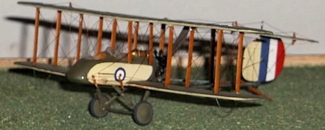 prue to represent the filler cap. Add the cockpit
coamings from stretched sprue or thin rod and then cement a small piece of
circular 10 thou card on to the top of the rear of the fuselage where the engine
will be mounted. Drill a small hole in the card disc to take the pin on the
rotary engine: check the size of the pin on the engine, (mine was from an from
an Airfix Avro 504), but you could use another source), for the size of the
hole. Do not put the engine on at this stage. Cut two small rectangles from 5
thou card to represent the steps on each side of the front cockpit and glue into
place using liquid cement. You will also need two small fairings on each side of
the fuselage just behind and below the steps. Mark on to the fuselage the
positions for the struts for the top wing and cut out small holes.
prue to represent the filler cap. Add the cockpit
coamings from stretched sprue or thin rod and then cement a small piece of
circular 10 thou card on to the top of the rear of the fuselage where the engine
will be mounted. Drill a small hole in the card disc to take the pin on the
rotary engine: check the size of the pin on the engine, (mine was from an from
an Airfix Avro 504), but you could use another source), for the size of the
hole. Do not put the engine on at this stage. Cut two small rectangles from 5
thou card to represent the steps on each side of the front cockpit and glue into
place using liquid cement. You will also need two small fairings on each side of
the fuselage just behind and below the steps. Mark on to the fuselage the
positions for the struts for the top wing and cut out small holes.
If
you use the engine from the Avro 504 you will need to cement thin lengths of
stretched sprue or very thin rod to the front of the cylinders to represent the
push rods. This engine is not strictly accurate but it is passable in this
scale. The Avro propellor can also be used provided it is shortened and the tips
reshaped - just cut off the pin and drill a small hole in the front of the
propellor and insert the pin. Cut a disc of 5 thou card for the boss on the rear
of the propellor and represent the bolts by pushing a sharp pin from behind.
Cement the disc to the propellor. When the engine and propellor have been
painted cement them together: the engine was black with silver push rods and the
propellor natural wood. Set this assembly on one side for later.
The wings are next. Take the bottom wing from the DH 4 and
cut out the central section. On each lower wing half trace the shape of the tips
from the plan and cut and shape the tips and sand them smooth. Place one wing
half on the plan and lay the fuselage nacelle on top so that you can accurately
measure how much of the inner part of the wing needs to be removed. Cut this off
with a small piece to spare - it can be sanded to the exact size later. Repeat
for the other wing half. Take the top wing of the DH4 and again reduce the span
by removing the tips using the plan and reshape the tips. On all the wing
sections fill the locating holes/grooves for the struts, the aileron grooves,
and any ejector marks. You will also need to fill the cut-outs on the trailing
edges of all the wing sections with 40 thou card and sand to the correct
aerofoil shape. Rub down all of the moulded ribs on the wings and score shallow
grooves on the line of the ribs of the FB 9. Use liquid cement to stick thin rod
or stretched sprue into the grooves and when this is dry rub down gently until
they are just prominent on the surface. Score grooves for the new ailerons on
the wings, and drill new holes for the struts. Now for the booms and tail unit.
You can use either wire or plastic rod for this: I use wire on my models because
it is stronger. Cut the rod for the booms to the correct length: the lower booms
formed a V under the rudder but the top booms attached to the front edge of the
horizontal tail surface. For a stronger model I advise that you make the upper
booms the same length as the lower ones and lay the tail unit on them, although
I did not do so and instead cut two small slots and epoxy glued the rods
directly to the horizontal tail unit. The horizontal and vertical tail surfaces
were cut from 20 thou plastic card which was sanded to aerofoil section and the
elevators and rudder were scribed on to the surface. Add ribs to the top surface
of the horizontal unit and the
 fin/rudder as per the wings. Cut two short
lengths of stretched sprue and glue these to the top and bottom of the
fin/rudder joint to represent the rudder posts: these will also make the
attachment points on the booms. A small piece of sprue needs to be glued on the
port (left) side of the leading edge of the fin: this will take bracing wires to
the booms and the tail skid.
fin/rudder as per the wings. Cut two short
lengths of stretched sprue and glue these to the top and bottom of the
fin/rudder joint to represent the rudder posts: these will also make the
attachment points on the booms. A small piece of sprue needs to be glued on the
port (left) side of the leading edge of the fin: this will take bracing wires to
the booms and the tail skid.
Sand the lower wing halves to the exact length and then
carefully cement the lower wing halves to the nacelle making sure that they are
perpendicular to the fuselage sides and that you get the correct dihedral angle
by holding up the tips while they dry out. Fill any gaps with filler and sand
down. Mark where the booms will need to be attached by laying the wings and a
length of brass or steel rod on the plan and score the wings carefully. You will
need to cut a short shallow groove which gets deeper forward of the trailing
edge. This can be achieved by marking where the boom will sit on the top surface
of the lower wings. Use a needle file and gently twist this over the line while
pushing downwards: the point of the file will dig into the wing more quickly and
will give a groove with a deeper leading edge. Repeat this exercise on the top
wing but in this case the front end of the groove will not need to be so deep.
Now glue the booms to the upper and lower wings either with epoxy or CA, again
making sure that you get the correct angle by lifting the forward edges of the
wings while the booms dry out. If you wish to insert the booms into the leading
edge of the tailplane the horizontal tail surface should have two small knicks
cut into the leading edge where the booms are to be glued: epoxy these into
place ensuring that the booms and tail surface are level. Alternatively if your
tail surface is to rest on the boom do not make the knicks. Add the horizontal
strut between the lower booms from rod - the location can be taken from the
plan.
| COLORS & MARKINGS |
I paint my biplanes before adding the top wing as this
makes the operation straightforward. The lower surfaces of the wings and
tailplane, and sides of the nacelle and fin are clear doped linen, the upper
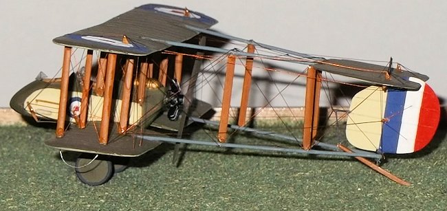 surfaces and wheel discs are PC 10. The fuel tank is copper and the booms are
light grey. I hand painted the rudder stripes and cockades: you could use the
wing cockades from the DH 4, but you may need to paint the nacelle markings
unless you can find a cockade small enough. I could not find a photo of a
machine with a serial, but if you add one it should be in black on the rudder.
PC 10 was a variable colour which was an olive green with a touch of brown when
fresh but it weathered to chocolate brown over time. I also made a mistake with
the upper wing and fuselage cockades by not putting on the white outlines, but I
remembered this too late and am not prepared to risk damaging the model trying
to rectify it. Very few people know anyway so what the hell?! The struts were
light brown.
surfaces and wheel discs are PC 10. The fuel tank is copper and the booms are
light grey. I hand painted the rudder stripes and cockades: you could use the
wing cockades from the DH 4, but you may need to paint the nacelle markings
unless you can find a cockade small enough. I could not find a photo of a
machine with a serial, but if you add one it should be in black on the rudder.
PC 10 was a variable colour which was an olive green with a touch of brown when
fresh but it weathered to chocolate brown over time. I also made a mistake with
the upper wing and fuselage cockades by not putting on the white outlines, but I
remembered this too late and am not prepared to risk damaging the model trying
to rectify it. Very few people know anyway so what the hell?! The struts were
light brown.
| FINAL CONSTRUCTION |
I used the wing struts from the DH 4. Start by cementing
the four outer struts in the holes on the underside of the upper wing, then
place small blobs of glue into the outer holes on the lower wing and carefully
lower the top wing and struts into the holes on the lower wing. When this
assembly is still drying put the fin/rudder into place between the rear of the
booms and/or the horizontal tail unit, using the small posts on the rudder to
secure it. Line up the wings, struts and booms so that all is square and support
the assembly while it dries out. When all is dry you can carefully measure the
lengths of the inner wing and fuselage struts with a pair of dividers. Cut the
struts to the correct length and measure them again to make sure that you have
done this accurately. When you are satisfied that the struts are the correct
length glue them into place. You will not need to support the wing and booms
again while this dries out. When it is dry you can measure the lengths of the
boom struts with a pair of dividers and cut them from card, or use struts from
the Avro 504 if you do not want to make a Sopwith Gunbus, before glueing into
position with superglue. Be careful with this assembly as it is a bit fragile
while under construction, but when it is completed and has dried out properly it
is quite rigid. Cut a pair of undercarriage legs from 20 thou card and shape to
aerofoil section. Place the tops of the legs on the base of the nacelle, mark
the positions and cut out the shallow indentations in the bottom of the nacelle
to take the legs. Cut a length of plastic rod for the axle and pass it through
holes drilled at the base of the legs and glue the tops of the legs to the
bottom of the fuselage. Make sure that they set in the correct position and then
glue on the wheels. Now paint the struts and steps on the nacelle a light wood,
wheel tyres dark grey and undercarriage legs and wheel discs PC 10. Cut and fit
four control horns for the fuselage controls, and horns for the elevators,
ailerons and rudder and glue into place and paint light brown. Finish any other
painting and touching in.
Rigging.
I use very thin wire for the rigging as it is very
difficult to pull monofilament thread taught on what is a delicate and small
model. Measure each length of wire on the model using a pair of dividers and
glue into place with superglue. This model has a large number of individual
strands so it will take a long time. So as not to miss any wires start with
those between the fuselage struts, then the rear of the wings and the fore-aft
wires between the wing struts. Now is the time to fit the engine and propellor.
Run control wires from the control horns on the fuselage to the rear of the
fuselage. Complete the wings with the front wires and aileron linking wires.
Then rig the booms, starting at the front, and then the tail. The short wires
from the control horns to the trailing edges of the ailerons are next, followed
by the elevators and rudder, and from the tail unit control surfaces to the rear
of the wings. Finally add the anti-drag wires from the booms to the rear outer
struts and from the front of the nacelle to the front struts: this way you will
reduce your chances of damaging work already done. Add a tail skid, cut and
shaped from card and painted light brown, with a small hole drilled in the top
surface to glue to the bottom of the rudder post which should extend beneath the
lower boom, and add the small spring to the post on the leading edge of the fin
from stretched sprue. Finally cut two windscreens from very thin acetate (I used
the plastic from the old bubble pack of one of the Airfix kits), and glue a
small length of stretched sprue to the front inner strut on the port (left) side
to represent the pitot tube.
| CONCLUSIONS |
If you think that this is a lot of work you would be right,
and I would not recommend it to anyone who has not tried doing some conversion
work and certainly not if you have not already rigged a couple of biplanes
(though not necessarily in 1/72 scale). I had not made a model in decades until
recently, so I had
 tried a couple of easier biplanes first before attempting to
finish this. The most difficult parts were undoubtedly fitting the wings and
booms, and then the rigging. It is a long build so you might want to put it to
one side for a while (but not for 30+ years!), and have a go at something
simpler and quicker and then come back to it, or make an easier model at the
same time. I measure satisfaction from my modelling by the comments that people
make when they see my models and I get many positive noises about this one.
People even ask me where did I buy the kit but as far as I am aware none exists
and I have never seen an article on this conversion. I also get satisfaction in
proportion to the challenge offered: this one was very satisfying!
tried a couple of easier biplanes first before attempting to
finish this. The most difficult parts were undoubtedly fitting the wings and
booms, and then the rigging. It is a long build so you might want to put it to
one side for a while (but not for 30+ years!), and have a go at something
simpler and quicker and then come back to it, or make an easier model at the
same time. I measure satisfaction from my modelling by the comments that people
make when they see my models and I get many positive noises about this one.
People even ask me where did I buy the kit but as far as I am aware none exists
and I have never seen an article on this conversion. I also get satisfaction in
proportion to the challenge offered: this one was very satisfying!
| REFERENCES |
There are very few that I could find, but
Warplanes of the First world War: Fighters
Vol. 3 by J. M.Bruce was the best source. See also
The British Fighter Since 1912 by P.
Lewis. For plans I suggest that you use the plans for the FB 5 in the Windsock
DataFile no 56 combined with plans available on the internet. The ones I used
were an old Aeromodeller set which were usable but are now out of print: some of
the internet plans that I have seen seem to have been derived from a similar
source.
There is an article on making parts using the moulding
technique described here in
www.airfixtributeforum/top-tips-and-techniques.
Stephen Foster
July 2013
Thanks to for the review kit. You can find this one at your favorite hobby shop or on-line retailer.
If you would like your product reviewed fairly and fairly quickly, please contact the editor or see other details in the Note to Contributors.