"Airfix" 1/72 Vickers FB.5 Gunbus
| KIT #: |
01079 and 01048 |
| PRICE: | £5.00 each |
| DECALS: | |
| REVIEWER: | Stephen Foster |
| NOTES: | Kitbash using Airfix DH.4 and Avro 504 |
| HISTORY |
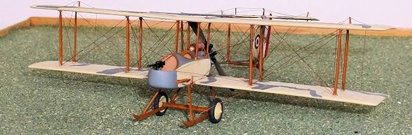
The Vickers FB 5 was dubbed unofficially the "Gun Bus" because it was the first
RFC machine to be armed with a machine gun. It was a two seater powered by a 100
h.p. Monosoupape or 110 h.p. Le Rhone rotary engine, but because there was no
interrupter gear available to stop bullets from striking the propellor blades,
the engine had to be mounted at the rear of the fuselage nacelle in what is
called a pusher configuration: the tail unit was carried on booms attached to
the wings. This gave the observer/gunner an enormous field of fire in the
unlikely event that the aircraft should meet an enemy. It was designed to an
Admiralty specification for a fighting aeroplane and the first prototype was
produced in 1913 as an armed photographic reconnaissance machine. The first FB5
was accepted by the RFC in October 1914, with machines being taken to France in
February 1915 by No. 2 Squadron. These were some of the few aircraft to be armed
at this time, so they quickly gained a reputation for being dangerous: the
characteristic pusher layout and impact that these aircraft had because they
were armed meant that the Germans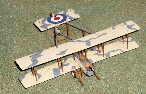 henceforth called all British pusher types
"Vickers," irrespective of the manufacturer or design. In July 1915 the first
fighter or pursuit squadron in any air service to be formed and equipped with a
single aircraft type with the specific purpose of fighting and destroying enemy
machines was No 11 Squadron RFC which used the FB 5. However F B 5 Gun Buses
quickly became obsolete as they were too slow and were therefore outclassed by
the Fokker and Pfalz Eindekkers (monoplanes), so they were withdrawn from front
line service in the spring of 1916.
henceforth called all British pusher types
"Vickers," irrespective of the manufacturer or design. In July 1915 the first
fighter or pursuit squadron in any air service to be formed and equipped with a
single aircraft type with the specific purpose of fighting and destroying enemy
machines was No 11 Squadron RFC which used the FB 5. However F B 5 Gun Buses
quickly became obsolete as they were too slow and were therefore outclassed by
the Fokker and Pfalz Eindekkers (monoplanes), so they were withdrawn from front
line service in the spring of 1916.
The Danish
Arsenal Workshops bought a licence to build 12 machines which entered service in
1917 but they were not used for very long because the Monosoupape engines were
so unreliable. Indeed the poor serviceability of the engines plagued the machine
in RFC service, with many sorties having to be aborted because of engine
failure. One pilot reported having to return to his airfield on over 20
occasions out of 40 because of engine problems. Nonetheless the pilots and
observers had some success with these aircraft, with Lt. A. J. Insall being
awarded a VC in 1915 and several pilots managed to "make ace" (force down more
than 5 machines) with this type, no mean feat in a slow and not very
manoeuvrable aircraft.
When I started this project over 30 years ago there was no kit of the FB 5, nor
indeed any prospect of one, although Pegasus/Merlin have produced one since, and
these can be obtained on e-bay or other sources, although the author considers
them to be rather expensive and they have been described as an aid to scratch
building. That said this is a conversion project based on the Airfix DH 4 (kit
no.01079) and the Avro 504 (kit no. 01048). It is worthy of note that the Airfix
DH 4 and Avro 504 kits were two of the most useful in the WW1 range as they
provide parts for so many conversion possibilities, so if you are interested in
building less well known aircraft that are avoided by the manufacturers then I
advise that you buy in a stock of these items when they become available. This
project requires experience of converting/scratch-building, including some
experience with biplanes and is not recommended for those who have little or no
experience with WWI subjects. Pusher aircraft do not seem to be popular with
either kit manufacturers or many modellers, yet as they formed an important part
of the RFC equipment during the early and middle years of WWI, modellers have no
choice but to build their own, especially in 1/72 scale. With a little
experience they are no more difficult then many other conversion projects.
| CONSTRUCTION |
I started with
the fuselage which has to be moulded using balsa wood and plywood. From a plan
of the fuselage nacelle, trace the side profile and transfer this to a block of
balsa wood 7/16 inch thick. If the block is a little thicker it does not matter
as it can be sanded down. Now cut a
 former from card to the exact shape of the
cross section of the fuselage between the cockpits, using the DataFile 56 FB 5
as a guide. Carefully carve the balsa block to the correct shape of the fuselage
nacelle: this requires patience and should not be rushed - continually refer to
the plans and former to make sure that you do not take off too much wood. The
finished mould should be smoothed with fine grade glass paper and when finished
should be very slightly smaller than the drawing to allow for the thickness of
plastic to be moulded. When you are happy with your nacelle draw another side
profile on to a piece of three or five layer plywood, leaving a margin of two to
three inches of wood around the outline. Cut out a hole the shape of the
fuselage profile and sand this smooth, making sure that this exactly fits the
plan. Check that the balsa mould will pass through the cut-out leaving enough
room for the plastic i.e. about 10 thou all round. Now take a piece of 30 thou
plastic card and pin it over the hole in the plywood, allowing at least one inch
of surround. Hold the wood with a heatproof glove and put the plastic and wood
under a grill with the plastic side facing the heat source and heat it gently.
Make sure that the grill and the wood are hot. When the plastic starts to
wrinkle and curl a little at the edges take it away from the heat and push the
balsa mould gently but firmly into the plastic through the hole in the plywood.
Stop pushing when the balsa mould is just over half-way through. Wait for about
15 seconds for the plastic to cool and remove it from the plywood. Then
carefully ease the balsa mould out of the plastic taking care not to damage the
male (balsa) mould. This will give you one half of your fuselage nacelle. Repeat
the above operation, but this time put the plastic sheet on the other side of
the plywood mould and push the balsa mould through the heated plastic card from
the other side: this will give you the second half of the nacelle. Carefully cut
out the two new parts using a very sharp scalpel knife and gently sand the edges
until they are flat. Put the two halves together and check for size against the
plan. Sand down the edges of both halves until the width of the new nacelle is
correct and you have a good join. Finally cut out the two apertures for the
cockpits making sure that they also match exactly.
former from card to the exact shape of the
cross section of the fuselage between the cockpits, using the DataFile 56 FB 5
as a guide. Carefully carve the balsa block to the correct shape of the fuselage
nacelle: this requires patience and should not be rushed - continually refer to
the plans and former to make sure that you do not take off too much wood. The
finished mould should be smoothed with fine grade glass paper and when finished
should be very slightly smaller than the drawing to allow for the thickness of
plastic to be moulded. When you are happy with your nacelle draw another side
profile on to a piece of three or five layer plywood, leaving a margin of two to
three inches of wood around the outline. Cut out a hole the shape of the
fuselage profile and sand this smooth, making sure that this exactly fits the
plan. Check that the balsa mould will pass through the cut-out leaving enough
room for the plastic i.e. about 10 thou all round. Now take a piece of 30 thou
plastic card and pin it over the hole in the plywood, allowing at least one inch
of surround. Hold the wood with a heatproof glove and put the plastic and wood
under a grill with the plastic side facing the heat source and heat it gently.
Make sure that the grill and the wood are hot. When the plastic starts to
wrinkle and curl a little at the edges take it away from the heat and push the
balsa mould gently but firmly into the plastic through the hole in the plywood.
Stop pushing when the balsa mould is just over half-way through. Wait for about
15 seconds for the plastic to cool and remove it from the plywood. Then
carefully ease the balsa mould out of the plastic taking care not to damage the
male (balsa) mould. This will give you one half of your fuselage nacelle. Repeat
the above operation, but this time put the plastic sheet on the other side of
the plywood mould and push the balsa mould through the heated plastic card from
the other side: this will give you the second half of the nacelle. Carefully cut
out the two new parts using a very sharp scalpel knife and gently sand the edges
until they are flat. Put the two halves together and check for size against the
plan. Sand down the edges of both halves until the width of the new nacelle is
correct and you have a good join. Finally cut out the two apertures for the
cockpits making sure that they also match exactly.
You can
now put in the cockpit details, including bracing with thin rod or stretched
sprue and a cockpit floor from card. You need seats for the pilot and observer
plus a control column and rudder bar. Instruments were basic - there was not a
panel as such. Seat belts can be a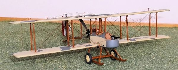 dded from thin paper, but often were not
fitted. Paint the interior of the cockpits clear doped linen on the sides, metal
for the front and upper curved sections and wood for the floor. Assemble the
fuselage and make a fuel tank from round sprue and glue it to the rear fuselage,
smooth with filler and rub down. Add a tiny piece of very thin stretched sprue
to the top of the tank to represent a filler cap, and two bands around the body
of the tank. Cockpit coamings are from stretched sprue or thin rod. A rectangle
of 5 thou card represents the step on the port side of the front cockpit. Mark
on to the fuselage the positions for the struts for the top wing and cut out
small holes, and drill a hole in the rear of the nacelle for the engine locating
pin.
dded from thin paper, but often were not
fitted. Paint the interior of the cockpits clear doped linen on the sides, metal
for the front and upper curved sections and wood for the floor. Assemble the
fuselage and make a fuel tank from round sprue and glue it to the rear fuselage,
smooth with filler and rub down. Add a tiny piece of very thin stretched sprue
to the top of the tank to represent a filler cap, and two bands around the body
of the tank. Cockpit coamings are from stretched sprue or thin rod. A rectangle
of 5 thou card represents the step on the port side of the front cockpit. Mark
on to the fuselage the positions for the struts for the top wing and cut out
small holes, and drill a hole in the rear of the nacelle for the engine locating
pin.
I used the
engine from the Avro 504 and cemented thin lengths of stretched sprue to the
front of the cylinders to represent the push rods. Shorten and reshape the
propellor of the Avro, cut off the locating pin, drill a small hole in the front
of the propellor and re-insert the pin. Cut a disc of 5 thou card for the boss
on the front of the propellor and represent the bolts by pushing a sharp pin
from behind. When the engine and propellor have been painted cement them
together: the engine was black or gunmetal with silver push rods and the
propellor natural wood. Set this assembly on one side.
Take the bottom wing from a DH 4 and cut out the central section. Trace the
shape of the tips from the plan and mark the new shape on to the wings before
cutting and shaping them. Place one wing half on the plan and lay the fuselage
nacelle on top so that you can accurately measure how much of the inner part of
the wing needs to be removed. Cut this off and file to the exact size. Repeat
for the other wing half. Take the top wing of the DH 4 and again reduce the span
and reshape the tips according to the plan. Fill all of the strut locating
holes, the aileron grooves, and any ejector marks with filler, and the slots for
the struts in the upper wing with strips of card. Straighten the upper wing so
that it has no dihedral. Fill the cut-outs on the trailing edges of the wing
sections with 40 thou card and sand to the correct shape. Rub down all of the
moulded ribs on the wings and score shallow grooves on the line of the ribs of
the FB5, using the plan as a guide. Use liquid cement to stick thin rod or
stretched sprue into the grooves and when this is dry rub down gently until they
are just prominent on the surface. Score grooves for the new ailerons on the
wings, and drill new holes for the struts, again using the plans to get the
correct locations. Mark where the booms will need to be attached to the wings by
layin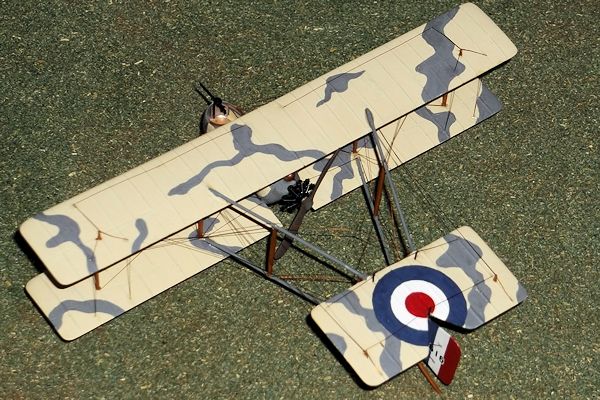 g the wings and a length of brass, steel or plastic rod on the plan, and
score shallow grooves into the top surfaces of the wings, making sure that the
groove gets deeper as it goes forward of the trailing edge.
g the wings and a length of brass, steel or plastic rod on the plan, and
score shallow grooves into the top surfaces of the wings, making sure that the
groove gets deeper as it goes forward of the trailing edge.
The
horizontal and vertical tail surfaces were cut from 20 thou plastic card which
was sanded to an aerofoil section and the elevators and rudder were scribed on
to the surfaces. Add ribs to the top surface of the horizontal unit and the
fin/rudder. Cut two short lengths of stretched sprue and glue these to the top
and bottom of the fin where it joins the rudder: these will be used to attach
the rudder to the booms. A small piece of sprue needs to be glued on the port
(left) side of the leading edge of the fin: this will take bracing wires to the
booms and the tail skid later. Cut lengths of brass, steel or plastic rod for
the booms using the plan as a guide - be sure to allow for the booms to be glued
to the tops of the wings. The lower booms formed a V under the rudder but the
top ones attached to the leading edge of the horizontal tail surface. Carefully
lay the top wing on the plan and glue the upper boom rods on to the top of the
wing and allow to dry. Cut two small slots and glue the rods directly into the
horizontal tail unit, again using the plan to ensure that alignments are
accurate. Cement the lower wing halves to the nacelle making sure that they are
perpendicular to the fuselage sides, fill any gaps and sand down. Glue the booms
to the lower wings, again making sure that you get the correct angle by lifting
the trailing edges of the wings while the booms dry out. Add the horizontal
strut between the lower booms from rod - the location can be taken from the
plan.
Now do most of the painting.
| COLORS & MARKINGS |
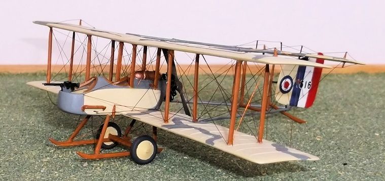
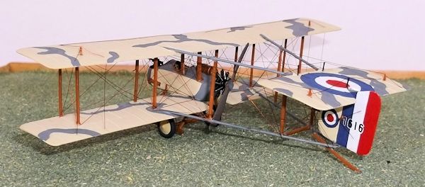
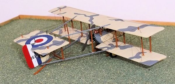
Most aircraft
were clear doped linen overall with natural metal on the nose. I painted mine in
an early camouflage scheme as used by aircraft of No 5 Squadron: the pattern is
representative - there are photos of camouflaged machines in the
DataFile but the exact
 pattern is not clear. I used
light grey but it could have been dark earth according to some sources. I think
that it could also have been PC 8 a kaki colour used on the upper surfaces of
aircraft before PC 10. I did not put camouflage on the fuselage sides, but I
have no direct evidence that it was not applied. The fuel tank is copper, the
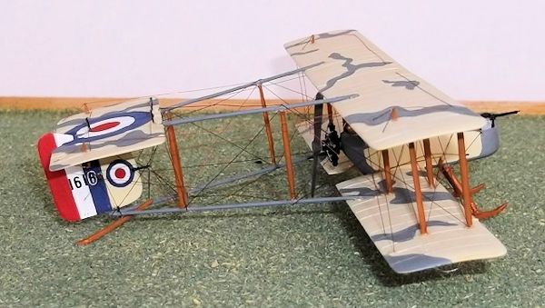
booms are light grey and the struts light brown. I hand painted the rudder
stripes and cockades on the wings, tail surface and the fin: you could use the
under wing cockades from the DH 4 or use another suitable source if you have
them. The fin roundels are very small and the one on the tail is an awkward size
too and as I do not know of any source for these I hand painted them. I think
that the underwing roundels should probably be inboard of the ailerons, as
photos of aircraft from 5 Squadron show them there, but I mistakenly painted
mine towards the tips. Oh well! The serial on the rudder came from dry rub down
transfers: I painted the white outlines.
pattern is not clear. I used
light grey but it could have been dark earth according to some sources. I think
that it could also have been PC 8 a kaki colour used on the upper surfaces of
aircraft before PC 10. I did not put camouflage on the fuselage sides, but I
have no direct evidence that it was not applied. The fuel tank is copper, the
booms are light grey and the struts light brown. I hand painted the rudder
stripes and cockades on the wings, tail surface and the fin: you could use the
under wing cockades from the DH 4 or use another suitable source if you have
them. The fin roundels are very small and the one on the tail is an awkward size
too and as I do not know of any source for these I hand painted them. I think
that the underwing roundels should probably be inboard of the ailerons, as
photos of aircraft from 5 Squadron show them there, but I mistakenly painted
mine towards the tips. Oh well! The serial on the rudder came from dry rub down
transfers: I painted the white outlines.
| FINAL CONSTRUCTION |
Now complete the assembly of the model. I used the wing struts from the DH 4.
Start by cementing the four outer struts in the holes on the underside of the
upper wing, then place small blobs of glue into the outer holes on the lower
wing and carefully lower the top wing and struts into the holes on the lower
wing, and fit the rudder by putting the rudder posts into the V of the lower
boom and the V of the horizontal tail unit. Secure the rudder posts with glue.
Align the wings and struts so that all is square, and support the wings and
 booms while this dries out. When it is dry you can carefully handle the
structure to be able to measure the lengths of the inner wing and fuselage
struts with a pair of dividers. If necessary cut the struts to the correct
length and measure them again to make sure that you have done this accurately.
Glue the wing and fuselage struts into place. You will need to support the top
wing and booms again while these dry. When they are set you can measure the
lengths of the boom struts with a pair of dividers and cut them from card or use
struts from the Avro 504 before glueing into position. Be careful with this
assembly as it is a bit fragile while under construction, but when it is
completed and has dried out properly it is fairly rigid. The undercarriage was
made from 20 thou plastic card shaped to aerofoil section. The skids were also
made from card. Drill small holes into the tops of the skids and then glue the
axle to the skids and set aside to dry thoroughly. When it is ready glue the
legs into the holes in the top of the skids, and cement the tops of the legs
into small holes drilled in the bottom of the nacelle. This will also need to be
supported while it dries out. Now paint the struts and skids a light wood, wheel
tyres dark grey and wheel discs clear doped linen. Glue on the wheels. Cut and
fit control horns on the fuselage, and horns for the elevators, ailerons and
rudder, and paint light brown. Wing skids were from 5 amp fuse wire bent to the
correct shape. Finish any other painting or touching in.
booms while this dries out. When it is dry you can carefully handle the
structure to be able to measure the lengths of the inner wing and fuselage
struts with a pair of dividers. If necessary cut the struts to the correct
length and measure them again to make sure that you have done this accurately.
Glue the wing and fuselage struts into place. You will need to support the top
wing and booms again while these dry. When they are set you can measure the
lengths of the boom struts with a pair of dividers and cut them from card or use
struts from the Avro 504 before glueing into position. Be careful with this
assembly as it is a bit fragile while under construction, but when it is
completed and has dried out properly it is fairly rigid. The undercarriage was
made from 20 thou plastic card shaped to aerofoil section. The skids were also
made from card. Drill small holes into the tops of the skids and then glue the
axle to the skids and set aside to dry thoroughly. When it is ready glue the
legs into the holes in the top of the skids, and cement the tops of the legs
into small holes drilled in the bottom of the nacelle. This will also need to be
supported while it dries out. Now paint the struts and skids a light wood, wheel
tyres dark grey and wheel discs clear doped linen. Glue on the wheels. Cut and
fit control horns on the fuselage, and horns for the elevators, ailerons and
rudder, and paint light brown. Wing skids were from 5 amp fuse wire bent to the
correct shape. Finish any other painting or touching in.
Rigging.
I recommend either stretched sprue or very thin wire for the rigging. Measure
each length of wire or sprue on the model using a pair of dividers and glue into
place with either superglue (wire) or liquid cement (sprue). This model has well
over 100 individual strands so it will take a long time and you need to be
patient. So as not to leave any wires out (easily done), start with the wires
between the fuselage struts, then the rear wires of the wings, and the fore-aft
wires between the wing struts. Now glue on the engine and propellor.
 Run control
wires from the control horns on the fuselage to the rear of the fuselage, and
finish the wings. Then rig the booms starting from the front, and then the tail.
Add the short wires from the control horns to the trailing edges of the
ailerons, elevators and rudder, and from the tail unit control surfaces to the
rear of the wings. Finally put on the anti-drag wires from the booms to the rear
outer struts and from the front of the nacelle to the front struts. This
sequence will hopefully reduce your chances of damaging work already done and
the risk of missing out any wires. Add a tail skid, cut and shaped from card and
painted light brown, with a small hole drilled in the top surface to glue to the
bottom of the rudder post which should extend beneath the lower boom, and add
the small spring to the post on the leading edge of the fin from stretched sprue.
Glue a small length of stretched sprue to the front inner strut on the port
(left) side to represent the pitot tube and add a Lewis machine gun from the DH
4 to a post in the front cockpit.
Run control
wires from the control horns on the fuselage to the rear of the fuselage, and
finish the wings. Then rig the booms starting from the front, and then the tail.
Add the short wires from the control horns to the trailing edges of the
ailerons, elevators and rudder, and from the tail unit control surfaces to the
rear of the wings. Finally put on the anti-drag wires from the booms to the rear
outer struts and from the front of the nacelle to the front struts. This
sequence will hopefully reduce your chances of damaging work already done and
the risk of missing out any wires. Add a tail skid, cut and shaped from card and
painted light brown, with a small hole drilled in the top surface to glue to the
bottom of the rudder post which should extend beneath the lower boom, and add
the small spring to the post on the leading edge of the fin from stretched sprue.
Glue a small length of stretched sprue to the front inner strut on the port
(left) side to represent the pitot tube and add a Lewis machine gun from the DH
4 to a post in the front cockpit.
| CONCLUSIONS |
I had not made a model in three decades, so I made a couple first before I attempted to finish this, including the Airfix 0/400 so that I had some recent experience to draw on. Much of the work had been done when I found this in the roof after 30+ years: I had to paint it and finish the assembly. I do not recommend it for a first attempt at a biplane conversion, but if you have already done some conversions or scratch building of WW1 aircraft this should not prove to be too difficult. Moulding your own parts is easier than it sounds - I had to mould a wing section for the 0/400, and I have posted a full article on this on the Airfix Tribute Forum. The most difficult sections on this model were getting the booms at the right angle, and the rigging, but I managed it even though my patience was tested, sometimes nearly to destruction! This is quite a long build but the result is worth it because you will have an under-represented aircraft in your model collection. People even ask me if this was from a kit: it is nice to be able to say no.
| REFERENCES |
The best
source is the Windsock DataFile No 56 by Albatross Publications: there are good
plans in there.
Warplanes of the First world War: Fighters Vol. 3 by J.
M.Bruce was also used, as was
The British Fighter Since 1912 by P. Lewis and
Fighters 1914 -1919
by K. Munson.
There is an
article on making parts using the moulding technique described here in
www.airfixtributeforum/top-tips-and-techniques .
May 2013
If you would like your product reviewed fairly and fairly quickly, please contact the editor or see other details in the Note to Contributors.