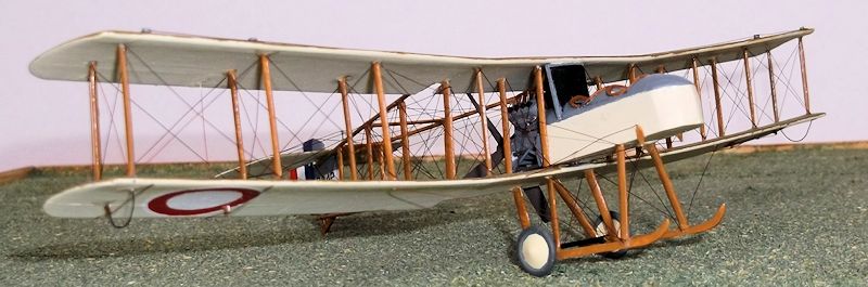
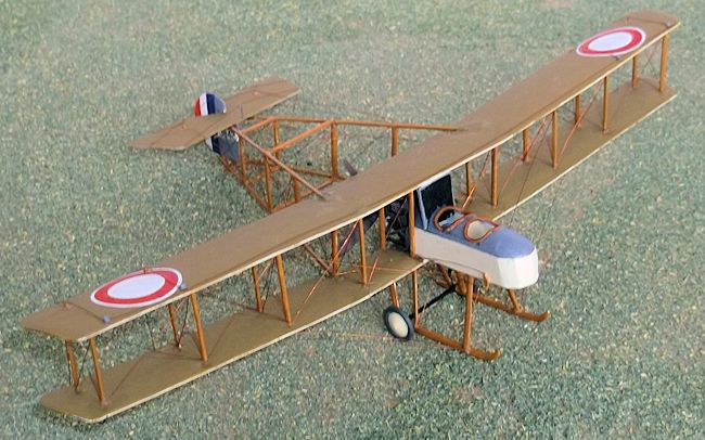
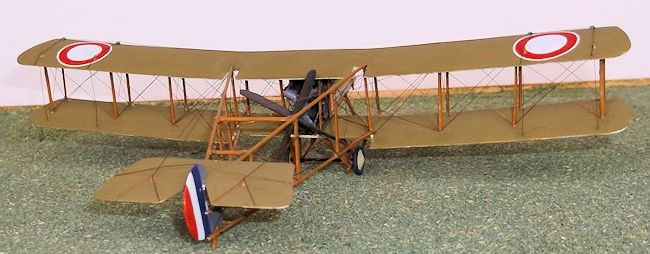
1/72 Sopwith Type 806 Gunbus
| KIT #: | 01048 |
| PRICE: | £5.00 |
| DECALS: | One option |
| REVIEWER: | Stephen Foster |
| NOTES: |
Conversion using two kits |
This aeroplane, which
looked almost like a fossil bird, was a result of the request for a
two-seat anti-submarine patrol aircraft from the Greek Admiralty, and
was originally to have been a floatplane. It was one of the first of T.
Sopwith's aircraft to be designed specifically for military use: an
order for three with dual controls was placed by the Greek government in
1913, with a second order for six being placed in February 1914. These
were delivered as land planes with a four-wheel undercarriage between
July and October 1914, but most were commandeered by the British
Admiralty for use by the Royal Navy Air Service (RNAS). These were
numbered 801 - 806 and were named the Admiralty Type 806. In fact the
British Admiralty had ordered two machines in October 1913 and these
were delivered to the Isle of Grain in March 1914.
 The term
"gunbus" is frequently associated with the Vickers FB5 and FB9 fighting
biplanes, but it was a generic term used at the time to describe any
armed scout or reconnaissance aircraft. The pusher design was adopted
because there was a lack of a reliable interrupter gear which would stop
the pilot from shooting off his own propeller. Instead the
observer/gunner had a wide field of fire and in the case of the Sopwith
Gunbus a 0.303 inch Lewis machine gun was sometimes mounted on a
telescopic pillar.
The term
"gunbus" is frequently associated with the Vickers FB5 and FB9 fighting
biplanes, but it was a generic term used at the time to describe any
armed scout or reconnaissance aircraft. The pusher design was adopted
because there was a lack of a reliable interrupter gear which would stop
the pilot from shooting off his own propeller. Instead the
observer/gunner had a wide field of fire and in the case of the Sopwith
Gunbus a 0.303 inch Lewis machine gun was sometimes mounted on a
telescopic pillar.
| CONSTRUCTION |
Like many other
little-known early aircraft types there is no model of this aircraft
produced in 1/72 scale, although card models in 1/48 and 1/50 scales are
available. The only reference to a conversion that I know of was by G.
Scarborough published in Airfix Magazine Annual No 5 in 1975 and I used
this as the basis for my model. G. Scarborough did not build a full
aircraft as his was part of a small diorama with the aeroplane partly
dismantled and being towed on a trailer, as illustrated in a series of
photographs of
 Robey
built machines being taken from the factory in Lincoln to a nearby
testing field. In this diorama the wings and horizontal tail unit were
carried in the towing lorry. I have chosen to represent the entire
aircraft without any vehicles. There are two (possibly more) kits that
could be used as starting points: the Airfix Avro 504 (as in my model),
or the Airfix DH 4, both of which could provide wings, wheels, struts,
etc, but in either case you will need two kits unless you are prepared
to make part of the wings from card. I used G. Scarborough's method of
increasing the chord of the Avro 504 wings and kept the fuselages for
later use to correct the errors in that kit when I make different
variants of that famous type. The engines and propellors also proved
useful for the conversions of Vickers Gunbuses from D H 4's: it is
surprising how much of a kit can be used in different conversions.
Robey
built machines being taken from the factory in Lincoln to a nearby
testing field. In this diorama the wings and horizontal tail unit were
carried in the towing lorry. I have chosen to represent the entire
aircraft without any vehicles. There are two (possibly more) kits that
could be used as starting points: the Airfix Avro 504 (as in my model),
or the Airfix DH 4, both of which could provide wings, wheels, struts,
etc, but in either case you will need two kits unless you are prepared
to make part of the wings from card. I used G. Scarborough's method of
increasing the chord of the Avro 504 wings and kept the fuselages for
later use to correct the errors in that kit when I make different
variants of that famous type. The engines and propellors also proved
useful for the conversions of Vickers Gunbuses from D H 4's: it is
surprising how much of a kit can be used in different conversions.
Start by
making the fuselage nacelle. This was built from 20 thou card sides and
floor with three bulkheads, one at the point where the top decking
starts to curve at the nose end, one between the cockpits and one at the
rear. Construct a three sided box with the sides, floor and bulkheads
and add any cockpit detail including seats, and a control column, rudder
bar, etc in the front cockpit. The top decking was from 20 thou card
bent over the curved tops of the bulkheads and glued into place with
liquid cement. Cut a slot 20 thou wide in the top decking, 2mm behind
the rear cockpit to take the radiator which was made from card 11mm x
12mm with the surfaces scored to represent the radiator grill. The nose
of the nacelle was built up with scrap plastic and then covered with
filler and sanded to shape. The coamings around the cockpits were made
from thin rod or stretched sprue. The engine bearers were 15mm lengths
of rod inserted into holes drilled into the rear of the nacelle. The
rear support for the engine was cut from 20 thou card and cemented to
the rear ends of the engine bearer rods. Thin rod or sprue made the
 additional
arms of the bearers, and card was used for the brackets at the front
end. The nacelle and engine bearers were painted before the engine was
cemented into place. Drill two holes under the nacelle to take the
undercarriage legs.
additional
arms of the bearers, and card was used for the brackets at the front
end. The nacelle and engine bearers were painted before the engine was
cemented into place. Drill two holes under the nacelle to take the
undercarriage legs.
The
engine was difficult to make as I could not find any good quality photos
or drawings: the drawings provided in the AM Annual were poor and not
very accurate but were among the better ones that I could find, so they
provided the basis for my efforts. Make the cylinder blocks from two
pieces of 60 thou laminated card with the ends rounded off. The engine
block/sump was also made from two pieces of 60 thou card, with a 20 thou
piece sandwiched between them. When this was dry I sanded to shape the
bottom and rear end, making sure that it fitted snugly into the space
between the engine bearers. The top of the engine block should slope
inwards to take the cylinder blocks. Drill a hole in the rear of the
engine block for the propellor. Assemble the cylinders to the engine
block and then add the exhaust pipes from short pieces of rod bent to a
curve. I put some very thin rod on the sides of the block to represent
pipes, and other tiny details as my imagination allowed. The assembly
was painted light grey with a little silver mixed in to give a metallic
finish. When the engine is finished cement the radiator to the nacelle
and the engine to the bearers, and then add the water pipes from the
cylinders to the radiator. I painted the water pipes copper with some
brown mixed in to take off the sheen. The exhaust pipes were rust. The
propellor blades were wide and had to be made from card and glued to the
boss of an old Camel(?) propellor which I found in the bottom of my
spares box which had had the original blades removed. (Why I had kept
this item I cannot remember: such are my hoarding tendencies). The
propellor was painted dark wood with a grey boss.
 piece
4.9 cm long. Cut a similar length from the starboard(right) side of the
lower wing. These will form the centre sections of the new wings.
Finally cut two lengths 1.1 cm long from what is left of the inner
sections of the lower wing.
piece
4.9 cm long. Cut a similar length from the starboard(right) side of the
lower wing. These will form the centre sections of the new wings.
Finally cut two lengths 1.1 cm long from what is left of the inner
sections of the lower wing.
 cut
and file shallow grooves on the top of the trailing edges of the wings
where the booms will be joined later. Strictly this is not accurate as
the booms were inserted into the rear of the wings but this is not
really practical on this model as the wings are so thin that the
resulting joint would be very weak.
cut
and file shallow grooves on the top of the trailing edges of the wings
where the booms will be joined later. Strictly this is not accurate as
the booms were inserted into the rear of the wings but this is not
really practical on this model as the wings are so thin that the
resulting joint would be very weak.
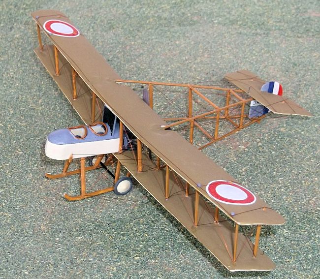
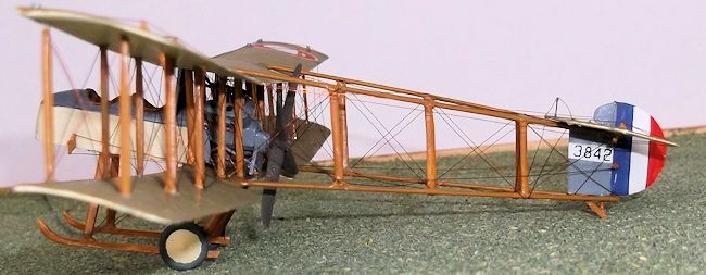
| COLORS & MARKINGS |
 Markings
on these machines varied greatly as photographs show, so select the
machine you wish to model and use the photos to guide you. I based mine
on 3842 as it probably appeared in late 1915: photos of at least one,
possibly two machines show them with RNAS roundels under the wing tips
and rudder stripes and I assume that 3842 had similar markings. I
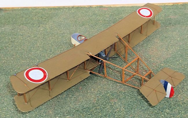
painted RNAS roundels on the upper wings: the photos clearly show the
white outer rings. To hand paint roundels scribe the outer circle with a
pair of dividers and then paint the inside of the circle white. When
this is dry scribe two concentric circles, again with the dividers, for
the red ring and then paint this. The paint will run into the grooves
made by the dividers and give you a nice clean edge, but you will need a
fine brush, a steady hand and thin paint. You may need to use two coats
of paint especially for the white. Alternatively you could use RNAS
roundels from the Pegasus transfer sheet early RNAS roundels and flags
(PGS 72 001) which I managed to find only after I had completed my
model. I also painted the white stripe on the fin for the serial but
whether this survived in service I cannot be sure. The serial came from
dry rub-down transfers and the rudder stripes were hand painted.
Markings
on these machines varied greatly as photographs show, so select the
machine you wish to model and use the photos to guide you. I based mine
on 3842 as it probably appeared in late 1915: photos of at least one,
possibly two machines show them with RNAS roundels under the wing tips
and rudder stripes and I assume that 3842 had similar markings. I
painted RNAS roundels on the upper wings: the photos clearly show the
white outer rings. To hand paint roundels scribe the outer circle with a
pair of dividers and then paint the inside of the circle white. When
this is dry scribe two concentric circles, again with the dividers, for
the red ring and then paint this. The paint will run into the grooves
made by the dividers and give you a nice clean edge, but you will need a
fine brush, a steady hand and thin paint. You may need to use two coats
of paint especially for the white. Alternatively you could use RNAS
roundels from the Pegasus transfer sheet early RNAS roundels and flags
(PGS 72 001) which I managed to find only after I had completed my
model. I also painted the white stripe on the fin for the serial but
whether this survived in service I cannot be sure. The serial came from
dry rub-down transfers and the rudder stripes were hand painted.
| FINAL CONSTRUCTION |
 more
drops of glue on to the tops of the nacelle struts and run a little
along the top of the radiator and then gently lower the top wing so that
the leading edge of the top wing aligns with the edge of the radiator
and the nacelle struts enter the holes on the underside of the wing. The
pin on the bottom of the fin should drop into the apex of the V of the
lower boom: it can be glued with superglue. Although this structure
sounds weak it is stronger than you might think! Carefully cement two
struts into the outer holes of both sides of the wings: these came from
one of the 504's and should be the correct size without needing
adjustment. This sub-assembly can now be allowed to dry thoroughly and
you can go off and have a celebratory drink and relax as the most
difficult part is now over. Although this assembly will not stand rough
handling, when dry it can be manipulated sufficiently for the remaining
wing and the boom struts to be inserted with few problems. When it is
dry the remaining four struts from the second 504 kit can be inserted
into the wings and the rest either raided from the spares box or made
and shaped from card. The boom struts were made from card and inserted
using superglue to hold them in place. I inserted at least two sets of
boom struts before finishing the wings simply to make the structure a
little stronger. When the assembly is complete it is much stronger than
you think, but I do not recommend any test flights!
more
drops of glue on to the tops of the nacelle struts and run a little
along the top of the radiator and then gently lower the top wing so that
the leading edge of the top wing aligns with the edge of the radiator
and the nacelle struts enter the holes on the underside of the wing. The
pin on the bottom of the fin should drop into the apex of the V of the
lower boom: it can be glued with superglue. Although this structure
sounds weak it is stronger than you might think! Carefully cement two
struts into the outer holes of both sides of the wings: these came from
one of the 504's and should be the correct size without needing
adjustment. This sub-assembly can now be allowed to dry thoroughly and
you can go off and have a celebratory drink and relax as the most
difficult part is now over. Although this assembly will not stand rough
handling, when dry it can be manipulated sufficiently for the remaining
wing and the boom struts to be inserted with few problems. When it is
dry the remaining four struts from the second 504 kit can be inserted
into the wings and the rest either raided from the spares box or made
and shaped from card. The boom struts were made from card and inserted
using superglue to hold them in place. I inserted at least two sets of
boom struts before finishing the wings simply to make the structure a
little stronger. When the assembly is complete it is much stronger than
you think, but I do not recommend any test flights!
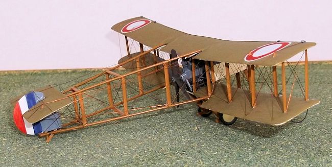
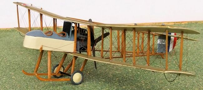
 Now for
the fun part; rigging. There are about 140 individual wires to be put on
to this model (more than any other that I have made, and compared with
just over 50 on the DH 4), so expect it to take some time to complete.
Start by rigging the front to rear wires between the wing struts,
working from the centre outwards. Then rig the rear of the wings
followed by the front. The sides of the booms are next and when the rear
bays of the booms have been rigged the horizontal tail surfaces can be
glued into place. Rig the horizontal wires between the booms but before
you complete the forward bays put on the propellor. The undercarriage is
next and then the control wires on the wings and tail, the control wires
from the horns on the nacelle to the struts, and the tail bracing.
Finally add the elevator and rudder wires, the anti drag wires, and the
balance wire along the leading edge of the top wing. The tail skid and
wing skids (the latter made from 5 amp fuse wire) complete the model.
Now for
the fun part; rigging. There are about 140 individual wires to be put on
to this model (more than any other that I have made, and compared with
just over 50 on the DH 4), so expect it to take some time to complete.
Start by rigging the front to rear wires between the wing struts,
working from the centre outwards. Then rig the rear of the wings
followed by the front. The sides of the booms are next and when the rear
bays of the booms have been rigged the horizontal tail surfaces can be
glued into place. Rig the horizontal wires between the booms but before
you complete the forward bays put on the propellor. The undercarriage is
next and then the control wires on the wings and tail, the control wires
from the horns on the nacelle to the struts, and the tail bracing.
Finally add the elevator and rudder wires, the anti drag wires, and the
balance wire along the leading edge of the top wing. The tail skid and
wing skids (the latter made from 5 amp fuse wire) complete the model.
| CONCLUSIONS |
July 2014
Copyright ModelingMadness.com. All rights reserved. No reproduction in any form without express permission from the editor. If you would like your product reviewed fairly and fairly quickly, please
contact
the editor or see other details in the
Note to
Contributors.