Special Hobby 1/48 Nieuport 10
| KIT #: | 48184 |
| PRICE: | $40.00 |
| DECALS: | Three options |
| REVIEWER: | Rob Hart |
| NOTES: |
| HISTORY |
The aircraft that would become the Nieuport 10 was designed
by Gustave Delage to compete in the 1914 Gordon Bennett Cup. Before the race
took place World War One began and Delage was recalled to the navy. Delage was
released from the navy in early 1915 and began adapting the design for military
purposes. To that end several modifications were made before the aircraft went
into production. The lower wing was reduced in span and the leading edge at the
root was cut 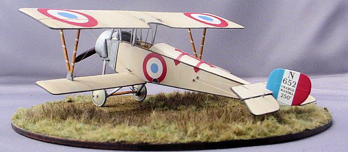 back
to allow greater visibility. A revised tailplane and elevators along with a
slightly enlarged rudder were also fitted. Initially the observer occupied the
front seat and the pilot the rear, but later models transposed the crew
positions. Eventually many Nieuport 10s would be converted to single seaters (a
1/48 single seater kit is also available from Special Hobby) and flown from what
had been the rear seat. France, Great Britain, and Belgium awarded production
contracts for Nieuport 10s and deliveries began in May of 1915. The type was
also license built by Italy and Russia. The exact number of Nieuport 10s built
by all production sources is unknown, but the type served on all major fronts in
World War One and was used postwar by Finland. Many French aces scored their
earliest aerial victories while flying the Nieuport 10. Pilots flying it also
accounted for Belgium and Canada's initial aerial victories and a British pilot,
Richard Bell-Davies, was awarded the Victoria Cross for action taken while
flying a Nieuport 10
back
to allow greater visibility. A revised tailplane and elevators along with a
slightly enlarged rudder were also fitted. Initially the observer occupied the
front seat and the pilot the rear, but later models transposed the crew
positions. Eventually many Nieuport 10s would be converted to single seaters (a
1/48 single seater kit is also available from Special Hobby) and flown from what
had been the rear seat. France, Great Britain, and Belgium awarded production
contracts for Nieuport 10s and deliveries began in May of 1915. The type was
also license built by Italy and Russia. The exact number of Nieuport 10s built
by all production sources is unknown, but the type served on all major fronts in
World War One and was used postwar by Finland. Many French aces scored their
earliest aerial victories while flying the Nieuport 10. Pilots flying it also
accounted for Belgium and Canada's initial aerial victories and a British pilot,
Richard Bell-Davies, was awarded the Victoria Cross for action taken while
flying a Nieuport 10
| THE KIT |
 The kit
includes 64 plastic parts, a small fret of photo etched parts, one resin part,
an acetate windscreen, a large decal sheet, and an eleven page color instruction
booklet. I categorize the quality of the plastic parts as 'limited run'. There
is flash, evidence of mold shift, and many of the small detail parts are thick
and crude. I was surprised by the mediocre quality of the plastic parts. The kit
was released in 2016 and other recently released Special Hobby kits don't give
up much to mainstream manufacturers products in terms of the crispness of the
moldings. I suspect the tooling dates to much earlier than the release date. The
5.5” x 7” decal sheet has markings for one each French, British, and Belgian
aircraft. The French and British examples are clear doped linen and the Belgian
machine is finished in an off white dope overall. The photo etched fret includes
turnbuckles, control horns, instrument gauge faces, breather pipe opening
surrounds, seat belts, a throttle quadrant, engine push rods, and landing gear
details. The sole resin part is a pitot tube for the Belgian option.
The kit
includes 64 plastic parts, a small fret of photo etched parts, one resin part,
an acetate windscreen, a large decal sheet, and an eleven page color instruction
booklet. I categorize the quality of the plastic parts as 'limited run'. There
is flash, evidence of mold shift, and many of the small detail parts are thick
and crude. I was surprised by the mediocre quality of the plastic parts. The kit
was released in 2016 and other recently released Special Hobby kits don't give
up much to mainstream manufacturers products in terms of the crispness of the
moldings. I suspect the tooling dates to much earlier than the release date. The
5.5” x 7” decal sheet has markings for one each French, British, and Belgian
aircraft. The French and British examples are clear doped linen and the Belgian
machine is finished in an off white dope overall. The photo etched fret includes
turnbuckles, control horns, instrument gauge faces, breather pipe opening
surrounds, seat belts, a throttle quadrant, engine push rods, and landing gear
details. The sole resin part is a pitot tube for the Belgian option.
| CONSTRUCTION |
Construction started with the cockpit. The kit has
upper (flush with the cockpit sill) and lower longerons and vertical uprights
molded onto the interior fuselage sides. Plastic parts are also provided to
represent an oil tank, fuel tank (which the rear seat sits on top of), joystick,
floor, rudder bar, and front seat mount. Ledges are molded onto the interior of
the right fuselage half where the floor and fuel tank are to be attached. The
floor is represented by a trapezoidal shaped part with the pilot's foot guides,
rudder bar mount, and joystick socket molded integrally. The real cockpit did
not have a floor, instead, the joystick, rudder bar, foot guides, and front seat
mount were attached to wood cross members that spanned the interior width of the
fuselage and attached to the uprights. Not wanting to add a lot of detail that
probably couldn't be seen after the front seat was installed and the fuselage
closed, I opted for a compromise. I filed off the ledge on the interior fuselage
side where the floor was supposed to attach and I filed off the sides of the
floor part flush with the outer edges of the pilot's foot guides. I fabricated
cross members from lengths of .020 x .020 styrene strip which I glued to the
bottom of the modified floor part corresponding to the locations of the uprights
molded on the interior of the fuselage halves and attached the ends of the cross
members to the uprights midway between the bottom of the fuselage and the
cockpit sill. I replaced the clunky kit seats with photo etched examples from an
Eduard WW1 seats set and used seat belts from an Eduard WW1 French seat belt
set. I also made seat cushions from two part epoxy putty. I used a dull #11
blade to press grooves into the not quite cured putty in a cross hatched pattern
to simulate tufting and graced the tufts with buttons that I pressed out of .010
sheet styrene with a miniature punch and die set. The buttons were placed at the
intersections of the corners of thetufts. To simulate worn leather I painted the
seat cushions with Tamiya acrylic brown and dry brushed them with Testors tan
enamel. Nieuport 10s did not have instrument panels. The instrument cases were
simply attached to the uprights atseemingly
 random
locations . The kit provided photo etched instrument gauge faces with tabs on
one side where they are to be glued to the uprights. I didn't like the 2
dimensional look of the photo etched gauge faces so I replaced them with new
parts. I madeinstrument cases punched out of 020 sheet styrene with a miniature
punch and die set that I attached to gauge faces from an Eduard WW1 instruments
set. The new parts represented a temperature gauge, a clock, a tachometer, an
altimeter, and a compass. After I attached the new instrument cases to the
uprights I glued one end of Detail Master black detail wires to holes drilled in
the backs of the instrument cases and ran the other ends of the wires out of
sight under and behind the back of the oil tank. I painted the interior of the
fuselage halves with a Tamiya acrylic paint mix for clear doped linen (9 x X2
white + 1 x X60 dark yellow). I masked off the parts of the fuselage interior
that would represent clear doped linen leaving the uprights, longerons, and
forward 1/3 of the bottom of the fuselage exposed. I applied a streaky burnt
umber oil paint wash to the unmasked areas which after drying for a few days
were over sprayed with a 70/30 mix of Tamiya acrylic Clear Yellow and Clear
Orange to simulate varnished wood. I repeated the simulated wood technique on
the seats and cockpit floor. In WW1 the French painted the metal fittings of
their aircraft with a color called “Horizon Blue”. I painted the oil tank, fuel
tank, joystick, front seat mount, and rudder bar with a Tamiya acrylics mix for
“Horizon Blue” (1 x XF18 Medium Blue + 1 x XF2 White). Finally, I painted the
areas on the interior sides of the forward fuselage corresponding with the metal
panels molded on the exterior with Alclad aluminum. Then I made interior bracing
rigging from .004 stainless steel music wire and ran them diagonally from the
junctions of the longerons and uprights .. Finally I attached all of the various
cockpit components except the seats to their positions on the fuselage halves
and glued the fuselage halves together.
random
locations . The kit provided photo etched instrument gauge faces with tabs on
one side where they are to be glued to the uprights. I didn't like the 2
dimensional look of the photo etched gauge faces so I replaced them with new
parts. I madeinstrument cases punched out of 020 sheet styrene with a miniature
punch and die set that I attached to gauge faces from an Eduard WW1 instruments
set. The new parts represented a temperature gauge, a clock, a tachometer, an
altimeter, and a compass. After I attached the new instrument cases to the
uprights I glued one end of Detail Master black detail wires to holes drilled in
the backs of the instrument cases and ran the other ends of the wires out of
sight under and behind the back of the oil tank. I painted the interior of the
fuselage halves with a Tamiya acrylic paint mix for clear doped linen (9 x X2
white + 1 x X60 dark yellow). I masked off the parts of the fuselage interior
that would represent clear doped linen leaving the uprights, longerons, and
forward 1/3 of the bottom of the fuselage exposed. I applied a streaky burnt
umber oil paint wash to the unmasked areas which after drying for a few days
were over sprayed with a 70/30 mix of Tamiya acrylic Clear Yellow and Clear
Orange to simulate varnished wood. I repeated the simulated wood technique on
the seats and cockpit floor. In WW1 the French painted the metal fittings of
their aircraft with a color called “Horizon Blue”. I painted the oil tank, fuel
tank, joystick, front seat mount, and rudder bar with a Tamiya acrylics mix for
“Horizon Blue” (1 x XF18 Medium Blue + 1 x XF2 White). Finally, I painted the
areas on the interior sides of the forward fuselage corresponding with the metal
panels molded on the exterior with Alclad aluminum. Then I made interior bracing
rigging from .004 stainless steel music wire and ran them diagonally from the
junctions of the longerons and uprights .. Finally I attached all of the various
cockpit components except the seats to their positions on the fuselage halves
and glued the fuselage halves together.
The kit engine is reasonable in shape and detail, but
has webs of flash between the cylinder heads that extend into the tiny gaps
between the cooling fins. It also uses photo etched parts to represent the push
rods. I didn't like the appearance of the flat photo etched push rods and I
wasn't looking forward to the tedious clean up needed to get rid of the flash
fouling the spaces between the cooling fins. I decided to replace the kit engine
with a resin Vector Le Rhone 9C that I happened to have on hand. The Vector
engine has the crankcase, cylinder heads, induction pipes, and push rods all
cast separately. I replaced the resin push rods with lengths of .012 stainless
steel music wire. I had yet to use a Vector engine that would drop fit inside of
a kit's cowling and this one was no exception. I ground out the interior of the
cowling with a Dremel until it was tran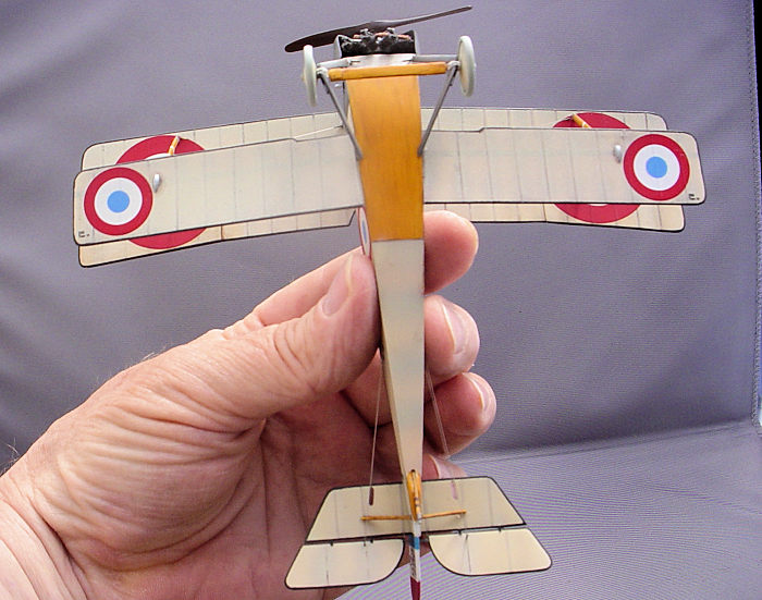 slucent
when held up to a light before the engine would just barely fit inside. I
painted the crankcase and cylinder heads with Alclad steel and painted the
induction pipes with Alclad copper. I left the push rods unpainted. After I
assembled all of the various engine components I placed the completed sub
assembly inside a small sealed jar to protect it from being accidentally damaged
during the rest of the building process.
slucent
when held up to a light before the engine would just barely fit inside. I
painted the crankcase and cylinder heads with Alclad steel and painted the
induction pipes with Alclad copper. I left the push rods unpainted. After I
assembled all of the various engine components I placed the completed sub
assembly inside a small sealed jar to protect it from being accidentally damaged
during the rest of the building process.
After sanding the fuselage seam smooth, I drilled out all of the rigging attachment locations with a #80 drill bit using the kit's accurate and complete rigging guide. I also drilled out all of the strut attachment locations and all of the strut ends. I replaced the plastic pins on the strut ends with short lengths of .012 stainless steel music wire. My experience with the tiny plastic pins on load baring struts in recently tooled WW1 aircraft kits is that after being glued (especially if glued with solvent based glue) they are prone to failure. I prefer to head off the potential failures by replacing the plastic pins with steel wires.
The lower wings attach to the fuselage with a pin and socket arrangement. The pins on the wing roots are only about 1/16” long. I had doubts that the join would be strong enough to survive the handling required to finish the model, but went ahead and glued the wings to the fuselage with Tamiya Extra Thin cement. My doubts were realized when both wings repeatedly fell off while I was trying to set the dihedral, It appeared that the cement had almost completely dissolved the styrene pins on the ends of the wings. I don't know if this was due to a flaw in the kit's styrene or if I used too much cement, but I decided to take steps to obtain a more rigid and permanent join. I drilled out the pin locations on the wing roots and inserted short lengths of 1/16” diameter steel pins. I then attached the wings to the fuselage with slow setting cyanoacrylate glue.
| COLORS & MARKINGS |
 ts
surrounding the exit openings in the fuselage for the control lines. The French
either painted or taped the edges of the flying surfaces and the edges of the
fuselages of early Nieuports. The exact color(s) used has not been conclusively
determined, but the consensus is that it was most likely black or horizon blue.
I masked off all of the wings, tail planes, and the fabric covered portions of
the fuselage except for 1 mm wide strips outlining the edges and sprayed the
strips Tamiya Nato Black. In WW1, the French over coated their wood propellers
with a fairly opaque maroon colored varnish. I re-created this by applying the
simulated wood effect and then applying multiple coats of a mix of Tamiya Clear
Red and Clear Blue (I don't recall the exact ratio, but I think it was around 30
parts of Clear Red to 1 part of Clear Blue).
ts
surrounding the exit openings in the fuselage for the control lines. The French
either painted or taped the edges of the flying surfaces and the edges of the
fuselages of early Nieuports. The exact color(s) used has not been conclusively
determined, but the consensus is that it was most likely black or horizon blue.
I masked off all of the wings, tail planes, and the fabric covered portions of
the fuselage except for 1 mm wide strips outlining the edges and sprayed the
strips Tamiya Nato Black. In WW1, the French over coated their wood propellers
with a fairly opaque maroon colored varnish. I re-created this by applying the
simulated wood effect and then applying multiple coats of a mix of Tamiya Clear
Red and Clear Blue (I don't recall the exact ratio, but I think it was around 30
parts of Clear Red to 1 part of Clear Blue).
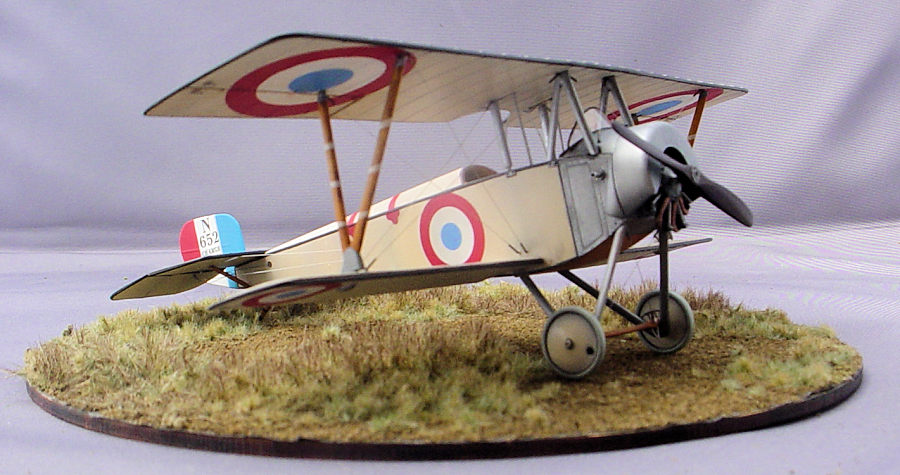
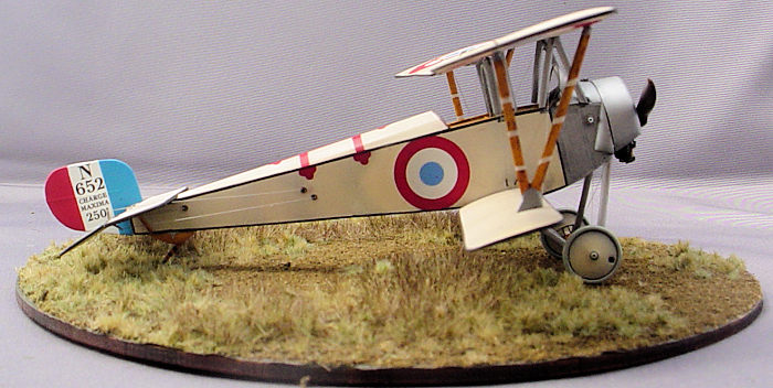
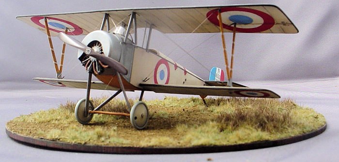
I chose to finish the model in decal option “A”, an unarmed aircraft assigned to Escadrille MF388 in Boresnica, Macedonia during December, 1916. The decals are perfectly registered, opaque, and even the tiniest stenciling is legible. They have very little decal film and lay down over surface details so well as to look painted on. However, they are diabolically difficult to apply. Once applied to a surface they do not like to be moved and have a penchant for folding over on themselves with no advance warning. I had experienced this previously and, despite taking every precaution, still had one of the blue roundel centers and one of the aircraft number/weight table stencils on the rudder fold up while I was trying to move them into position. Fortunately, Special Hobby provided separate decals for the rudders; one integrating the aircraft number/weight table stencil with the tricolor and one with just the stenciling. I had previously painted the tricolor on the rudder with Tamiya acrylics that I had mixed to match the colors of the decals. I was able to cut a new roundel center from the blue on the spare tricolor decal and cut the white portion of the tricolor decal that included the aircraft number/weight table stencil from the same spare decal. I was able to apply the rest of the decals without any more drama. Once the decals had dried, I applied a burnt umber oil paint pin wash in the recessed panel lines and the aileron/wing junctions and a dark gray oil paint wash over the natural metal areas. I dry brushed Testors Flat Aluminum enamel over the corners of the cowl and the raised detail on the natural metal areas. I applied a streaky wash of AK Interactive “Fuel Stains” on the forward 1” of the fuselage bottom and the upper one third of the landing gear struts to simulate unburned oil from the the rotary engine's total loss lubrication system. After all of the painting, decaling, and weathering was completed I sealed everything with a coat of Tamiya acrylic flat finish.
| FINAL CONSTRUCTION |
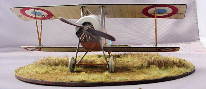
Final construction: I
assembled the landing gear and attached it to the fuselage. I simulated the
bungee cord suspension by winding lengths of Pro-Tech white detail wire around
the axle and through the lower ends of the landing gear struts. I formed the
acetate windshield to match the contour of the upper forward fuselage by
wrapping it around the handle of a JLC saw and passing it multiple times through
the steam coming from the spout of a boiling tea kettle. I attached the
windshield to the fuselage with white glue. I attached the seats to their mounts
in the cockpit with Gator's Grip acrylic glue and used the same adhesive to glue
the fuel and oil tank filler caps to the upper forward fuselage just behind the
cowl. Having completed all of the sub-assemblies that having the upper wing in
place would have made inaccessible I tried to attach the upper wing. I attache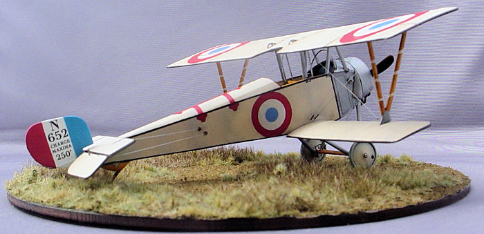 d
the upper wing and lower wings by the interplane struts, but this caused the
upper wing to have to much forward stagger and the cabane strut attachment
points on the upper wing were two mm forward of where they needed to be to
correctly line up with their attachment points on the fuselage. I decided to try
to correct the issue by moving the lower wings two mm toward the rear of the
fuselage. After moving the lower wings back all of the strut locations lined up
and I attached the upper wing. I rigged the model with .004 mm stainless steel
music wire and attached lengths of .03 mm brass tubing at the ends of the wires
to simulate turnbuckles. After finishing the rigging, I attached the engine,
cowl, wheels, horizontal stabilizers, elevators, rudder, tail skid, and
propeller. To finish the model, I added control lines from the same wire I had
used for the rigging and ran them from the holes in the sides of the rear
fuselage to photo-etched control horns on the stabilizers and rudder. I made a
display base with a circle cut from a Martin Welberg Scenic Studios “Rough
Meadow” grass mat that was glued to a pine disc seven inches in diameter.
d
the upper wing and lower wings by the interplane struts, but this caused the
upper wing to have to much forward stagger and the cabane strut attachment
points on the upper wing were two mm forward of where they needed to be to
correctly line up with their attachment points on the fuselage. I decided to try
to correct the issue by moving the lower wings two mm toward the rear of the
fuselage. After moving the lower wings back all of the strut locations lined up
and I attached the upper wing. I rigged the model with .004 mm stainless steel
music wire and attached lengths of .03 mm brass tubing at the ends of the wires
to simulate turnbuckles. After finishing the rigging, I attached the engine,
cowl, wheels, horizontal stabilizers, elevators, rudder, tail skid, and
propeller. To finish the model, I added control lines from the same wire I had
used for the rigging and ran them from the holes in the sides of the rear
fuselage to photo-etched control horns on the stabilizers and rudder. I made a
display base with a circle cut from a Martin Welberg Scenic Studios “Rough
Meadow” grass mat that was glued to a pine disc seven inches in diameter.
While checking over the model for any loose rigging or needed paint touch ups, I noticed that the gap between the upper and lower wings looked excessive. I measured the gap and compared it to the scale drawings in the Windsock Datafile. Sure enough, the gap on the model was around 1-1.5 mm too big. I don't know if this error was attributable to my relocating the lower wings or if the kit measurements were off more than I realized, but I was really frustrated that I hadn't noticed it prior to attaching the upper wing and rigging the model. In hindsight, what I should have done was reduce the length of the interplane struts and drill out new attBruce, achment points for them on the wings. Oh well, it's not the first time that I've made a mistake building a model and it most certainly won't be the last.
| CONCLUSIONS |
The kit leaves a lot to be desired, but if you want a 1/48 Nieuport 10 in your collection this is your only choice. Like all of my models, this one didn't turn out as nice as I had hoped, but I enjoyed building it and probably sharpened my skills in the process.
| REFERENCES |
Bruce, J.M., 1998, Nieuport 10-12, Windsock Datafile 68, Albatros Publications
9 September 2022
Copyright ModelingMadness.com. All rights reserved. No reproduction in part or in whole without express permission.
If you would like your product reviewed fairly and fairly quickly, please contact the editor or see other details in the Note to Contributors.