| KIT #: | |
| PRICE: | $ |
| DECALS: | None |
| REVIEWER: | Stephen Foster |
| NOTES: | Scratch-built |
| HISTORY |
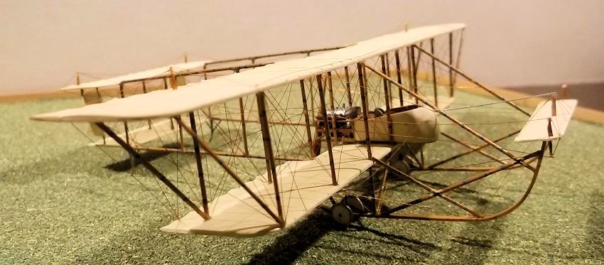
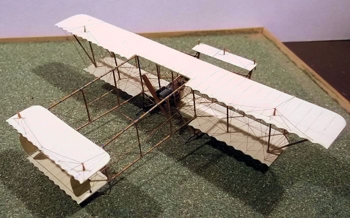
The Maurice Farman
MF 7 Longhorn was adopted by the RFC and RNAS in 1911 where it was used for
reconnaissance by 2, 4 and 6 squadrons (where it was known as the S7), and
training in the years leading to the First World War. Following the outbreak of
hostilities a few went to France where they were used for reconnaissance but
they were quickly withdrawn and from then on only used for training. The French
 continued using the type for front line duties until mid-1915. No armament was
carried by MF 7's.
continued using the type for front line duties until mid-1915. No armament was
carried by MF 7's.
This was a successful design which in civilian guise held a number of records including a distance record of 350 miles in a closed circuit in 1910, and successive duration records between 1911 and 1913. Most machines were built in France and equipped with 70 hp Renault engines, but some were built under licence in Bradford which were powered by 100 hp Sunbeams, and 47 others built in the UK were powered by 75 hp Rolls Royce Hawks. One aircraft was sold to Norway which survives in a museum in Oslo, and other machines are preserved in Paris and Brussels. Good photos of these machines can be found on wwi-models.org. These were invaluable as individual machines seemed to vary (there are notable differences in the preserved machines), but specific details are well shown in these photos. In particular the exhaust systems of the engines seemed to have varied, and some later aircraft had fold-down extensions of the upper main-planes, while others had narrow chord lower planes. I can only advise that modellers use whatever photos and other sources are available to them before they start: there does not seem to have been a "standard" machine.
| CONSTRUCTION |
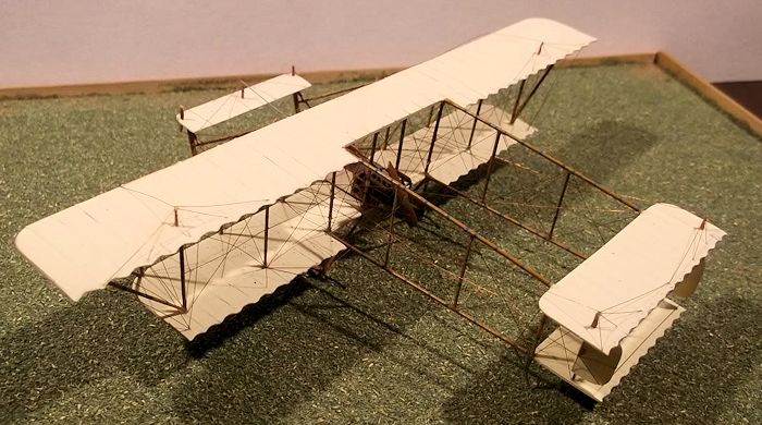
A 1/72 scale model has been issued by Lodemann but I have not seen one of these so I had to use my own resources. I started this on little more than a whim - I just happened to see it in Munson's Fighter and Training Aircraft 1914-1919. I assembled my own kit of plastic card, rod and Evergreen strip together with line drawings from finemodels.com which were reduced to 1/72 scale. This is a complete scratch build i.e. I have not used any parts from any other kit, although it would be possible to use wheels and perhaps a propellor from suitable sources.
I started with the
wings by cutting out two blanks from 40 thou card which I had previously bent in
a pipe using boiling water. I also cut out the tail surfaces from 40 thou card
but the front elevator and the rudders we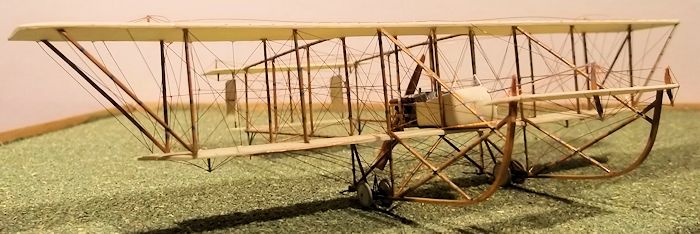 re from 30 the card. The trailing edges
of the wings, elevator and tail surfaces were thinned and the leading edges
rounded off. Holes were drilled in the wings and horizontal tail surfaces for
struts and undercarriage legs, and then ribs applied to the wings and horizontal
tail surfaces using 10 x 30 thou Evergreen strip glued with liquid cement. The
ribs were gently sanded to smooth the edges, the scallops in the trailing edges
shaped with a round file and sanded, and the ailerons scribed on.
re from 30 the card. The trailing edges
of the wings, elevator and tail surfaces were thinned and the leading edges
rounded off. Holes were drilled in the wings and horizontal tail surfaces for
struts and undercarriage legs, and then ribs applied to the wings and horizontal
tail surfaces using 10 x 30 thou Evergreen strip glued with liquid cement. The
ribs were gently sanded to smooth the edges, the scallops in the trailing edges
shaped with a round file and sanded, and the ailerons scribed on.
The nacelle was
plunge moulded from 30 thou card using the method that I have described before.
I made the nacelle longer than needed so that I could cut it to the exact length
when I was ready. I put in a seat for the pilot and observer, control column
with arms, a compass, control bar in front of the pilot, rudder bar, throttle
(right side of cockpit), etc - all of which will be very visible on the
completed model. The fuel tank was made from laminated card filed to shape. The
internal frames in the nacelle were from 10 x 10 thou Evergreen strip. I found a
drawing of a cockpit from a Flight Magazine of 1913 on the net which was very
helpful with these details. After the nacelle halves were glued together i
painted the interior and added the interior details. I drilled a hole in the
nose to take the elevator control rod and then trimmed the rear of the nacelle
before adding a piece of 30 thou card across the back, together with evergreen
strip to represent the frame. On the real machine this was wire mesh so I scored
some grooves on the rear face of the card which was then painted medium grey. I
also drilled a small hole under the rear of the nacelle and into the fuel tank
so that I put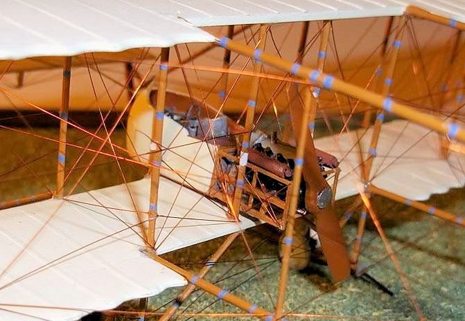 a short piece of rod in to insert into the lower wing to make a
stronger joint later.
a short piece of rod in to insert into the lower wing to make a
stronger joint later.
The engine was made from laminated card shaped and then glued together. Make two engine blocks and a sump and a central cover from another piece of thick card. Two covers at the rear are also needed plus two circular discs approx. 9 mm diameter which fit at the rear of the engine - the photos of the machine in the Oslo museum show what they look like. The cylinders were made from 60 thou rod or stretched sprue glued into a bank and then glued to the top of the engine block. I added various pipes from very thin rod, plus engine bearers and details as seen on the photos. I made the exhaust pipes from thin rod and a cocktail stick - I chose to model the simpler pattern as on the Norwegian machine, the Paris and Brussels machines have a more complex system which I tried to replicate but gave up! From photos it would seem that some RFC machines had exhausts as per my model - at least I like to think so! When the engine was finished and painted I drilled a hole in the disc at the rear so again I could insert a pin to help strengthen the joint with the nacelle - another hole was drilled through the card rear and into the fuel tank for this purpose. Then the engine was glued to the rear of the nacelle.
The frame for the engine was made from Evergreen strip, again using the photos of the Norwegian aircraft as a guide. The engine bearers were added at this stage and the frame painted. Finally the rigging wires were added to the frame (copper wire in my case, held with superglue). I made a propellor from 60 thou card which I sanded to shape. The boss was a 10 thou card disc with the bolt heads simulated by pushing a pin from behind. Paint the propellor and boss.
I use florists wire
for my booms on pusher aircraft as I have a ready supply and it is easy to cut,
is of the right diameter and is stronger than plastic. I glued the booms into
holes drilled in the rear of the wings using epoxy glue and glued the rear ends
of the booms on to the leading edges of the horizontal tail
 surfaces. Support
these while they dry, ensuring that you get the correct angles in relation to
the wings and the tail surfaces. Again I have described a method to do this
accurately elsewhere. When the wings and booms are dry paint the wings, tail
surfaces and nacelle and booms. Cut the wing struts from Evergreen strip and
shape to aerosol section or use other pre-shaped pieces. You will need 16 wing
struts, 4 for the tail and 4 for the booms. I cut the latter slightly too long
and then cut to exact fit later. Paint all of the struts not forgetting the pale
blue rings which can be clearly seen in the photos of museum aircraft. When all
is ready cement the nacelle to the lower wing using the pin to help re-enforce
the joint.
surfaces. Support
these while they dry, ensuring that you get the correct angles in relation to
the wings and the tail surfaces. Again I have described a method to do this
accurately elsewhere. When the wings and booms are dry paint the wings, tail
surfaces and nacelle and booms. Cut the wing struts from Evergreen strip and
shape to aerosol section or use other pre-shaped pieces. You will need 16 wing
struts, 4 for the tail and 4 for the booms. I cut the latter slightly too long
and then cut to exact fit later. Paint all of the struts not forgetting the pale
blue rings which can be clearly seen in the photos of museum aircraft. When all
is ready cement the nacelle to the lower wing using the pin to help re-enforce
the joint.
Glue 4 wing struts
into the lower wing around the nacelle and allow to dry for three to four
minutes. At the same tie glue the two centre struts into the lower tail surface.
When the struts are slightly rigid but still flexible place small blobs of glue
on to the tops of the struts and gently lower the top wing assembly on to the
struts, ensuring that the struts are placed in the holes on the underside of the
wing and tail surfaces. Support this structure while it dries out thoroughly,
making sure that everything is square and properly aligned. This is relatively
straightforward as there is no stagger on the wings. Now be careful because
although this structure is fairly rigid it is still also fairly weak. Working
with one pair of struts at a time add one side of the outer wing struts. When
these are dry add the other side, and then the two remaining tail struts. This
will make the structure much stronger, but not strong enough for test flights!.
Before adding any more struts rig the remaining wires on the engine frame to the
fuselage struts as in the photos of the museum aeroplanes, because these are
easily accessible now and will not be later. I also rigged the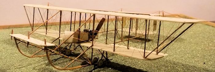 fore-aft wires
and rear strut wires on the fuselage for the same reason. Rig the tail struts
now because they too are easily accessible. Add the two struts at the ends of
the booms and rig these. Next are the front struts opposite the booms - these
should be rigged fore-aft now too, followed by all four boom struts which need
to be cut to the exact length and held in place with superglue. Do not rig the
boom struts yet. Rigging the struts at this stage was necessary because later
things become very crowded: it may sound risky with a weak structure but
actually provided your strut holes are correctly located the model should be
rigid enough to take careful handling and allow these operations top proceed
without damage. Finally add the last pairs of wing struts and the overhang
struts for the top wing and rig the rear and fore-aft wires. Set this assembly
aside for the time being.
fore-aft wires
and rear strut wires on the fuselage for the same reason. Rig the tail struts
now because they too are easily accessible. Add the two struts at the ends of
the booms and rig these. Next are the front struts opposite the booms - these
should be rigged fore-aft now too, followed by all four boom struts which need
to be cut to the exact length and held in place with superglue. Do not rig the
boom struts yet. Rigging the struts at this stage was necessary because later
things become very crowded: it may sound risky with a weak structure but
actually provided your strut holes are correctly located the model should be
rigid enough to take careful handling and allow these operations top proceed
without damage. Finally add the last pairs of wing struts and the overhang
struts for the top wing and rig the rear and fore-aft wires. Set this assembly
aside for the time being.
It is now time to
start making the undercarriage and front booms. The booms were made from 30 x 60
thou Evergreen strip. Bend one end gently to get most of the curve and then
trace the curve on to a block of wood. Pin the strip on to the drawing of the
curve and plunge the plastic into boiling water for about 10 seconds. They
should have the correct curve fixed. Bend the small curve at the rear using the
plan to get the correct location and length. Drill small holes where the struts
will fit later. Cut the undercarriage and boom struts from Evergreen strip and
shape to aerofoil section or use pre-shaped strut material. The undercarriage
struts were cut to the exact length but the boom supports were slightly longer
and will be trimmed to fit later. The undercarriage struts were then painted,
not forgetting the blue bands. Now take the main assembly and invert it. Glue
the vertical undercarriage struts into the holes under the wing and glue one of
the booms on to the ends. While this is still flexible glue the side struts into
place. You need to work quickly in order that the assembly stays properly
aligned. Leave this to dry out, supporting it if necessary. Repeat this
operation on the other side. Cut and fit the long support struts first as all of
these must be measured from the model to fit. Then add the shorter supports,
making sure to cut the ends at the correct angle to make a good joint with the
main supports. I glue everything with plastic cement and th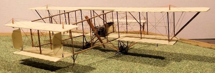 en re-enforce with
liquid cement. When this assembly is dry the painting can be finished. The axles
were cut from wire from a paper clip and the brackets holding the axles were
from thin rod - again refer to the excellent photos for details. I represented
the bungee springs with black thread.
en re-enforce with
liquid cement. When this assembly is dry the painting can be finished. The axles
were cut from wire from a paper clip and the brackets holding the axles were
from thin rod - again refer to the excellent photos for details. I represented
the bungee springs with black thread.
The wheels were
made by scribing 4 circles on to 60 thou card and then cutting out squares with
the circles in them. Reduce the squares to circles by cutting off the corners
with a knife or saw and then finishing with a file. Drill a hole in the centre
of the disc and then file the edges all around to get the taper of the wheel
covers. Strictly the wheels should be bare spokes but in this scale I gave up on
that idea and had covered wheels instead. The tyres were made by taking length
of 50 thou diameter rod and the handle of a metal round file. Bend the end of
the rod 90 degrees to give a small piece to hold on to with a pair of rat-nose
pliers. Hold the end of the plastic rod against the handle of the file, plunge
the handle of the file into boiling water and slowly rotate the file while
holding the plastic rod so that it is forced against the handle in the water. By
steadily rotating the handle the rod will form a spiral around the handle. When
you have 5 or 6 complete turns of plastic around the handle withdraw the handle
from the water but keep pulling the rod at both ends until it is cold. Slide the
rod off the handle and you will have a spring shaped coil. This can now be used
to cut the tyres - make sure that the diameter of the coil is less than that of
the discs so that the rod will fix hard on to the discs: if the coil diameter is
larger this method will not work. Place the rod ring over the card disc and push
the ends of the ring until you can measure the length that you need and cut it.
You will have to adjust the ends of the rod with a little careful bending and a
little filling may be necessary to get a good wheel. Use liquid cement to fix
the tyre to the disc. Any diameter wheel can be made this way - just adjust the
thickness of
 the rod to the size of the tyre required, and the diameter of the
spiral to the diameter of the wheel. Paint the wheels and fix to the axles with
superglue.
the rod to the size of the tyre required, and the diameter of the
spiral to the diameter of the wheel. Paint the wheels and fix to the axles with
superglue.
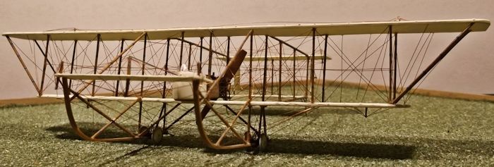
The tail skids and support struts were made from thin rod. The control horns were cut and shaped from Evergreen strip and hinges made for the rudders from rod inserted into tiny holes drilled in the edges. The rigging now has to be completed: do this systematically in order to avoid damage to work already done. Finish the fronts of the wings first, then the rear booms, tail unit and rudders (which should be rigged and fitted now), followed by the tail elevators, wing control surfaces and joining wires. Finally glue the front elevator on to the front booms and rig the bracing. Last rig the anti-drag wires on the rear booms, and finish by rigging the front booms and anti drag wires and balance wire on the top wing. Glue the propellor, windscreen, and control rod to the front elevator and you will have finished your model.
| CONCLUSIONS |
This is definitely not a project for a beginner - I have made several pushers conversions and complex biplanes - so I have some experience to draw upon. However it is nice to have a unique model in my collection and an aeroplane which is under represented in many other collections. It was also a long term project - it took about two months to build and there were the inevitable frustrations on the way, but it was worth it. In fact my biggest problem at the end was to find something else that could offer a similar challenge.
November 2015
Copyright ModelingMadness.com
If you would like your product reviewed fairly and fairly quickly, please contact the editor or see other details in the Note to Contributors.