1/72 Caudron G.IV
|
KIT #: |
|
|
PRICE: |
|
|
DECALS: |
Pegasus sheet of WW1 RFC/RNAS serials |
|
REVIEWER: |
Stephen Foster |
|
NOTES: |
Made from plastic sheet, rod and strut, an engine from Small
Stuff, and figures from W D Model |
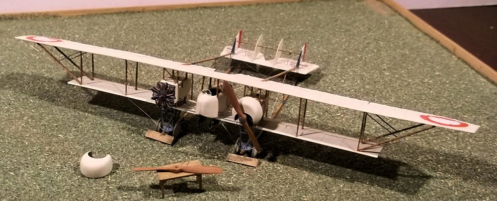
Rene and Gaston Caudron were brothers who were inspired by the
efforts of the Wright brothers in America, and who established a company to
build aircraft of their own designs in France. After a number of attempts to
come to a satisfactory design configuration, they developed the type G in
1913, which was improved to become the type G 3 in 1914. This was a two seat
machine with unequal span wings, twin booms holding the horizontal tail
surfaces and an 80hp rotary engine. This design was adopted by the French
military because it was available in quantity, but it had many limitations,
not the least of which was the inadequate view for the crew. The Aviation
Militaire called for a more powerful machine which could carry a forward
firing machine gun, so the Caudron brothers redesigned the basic G3 by
adding a second engine, placing a nacelle between the engines with the
observer in the front, and adding two extra fins and rudders to the tail:
otherwise the new machine was basically the same. The engines were 80hp Le
Rhone or Clerget rotaries and lateral control was by wing warping. 1800
machines would eventually be built in France and 12 were built in Britain as
part of a larger order for the RNAS. Caudrons served with French, British,
Italian and Russian air arms, and many continued in civilian service in the
early post war years. These machines were called Gitterrumpf (lattice tail)
by the Germans because of their distinct shapes, but t heir
frail appearance belied their strength: it was able to withstand
considerable damage and still return to the airfield with the crew. If the
Caudron GIV was flown aggressively it could prove to be a dangerous
adversary as shown by a number of successful engagements between French
crews and their opponents as they succeeded in downing many enemy machines
and several French air aces started their flying careers in Caudrons. It was
most widely employed in the unglamorous but important role of
reconnaissance, and as a bomber: in RNAS service it was mainly used as a
bomber.
heir
frail appearance belied their strength: it was able to withstand
considerable damage and still return to the airfield with the crew. If the
Caudron GIV was flown aggressively it could prove to be a dangerous
adversary as shown by a number of successful engagements between French
crews and their opponents as they succeeded in downing many enemy machines
and several French air aces started their flying careers in Caudrons. It was
most widely employed in the unglamorous but important role of
reconnaissance, and as a bomber: in RNAS service it was mainly used as a
bomber.
Although the Caudron GIII and GIV were both produced and used in large
numbers they have been almost forgotten and ignored until relatively
recently, which is one reason why this makes it an interesting subject to
model. The complexity of construction does not help improve its popularity
as a subject for a mass market model but it makes it an interesting
challenge for the scratch builder.
I decided to attempt this on a whim: I had bought the Windsock
DataFiles for the Caudron G III and GIV and thought that the latter offered
the bigger challenge: besides there is no kit of the G IV. This model was
made from plastic card, strip and rod, clear acetate, wire and wood. I did
cheat a little because I bought a resin engine from Small Stuff as I could
not scratch build one to that standard. The engine under the cowling was
scratch built however, but as it is largely concealed it is less important.
 Scratch building means that the order in which different components are made
is not very important, so I will describe the construction of the major
elements first, and then the order of assembly which is much more important,
later. I started with the cowlings which were push moulded from 40 thou
card, and the nacelle which was moulded from 30 thou card. The cowling mould
was the end of an old chair strut as it happened to be almost the exact
diameter that I required. The openings at the bottom were cut with a sharp
knife and finished with glass paper wrapped around the end of a paintbrush.
The fuselage nacelle was moulded so that the sides were deeper than the end
product which meant that I could cut the halves to the exact size later. The
rear underside was made from 10 thou card and the nose underside from clear
acetate as there was a window in the floor in front of the observer. The
cockpit openings were cut out from each side, making sure that they matched
exactly. The cabane struts were cut from 20 x 30 thou Evergreen strip which
was filed to aerofoil shape at one end. I then laid the fuselage halves on
to the plan to mark on where the struts were to be inserted and drilled the
holes for the struts from underneath in the cockpit sides before inserting
and glueing them in place. These formed part of the fuselage structure so
they must be added before any other details were put in. The interior detail
of the cockpits was based on photos in the DataFile: the observer's seat was
made from card and a floor put in beneath it, with the pilot's cockpit
having a seat, control column and push rods on the sides of the nacelle for
the engine controls. There do not seem to have been any instrument dials in
the cockpit so a simple bulkhead of 20 thou card was all that was needed.
The pilot's seat filled the whole of the rear of the nacelle and I simulated
this with a piece of 40 thou card bent to shape. Fitting the interior detail
was a little tricky, but when it was ready the two fuselage halves were
joined and the undersides added as previously described. A small hole was
also drilled in the top of the nacelle in front of the pilot's cockpit and a
small circular window inserted: this was made from clear acetate from a
blister pack.
Scratch building means that the order in which different components are made
is not very important, so I will describe the construction of the major
elements first, and then the order of assembly which is much more important,
later. I started with the cowlings which were push moulded from 40 thou
card, and the nacelle which was moulded from 30 thou card. The cowling mould
was the end of an old chair strut as it happened to be almost the exact
diameter that I required. The openings at the bottom were cut with a sharp
knife and finished with glass paper wrapped around the end of a paintbrush.
The fuselage nacelle was moulded so that the sides were deeper than the end
product which meant that I could cut the halves to the exact size later. The
rear underside was made from 10 thou card and the nose underside from clear
acetate as there was a window in the floor in front of the observer. The
cockpit openings were cut out from each side, making sure that they matched
exactly. The cabane struts were cut from 20 x 30 thou Evergreen strip which
was filed to aerofoil shape at one end. I then laid the fuselage halves on
to the plan to mark on where the struts were to be inserted and drilled the
holes for the struts from underneath in the cockpit sides before inserting
and glueing them in place. These formed part of the fuselage structure so
they must be added before any other details were put in. The interior detail
of the cockpits was based on photos in the DataFile: the observer's seat was
made from card and a floor put in beneath it, with the pilot's cockpit
having a seat, control column and push rods on the sides of the nacelle for
the engine controls. There do not seem to have been any instrument dials in
the cockpit so a simple bulkhead of 20 thou card was all that was needed.
The pilot's seat filled the whole of the rear of the nacelle and I simulated
this with a piece of 40 thou card bent to shape. Fitting the interior detail
was a little tricky, but when it was ready the two fuselage halves were
joined and the undersides added as previously described. A small hole was
also drilled in the top of the nacelle in front of the pilot's cockpit and a
small circular window inserted: this was made from clear acetate from a
blister pack.
 The
nacelles were made from a square of 60 thou card for the front with the
sides from 20 thou card, and the top and bottom from 30 thou card. I cut the
struts from 20 x 30 thou Evergreen strip which had been filed to a
streamline shape, and made them a little longer than necessary so that they
could be trimmed to the exact size later. I glued the top and bottom of the
nacelles to the front plates and laid these on to the plans so that I could
mark the correct places for the struts. Small recesses were cut into the top
and bottom plates before the struts were cemented to them. I checked that
the nacelle struts lined up with the struts in the fuselage as all of these
have to be of the same spacing if the model is not to look odd. When I was
happy with the strut positions I cemented the nacelle sides on. There was an
instrument dial on the insides of the nacelles and a fuel gauge: the former
was shaped from small pieces of 20 thou card and the latter from stretched
sprue. I drilled a hole on the inside of the nacelles where the control rods
would later be fixed and the pipe under the nacelle was made from rod. On
top of the nacelles were two filler caps, also made from small pieces of
rod.
The
nacelles were made from a square of 60 thou card for the front with the
sides from 20 thou card, and the top and bottom from 30 thou card. I cut the
struts from 20 x 30 thou Evergreen strip which had been filed to a
streamline shape, and made them a little longer than necessary so that they
could be trimmed to the exact size later. I glued the top and bottom of the
nacelles to the front plates and laid these on to the plans so that I could
mark the correct places for the struts. Small recesses were cut into the top
and bottom plates before the struts were cemented to them. I checked that
the nacelle struts lined up with the struts in the fuselage as all of these
have to be of the same spacing if the model is not to look odd. When I was
happy with the strut positions I cemented the nacelle sides on. There was an
instrument dial on the insides of the nacelles and a fuel gauge: the former
was shaped from small pieces of 20 thou card and the latter from stretched
sprue. I drilled a hole on the inside of the nacelles where the control rods
would later be fixed and the pipe under the nacelle was made from rod. On
top of the nacelles were two filler caps, also made from small pieces of
rod.
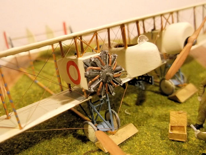
I made one engine from scrap using a disc of 60 thou and 20 thou card
laminated and shaped to form the circular block, and 80 thou rod for the
cylinders.The cylinders were scored to simulate the cooling fins, and then
pieces of stretched sprue were used for the spark plugs. I added the valve
gear on the ends of the engines to two cylinders as only these would be
seen. The push rods were thin stretched sprue and the copper inlet pipes
were from thin card. Only five sets of spark plugs, rods and inlet pipes
were made as the remainder of the engine is concealed beneath the cowling. I
used the Small Stuff engine as a model to work from. I put a pin of plastic
rod in to the rear of the engine and drilled a hole into the front of one
nacelle so that I could mount the engine later. The Small Stuff engine is a
wonderful model in its own right and has the crankshaft of exactly the right
diameter and length moulded on it so it can be easily glued to the front of
the nacelle at a later date. I painted both engines at this stage as they
were easy to handle. I used black with a little silver for the crank case
and cylinders, copper with a little grey for the intake pipes and silver for
the push rods. The propellors were carved from wood - I have some thin
hardwood strip which I used for my model. Holes were drilled in the centre
to hold a pin for one and represent where the drive shaft would go for the
other. The propellor bosses were discs cut from 10 thou card.
 The
wings were made by cutting a strip of 20 thou card and a wider strip of 10
thou card and gluing them together and holding them in a press while they
dried. I then cut a strip of 20 thou card and bevelled it to a triangular
cross section to form the trailing edge of the upper wing section. The ribs
of the forward part of the upper wing were cut from 10 x 20 thou Evergreen
strip held by liquid glue. Similarly the ribs on the underside of the wing
were made from the same material. The ribs on the trailing edge of the upper
wing were glued into place and then the bevelled card was cut into sections
and inserted between the ribs. Any gaps need to be filled with filler and
then the ribs were rubbed down to the required thickness both above and
below the wings. This was a long and tedious process and required a good
deal of patience, but was important as the complex shape of the wings had to
be reproduced. Finally the trailing edges of the wings were scalloped using
a round file and the tips shaped, using the plans as a guide. On the lower
wing the metal plates beneath the nacelles were made from 10 thou card which
was glued on with liquid cement and then rubbed down to a thin section.
Holes were drilled in top of the lower wing for the various struts, and on
the underside for the undercarriage legs. I used the engine nacelle struts
as a guide for the distances between the front and rear holes and then laid
the wings against the plans to get the correct position for the outer
struts. The fuselage struts were used to position the holes for the cabanes.
The
wings were made by cutting a strip of 20 thou card and a wider strip of 10
thou card and gluing them together and holding them in a press while they
dried. I then cut a strip of 20 thou card and bevelled it to a triangular
cross section to form the trailing edge of the upper wing section. The ribs
of the forward part of the upper wing were cut from 10 x 20 thou Evergreen
strip held by liquid glue. Similarly the ribs on the underside of the wing
were made from the same material. The ribs on the trailing edge of the upper
wing were glued into place and then the bevelled card was cut into sections
and inserted between the ribs. Any gaps need to be filled with filler and
then the ribs were rubbed down to the required thickness both above and
below the wings. This was a long and tedious process and required a good
deal of patience, but was important as the complex shape of the wings had to
be reproduced. Finally the trailing edges of the wings were scalloped using
a round file and the tips shaped, using the plans as a guide. On the lower
wing the metal plates beneath the nacelles were made from 10 thou card which
was glued on with liquid cement and then rubbed down to a thin section.
Holes were drilled in top of the lower wing for the various struts, and on
the underside for the undercarriage legs. I used the engine nacelle struts
as a guide for the distances between the front and rear holes and then laid
the wings against the plans to get the correct position for the outer
struts. The fuselage struts were used to position the holes for the cabanes.
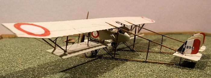
The tail surfaces were cut from 20 thou card using a tracing from the
plans: as with the wings the shapes of the fins and rudders varied on
different machines. My model represents a French built RNAS machine, but
other aircraft had different shaped rudders and wings. All of the struts
were shaped from 20
 x 30 thou
Evergreen strip. The wheels were made by shaping 4 discs of 60 thou card and
the tyres by coiling a length of 40 thou rod around the handle of a file and
putting it in boiling water for 10 seconds. The coil of plastic rod was then
cut to length and the ends twisted until they lined up. I placed the rod
over the discs of card and glued with liquid cement. The axles were cut from
wire as were the undercarriage legs. The booms were from 40 x 30 thou
Evergreen strip and were made by bending the strip to the correct curve of
the front of the boom. The strip was then laid on a plan and the strut
locations marked so the holes could be drilled in the correct places. When
the holes had been drilled I held the booms on the plan with pins and glued
the struts into place.
x 30 thou
Evergreen strip. The wheels were made by shaping 4 discs of 60 thou card and
the tyres by coiling a length of 40 thou rod around the handle of a file and
putting it in boiling water for 10 seconds. The coil of plastic rod was then
cut to length and the ends twisted until they lined up. I placed the rod
over the discs of card and glued with liquid cement. The axles were cut from
wire as were the undercarriage legs. The booms were from 40 x 30 thou
Evergreen strip and were made by bending the strip to the correct curve of
the front of the boom. The strip was then laid on a plan and the strut
locations marked so the holes could be drilled in the correct places. When
the holes had been drilled I held the booms on the plan with pins and glued
the struts into place.
With all of the sub-assemblies complete the main assembly could begin. I
started by gluing the fuselage nacelle to the lower wing and then painted
the wings, fuselage nacelle, engine nacelles, tail surfaces and struts as
all of these will be difficult to paint later. I used Humbrol enables and
mixed the clear doped linen from an old tin of Clear Doped Linen and white.
The markings were hand painted except the serial which came from a Pegasus
sheet of WW1 RFC/RNAS serials.
I then attached the engine nacelles to the lower wing: first one side
which was allowed to dry, and then the other. Alignments of struts had to be
carefully checked, as did the level of the nacelles fore-aft and side to
side. I had cut the struts to be slightly too long so that I could trim them
as required. The wires under the sides and rear of the nacelles, and struts
under the front were added at this stage, as were the control rods between
the fuselage and engine nacelles. The strut location holes for the cabanes
and engine nacelles under the top wing were measured by placing the top wing
upside down and placing the
 lower
wing assembly on to it. Then the strut positions could be marked and
drilled. The outer wing strut locations were marked from the holes in the
lower wing. Glue was dropped into the holes in the top wing for the engine
nacelle and cabane struts and the top wing placed on the lower wing
assembly, carefully aligned and supported, and allowed to dry out. When the
assembly was dry I added the outer wing struts and rigged the top of the
nacelles and cabanes. The inner wing struts were added next and the rear
struts rigged, as were the fore aft wires between the struts. The struts
supporting the wing overhangs and the bracing were added last.
lower
wing assembly on to it. Then the strut positions could be marked and
drilled. The outer wing strut locations were marked from the holes in the
lower wing. Glue was dropped into the holes in the top wing for the engine
nacelle and cabane struts and the top wing placed on the lower wing
assembly, carefully aligned and supported, and allowed to dry out. When the
assembly was dry I added the outer wing struts and rigged the top of the
nacelles and cabanes. The inner wing struts were added next and the rear
struts rigged, as were the fore aft wires between the struts. The struts
supporting the wing overhangs and the bracing were added last.
The front ends of the booms were chamfered slightly so that the leading
edges were almost flat against the top wing - the front tapered in line with
the wing surface. The wing sub-assembly was placed over a copy of the plans
and the booms placed so that their leading edges were on the top wing. The
model was mounted on a small block during this operation to give the
necessary clearance under the lower wing. The booms were glued into place
and held with clips while they dried. The undercarriage legs were cut from
the wire from a length of telephone extension cable which had been rolled
flat on a block of wood, and held in place with CA. When the undercarriage
was complete I glued the horizontal tail surface to the rear of the booms,
having first drilled holes where the rear posts would go. As I glued the
tail unit to the booms I added the vertical struts, also from wire and held
in place with CA - this reinforced the rear and held it in
 place.
Care was needed with alignments at all stages of the boom assembly because
even small errors would show up on the finished model. The fins and rudders
were added after the horizontal surface was dry. The axles were added to the
front of the booms followed by the axle covers which had been cut and shaped
from an aluminium drink can.
place.
Care was needed with alignments at all stages of the boom assembly because
even small errors would show up on the finished model. The fins and rudders
were added after the horizontal surface was dry. The axles were added to the
front of the booms followed by the axle covers which had been cut and shaped
from an aluminium drink can.
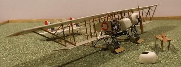
The remaining rigging of the model was fairly straightforward. I
finished the wings and rigged part of the tail before adding the control
column in the pilot's cockpit, also from wire, and the pilots windscreen,
bomb racks from scrap thin strip, release levers and cables (wire). Only
then did I attempt the control cables to the elevator and rudder, and the
undercarriage. The wheels were finally put on to the axles and the sit of
the model checked - some very small adjustments were necessary to get the
booms to rest properly. The model could now stand upright while the engines
were glued to the front of the nacelles and one of the cowlings placed over
the scratch built engine. A windscreen for the observer and brackets for the
cowling on the nacelle without a cowling, plus the propeller, completed the
model. Figures from WD Models were added to the base to give more interest.
Copper State Models make a resin kit of this aircraft in 1/48
scale, but for some reason nobody makes one in the Gentlemens’ Scale so I
had no option but to scratch build my own. This was one of the more complex
projects that I have attempted, the bigger problems being aligning the
struts for the engine and fuselage nacelles and the booms at the rear. Once
these issues had been resolved the model was no more difficult than
assembling any other kit, except that I had to make most of the parts first.
The Small Stuff engine meant that I could leave one engine exposed,
otherwise I would have had to cover both with cowlings. This fills another
gap in my collection of early military aircraft that served in considerable
numbers.
Windsock DataFile No 96: The Caudron
G IV. J Guttman, 2002.
Stephen Foster5 November 2018
Copyright ModelingMadness.com
If you would like your product reviewed fairly and fairly quickly, please contact the editor or see other details in the
Note to
Contributors.
Back to the Main Page
Back to the Review
Index Page
Back to the Previews Index Page