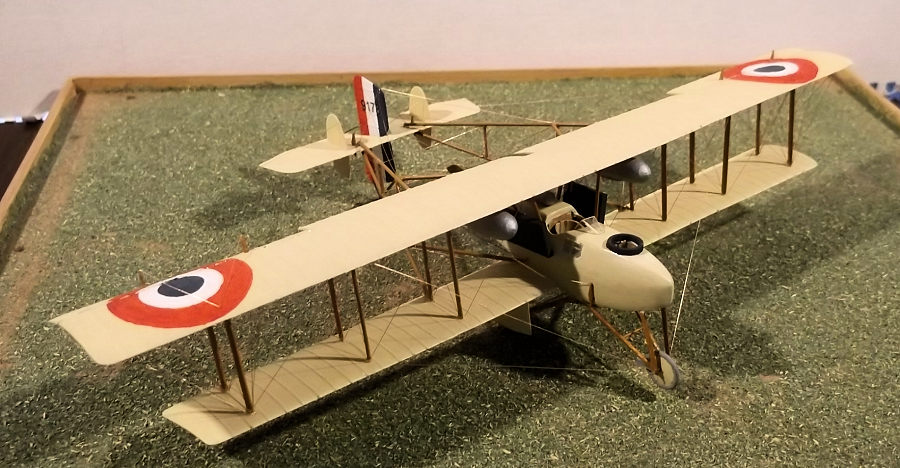
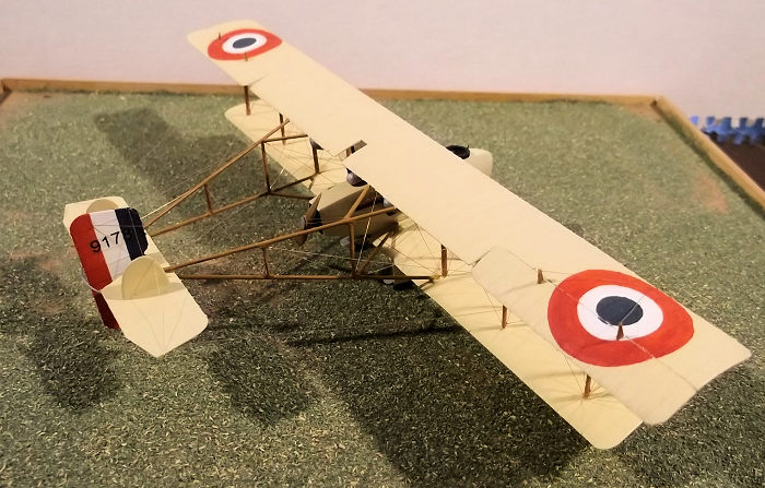
1/72 Breguet Br(M)4
In August 1914 the Michelin brothers (who owned and ran the Michelin
tyre company), offered to buy and donate 100 bombers to the French air
force. The type chosen was a Breuget design: a pusher powered by a 200hp
Canton-Unne engine, but only 47 machines had been delivered by November 1915
and 75 by January 1916. One of the problems which caused the delays in
delivery was manufacturing the engines. Another problem that the ground
crews had to overcome was maintaining the machines in service. Pilots found
the type difficult to handle and accidents and therefore damage to machines
was common.
 The slow introduction into service meant that the type was almost obsolete
by the time sufficient numbers were available for the purposes for which
they were designed, i.e. day bombing, as by then they were too slow and
poorly armed. In addition to the bomber variants (the Br (M) 4 had special
bomb holders under the wing designed by the Michelin company), the Br 5 was
built which was supposed to be a fighter: it was armed with two machine
guns, one of which fired rearwards over the top wing. These too were of
limited practical use as they were also too slow and not nearly manoeuvrable
enough for service on the Western Front. Consequently the bombers were
transferred to night operations in October 1916 in which role it continued
until January 1918. The RNAS purchased 25 machines from France, and another
30 which were powered by 250hp Rolls Royce engines built by Graham-White
Aviation, but only 10 of this order were completed. The RNAS machines
operated with No 3 wing in France and some also operated in the Agean area,
but they were not popular with their crews and saw limited service.
The slow introduction into service meant that the type was almost obsolete
by the time sufficient numbers were available for the purposes for which
they were designed, i.e. day bombing, as by then they were too slow and
poorly armed. In addition to the bomber variants (the Br (M) 4 had special
bomb holders under the wing designed by the Michelin company), the Br 5 was
built which was supposed to be a fighter: it was armed with two machine
guns, one of which fired rearwards over the top wing. These too were of
limited practical use as they were also too slow and not nearly manoeuvrable
enough for service on the Western Front. Consequently the bombers were
transferred to night operations in October 1916 in which role it continued
until January 1918. The RNAS purchased 25 machines from France, and another
30 which were powered by 250hp Rolls Royce engines built by Graham-White
Aviation, but only 10 of this order were completed. The RNAS machines
operated with No 3 wing in France and some also operated in the Agean area,
but they were not popular with their crews and saw limited service.
I am not aware that any kit has been made of this type in any medium in this
scale, but if anyone knows otherwise I would be pleased to hear from them.
So if a modeller wants this aircraft in their collection they have only one
option, to scratch build one.
 I started as I usually do with my scratch builds by cutting out the flying
surfaces from 30 thou plastic card. In order to get the curvature I took a
sheet of card and put it into a piece of drain pipe which had been sealed at
one end: very hot water was poured into the pipe and drained off after about
10 seconds. This gave me a suitable piece of plastic from which I have been
able to cut many wings and other flying surfaces for other models. The ribs
were added by adding 10 x 20 thou Evergreen strip which was attached to the
upper surfaces with liquid cement. When the cement had set overnight I
sanded the edges of the strip down and then sealed them with primer. The
ailerons and elevators were cut out so that they could be re-attached later
at a slight angle.
I started as I usually do with my scratch builds by cutting out the flying
surfaces from 30 thou plastic card. In order to get the curvature I took a
sheet of card and put it into a piece of drain pipe which had been sealed at
one end: very hot water was poured into the pipe and drained off after about
10 seconds. This gave me a suitable piece of plastic from which I have been
able to cut many wings and other flying surfaces for other models. The ribs
were added by adding 10 x 20 thou Evergreen strip which was attached to the
upper surfaces with liquid cement. When the cement had set overnight I
sanded the edges of the strip down and then sealed them with primer. The
ailerons and elevators were cut out so that they could be re-attached later
at a slight angle.
The nacelle was push moulded from 30 thou card and the window
openings cut out before I detailed the interior with 10 x 20 thou strip. The
cockpit floors and instruments were made up from thin card and rod, but as
very little can be seen I did not spend too much time in this area. The
windows were made from thin acetate sheet from the packaging of an old
Airfix kit. The engine was entirely enclosed in the rear of the nacelle so I
only had to add strips of thick card on the inside where the exhausts would
be attached later. The oil tank was
 shaped from a thick piece of sprue: the
fuel tanks were from bombs from an old kit which I made when I was a
teenager so I have no idea which one they came from. The radiators and bomb
containers were made from 60 thou card which had been laminated to give the
correct thickness. I scribed the gun ring from 20 thou card using a pair of
dividers to score the plastic.
shaped from a thick piece of sprue: the
fuel tanks were from bombs from an old kit which I made when I was a
teenager so I have no idea which one they came from. The radiators and bomb
containers were made from 60 thou card which had been laminated to give the
correct thickness. I scribed the gun ring from 20 thou card using a pair of
dividers to score the plastic.
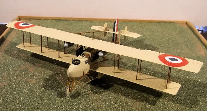
Having made up the nacelle the lower wings were glued to the sides
and the assembly was allowed to set before I attached the booms. These were
from florists wire which had the advantage of being cheap and easy to cut
but robust enough to support the weight of the tail unit without bending.
They were attached to both wings using 2 part epoxy. Finally I cemented the
bomb containers to the lower wings.
 Readers who have followed my previous descriptions of building
biplanes will know that I paint them at this stage, before I add the upper
wing as this means that all parts of the model can be accessed easily. I
used a mixture of Humbrol white and cream (103) for the nacelle and flying
surfaces. The national markings on the wings were hand painted: I scribe the
outer circle with a pair of dividers and paint three thin coats of white
inside it. Then I scribe the inner circle for the blue ring and a circle for
the red and paint these. Provided that care is taken the paint will run to
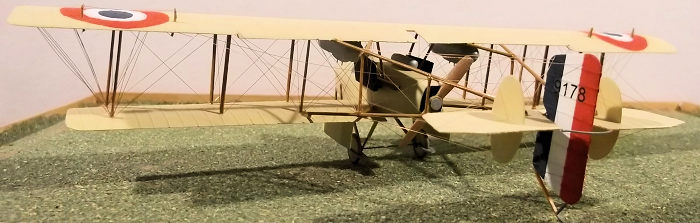
the groove of the circle and give a sharp edge. The numerals on the rudder
were from an old set of transfers in my spares box. The struts were Revell
semi-matt tan (332) . The tyres were dark grey. My model is based on an
aircraft flown by 3 Wing of the Royal Navy Air Service at Dunkirk in late
1915.
Readers who have followed my previous descriptions of building
biplanes will know that I paint them at this stage, before I add the upper
wing as this means that all parts of the model can be accessed easily. I
used a mixture of Humbrol white and cream (103) for the nacelle and flying
surfaces. The national markings on the wings were hand painted: I scribe the
outer circle with a pair of dividers and paint three thin coats of white
inside it. Then I scribe the inner circle for the blue ring and a circle for
the red and paint these. Provided that care is taken the paint will run to
the groove of the circle and give a sharp edge. The numerals on the rudder
were from an old set of transfers in my spares box. The struts were Revell
semi-matt tan (332) . The tyres were dark grey. My model is based on an
aircraft flown by 3 Wing of the Royal Navy Air Service at Dunkirk in late
1915.
With all the main components painted I added oil tank and exhausts, the
latter were 80 thou rod with 20 thou rod to attach them to the nacelle
sides. Now I could put on the top wing. I did this as I normally do with
wings which have multiple struts: I cemented the inner pairs of struts to
the lower wing and then gently lowered the upper wing on to the struts.
Prior to lowering the wing I placed small drops of glue into the locating
holes in the underside top the top wing so that glue does not get smeared
over the paint. The assembly must be placed over a plan to ensure the
correct alignment of wings and booms and jigged while the glue sets for at
least two hours. Now the horizontal tail surface, complete with vertical stabilisers can be slipped between the tail ends of the booms and fixed with
C A. The rest of the wing struts were carefully inserted a pair at a time on
alternate sides, starting nearest the nacelle, followed by the vertical boom
struts. Finally the cabane struts were put into place followed by the
radiators. The fuel tanks under the top w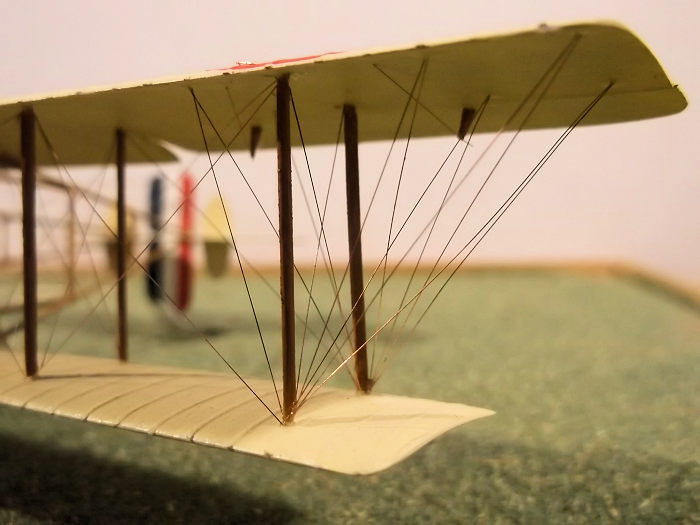 ing completed this part of the
structure. The undercarriage was next - the struts inserted into slots which
had been made on the underside of the nacelle. The axle was from thin wire
on this model for additional strength. The wheels were made from discs of
card with rod tyres. The rudder was glued to the horizontal stabilizer and
the wire curve C A’d to the elevators. I carved the propellor from a strip
of hardwood.
ing completed this part of the
structure. The undercarriage was next - the struts inserted into slots which
had been made on the underside of the nacelle. The axle was from thin wire
on this model for additional strength. The wheels were made from discs of
card with rod tyres. The rudder was glued to the horizontal stabilizer and
the wire curve C A’d to the elevators. I carved the propellor from a strip
of hardwood.
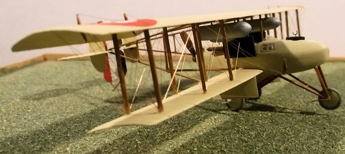
I rig my pusher models with 40 SWG rolled copper wire held with C A.
This does take time but is worth the effort. Sections are measured using a
pair of dividers and the pieces of wire checked for length before I add any
glue. The glue is applied with the tip of an old scalpel blade to the
attachment points. I always start with the cabane and inner wings and work
systematically outwards from the least accessible wires: the long control
wires to the tail and those from the control horns to ailerons, elevators
and rudder are the last to be fixed. Note that Br 4 and 5 types sat on their
tail when they were empty, but on the nose wheel when they were loaded so it
does not matter if your model turns into a tail sitter: just tell people
that it is unloaded! Of course if you want the model to sit on its nose then
a small weight will have to be added to the nose during construction of the
nacelle.
Pusher aircraft are not the most popular models to construct, but they
always attract attention from others. They formed an important part of the
air component of the Allied forces in the first three years of WW1 so if a
modeller wishes to have a representative collection of types used in WW1 by
the RFC and French air service, some pushers must feature. This was not a
type that I would recommend to someone who is building their first pusher as
the boom assembly is rather awkward on this type, but once the dark arts of
pusher model assembly have been mastered, it would present few problems.
Breuget Br 4 and Br 5 types were not an important element of the air
services, but they are interesting examples of the pusher layout.
Stephen Foster
24 September 2019
Copyright ModelingMadness.com
If you would like your product reviewed fairly and fairly quickly, please
contact
the editor or see other details in the
Note to
Contributors.
Back to the Main Page
Back to the Review
Index Page
Back to the Previews Index Page