| KIT #: | |
| PRICE: | |
| DECALS: | Yes |
| REVIEWER: | Stephen Foster |
| NOTES: | Scratch built |
| HISTORY |
 The Hansa-Brandenburg W. 13 was designed by Ernst Heinkel and his team for the
German Navy but they showed no interest in it so it was offered instead to the
Austro-Hungarian Navy KuK Kriegsmarine) who had issued a specification for a
large general purpose flying boat powered by a 350 hp Austro-Daimler engine. The
navy ordered 60 machines in late 1916, the first of which was delivered in March
1917. Following the crash of the first example, delivery was delayed such that
delivery of the the following 15 aircraft was not completed until March 1918. A
shortage of engines meant that although most of the airframes were delivered in
1917-1918, many of the 134 manufactured were placed in storage and not used
operationally.
The Hansa-Brandenburg W. 13 was designed by Ernst Heinkel and his team for the
German Navy but they showed no interest in it so it was offered instead to the
Austro-Hungarian Navy KuK Kriegsmarine) who had issued a specification for a
large general purpose flying boat powered by a 350 hp Austro-Daimler engine. The
navy ordered 60 machines in late 1916, the first of which was delivered in March
1917. Following the crash of the first example, delivery was delayed such that
delivery of the the following 15 aircraft was not completed until March 1918. A
shortage of engines meant that although most of the airframes were delivered in
1917-1918, many of the 134 manufactured were placed in storage and not used
operationally.
The first W. 13 to see action was K366 in August 1917 and this machine was used on subsequent bombing operations until it was shot down in October 1917. Other machines were used in the bombing and reconnaissance over the Adriatic Sea. Durazzo, (an Italian port), was bombed successfully in June 1918, and later in the closing months of the war they were deployed against land targets in Bulgaria.
One machine (K405) was taken by the Americans as war reparation in 1919 and shipped to the USA where it was stripped down and rebuilt. It was thoroughly tested before being scrapped in 1922.
| CONSTRUCTION |
I started by cutting out blanks for the wings from 30 thou
card which had been bent in a water pipe which had been sealed at one end and
boiling water poured in. The upper wing was swept back but had a straight
central section - this latter was cut separately. The horizontal tail surfaces
were cut from flat 30 thou card. All the surfaces were rounded at the front and
sanded to give thin trailing edges. A strip of 10 thou card was glued to the
leading edges of the top surfaces of the wings to
 represent
the reinforced leading edge, and then 10 x 20 thou Evergreen strip was glued and
sanded almost flat. Mr Surfacer filler was run over these strips and they were
again sanded to give slightly elevated rib effect. The upper wing sections were
butt joined with liquid cement. The ailerons were cut from the top wing and the
trailing edges scalloped using a round file and fine grade sand paper. Holes
were drilled in the wings ready to take struts and floats later. A fin was
shaped from 60 thou card.
represent
the reinforced leading edge, and then 10 x 20 thou Evergreen strip was glued and
sanded almost flat. Mr Surfacer filler was run over these strips and they were
again sanded to give slightly elevated rib effect. The upper wing sections were
butt joined with liquid cement. The ailerons were cut from the top wing and the
trailing edges scalloped using a round file and fine grade sand paper. Holes
were drilled in the wings ready to take struts and floats later. A fin was
shaped from 60 thou card.
The hull was made up by cutting the sides and rear top and bottom surfaces from 30 thou card and joining these to a series of card bulkheads. This gave a basic structure to which I could add the upper part of the front of the hull which was made by laminating sheets of thick card to obtain the desired depth. Holes were drilled and shaped for the cockpit opening and gunner’s cockpit. Basic details for both cockpits, consisting of a control column, instrument panel and seats were cemented to the floor piece of the lower part of the hull: as not much can be seen on the model I did not spend too much time on these details. The rear surface of the upper cockpit decking was smoothed with filler. The front part of the lower hull was stepped: this was achieved by cutting a piece of 80 thou card to fit the underside of the hull and bending it in hot water to fit the lower contour of the hull. This had a double curved underside: when the hull piece was secure I gently filed the curves with a round file and smoothed them with fine sand paper wrapped around a piece of dowel. The lower wings were butt joined to the fuselage and the fin glued to the rear top decking so that I could add the horizontal tail surfaces prior to painting the sub-assembly and top wing.
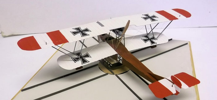
| COLORS & MARKINGS |
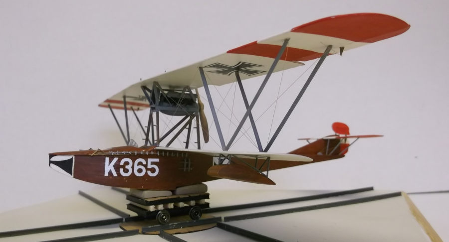
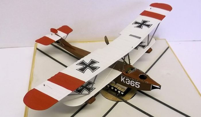
I always paint my biplane models after I have fixed the lower wing but before I attach the upper wing. On this model I did not attempt to mount the engine frame until the painting was done as this would also have interfered with the painting process. The fuselage was undercoated with Revell Ocre acrylic and then a mixture of burnt Sienna and raw Sienna oil paints were applied. When these were dry I could paint the wings: acrylic white with a very small amount of Humbrol 103 clear doped linen. The red stripes were also acrylics. The national markings and serial on the nose were custom printed by Arctic Decals. The nose cross was hand painted.
| FINAL CONSTRUCTION |
 The engine was scratch built from plastic sheet which was laminated and shaped
to make the sump, with plastic rod for the cylinders. Thin plastic rod was
shaped to make the fuel pipes, thick sheet for the valve covers and rod and
strip for other details. Again much of this will be hidden under the wing so
very small details were omitted.
The engine was scratch built from plastic sheet which was laminated and shaped
to make the sump, with plastic rod for the cylinders. Thin plastic rod was
shaped to make the fuel pipes, thick sheet for the valve covers and rod and
strip for other details. Again much of this will be hidden under the wing so
very small details were omitted.
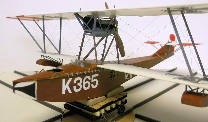
The engine frame and struts were shaped from 30 x 60 thou Evergreen plastic strip. The engine frame was fixed first, and the engine, which had been painted, set in place. I should have put the underwing floats on before I mounted the engine but I mounted the wing on paint pots while the floats were attached. They were made from 30 thou card with internal bulkheads and rod for struts.
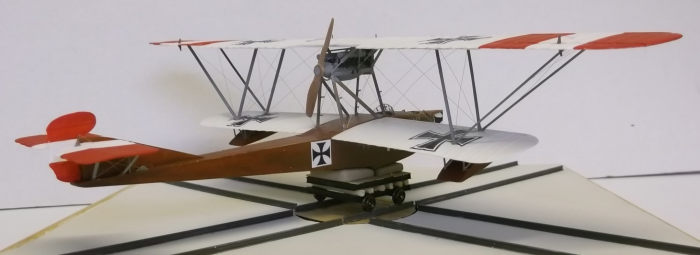
Mounting the top wing on biplanes presents problems
for many modellers, especially if the wings are staggered or, as in this case,
the struts form a V profile. To get over this problem I made a pair of supports
from cardboard - any source will do, including cereal packets of the stiffeners
from reals of file paper. I place one on each lower wing and lay the upper wing
on top. By carefully measuring the outer struts and cutting the m to fit these
can be cemented into place while the card
 supports
take the weight of the top wing. When the outer struts had set, and with the
card jigs still I place I fixed the adjacent set of struts which form a v
between the lower and upper wings. When these had set the card jigs could be
carefully removed and the top wing was secure enough for me to add the cabane
struts between the engine frame and top wing. Final details such as the radiator
in front of the engine, rudder, ailerons and control horns bomb racks on the
fuselage sides and propellor completed the assembly. The model was rigged with
40 SWG rolled copper wire held in place with CA.
supports
take the weight of the top wing. When the outer struts had set, and with the
card jigs still I place I fixed the adjacent set of struts which form a v
between the lower and upper wings. When these had set the card jigs could be
carefully removed and the top wing was secure enough for me to add the cabane
struts between the engine frame and top wing. Final details such as the radiator
in front of the engine, rudder, ailerons and control horns bomb racks on the
fuselage sides and propellor completed the assembly. The model was rigged with
40 SWG rolled copper wire held in place with CA.
I wanted to mount the model on a small trolley and railway system of the type used by the Austro-Hungarian flying boat stations. The trolley was cobbled together from plastic strip shape like a steel girder to make a frame, hardwood strip, obechi fro the wood sleepers, balsa for the pads and N gauge coach wheels from Bachmann, the latter were mounted on brass rod. The base was a piece of hardboard with a circle cut with a circle cutter and the rails were standard model railway stock. The top of the turntable was covered with hardwood strip and the base painted with acrylics, but I have yet to weather the surface.
| CONCLUSIONS |
There is no kit of this aircraft that I am aware of, so as I like the flying boats used by Austria-Hungary the only option I had was to scratch build one. I have experience of building flying boats including the H-B C C and Phoenix Type A, (both reviewed on this site), so to tacle a third was not too difficult for me. However the strut arrangement and engine platform would present challneges to a modeller new to scratch building, so I would not recommend this as a first project. For a modeller with some scratch building experience however this would be an interesting subject to tackle.
| REFERENCES |
The Hansa-Brandenburg W. 13 by George Haddow: Windsock DataFile Publication No 119, 2005.
There are various sources and photographs of this type on the internet, but it is not one of the better referenced aircraft.
Stephen Foster
22 March 2022
Copyright ModelingMadness.com. All rights reserved. No reproduction in part or in whole without express permission.
If you would like your product reviewed fairly and fairly quickly, please contact the editor or see other details in the Note to Contributors.