1/72 Hansa-Brandenberg CC
|
KIT #: |
Scratch built |
|
PRICE: |
$ |
|
DECALS: |
Letraset dry rub down, and home
printed |
|
REVIEWER: |
Stephen Foster |
|
NOTES: |
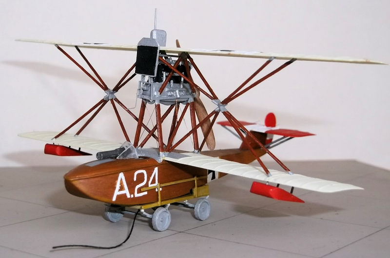
An unusual type which presented an interesting challenge which was
not as difficult as anticipated. |
The Hansa Brandenburg CC was named after Camillo Castiglione a banker
who bought the Hansa and Brandenburgisch Fleugzeug-Werke Gmbh in
1916. The machine was designed by Ernst Heinkel and was p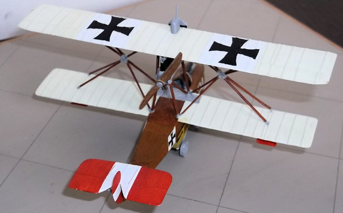 owered by a
Benz III 150 hp engine, a Heiro 220 hp engine or an Austro-Daimler 185
hp engine. It was used as a short range defensive fighter by the
Austro-Hungarian navy and there was hope that the German navy would use
them too but they accepted only one machine as German naval pilots
tended to prefer floatplanes. The unusual multiple V strut, (or star
strut), configuration had been used on the Hansa-Brandenburg D1 fighter
and the Hansa-Brandenburg KDW - a D1 on floats. 35 CC machines were
built by Phoenix: most were used by the Austro-Hungarian navy for
protection of harbours and bases on the Adriatic coast. Lt Gottfried
Banfield was the best known of the navy pilots to fly one of these
machines which were in service during the summer and autumn of 1917.
They were able to hold their own against the Italian flown Nieuport 11,
and although they were less manoeuvrable than the Nieuports they were
slightly faster. Early machines were fitted with one machine gun but
later examples had two.
owered by a
Benz III 150 hp engine, a Heiro 220 hp engine or an Austro-Daimler 185
hp engine. It was used as a short range defensive fighter by the
Austro-Hungarian navy and there was hope that the German navy would use
them too but they accepted only one machine as German naval pilots
tended to prefer floatplanes. The unusual multiple V strut, (or star
strut), configuration had been used on the Hansa-Brandenburg D1 fighter
and the Hansa-Brandenburg KDW - a D1 on floats. 35 CC machines were
built by Phoenix: most were used by the Austro-Hungarian navy for
protection of harbours and bases on the Adriatic coast. Lt Gottfried
Banfield was the best known of the navy pilots to fly one of these
machines which were in service during the summer and autumn of 1917.
They were able to hold their own against the Italian flown Nieuport 11,
and although they were less manoeuvrable than the Nieuports they were
slightly faster. Early machines were fitted with one machine gun but
later examples had two.
 There is at least one vacuform kit available in 1/72 scale but it is a
rare bird these days, and there is also a resin kit in 1/48 scale. I am
not a vacuform kit builder so I found some plans on the net and decided
to make one of my own. I knew that the star struts would be a challenge,
but as I do not like to build a model without one this was reason enough
for me to give it a try. I was also attracted by the colourful
Austro-Hungarian Navy markings which are brighter than those found on
many British types. I used the standard materials of any scratch builder
or converter of kits, namely plastic card, rod, and strip, wood for the
propellor and an m/g from Aeroclub.
There is at least one vacuform kit available in 1/72 scale but it is a
rare bird these days, and there is also a resin kit in 1/48 scale. I am
not a vacuform kit builder so I found some plans on the net and decided
to make one of my own. I knew that the star struts would be a challenge,
but as I do not like to build a model without one this was reason enough
for me to give it a try. I was also attracted by the colourful
Austro-Hungarian Navy markings which are brighter than those found on
many British types. I used the standard materials of any scratch builder
or converter of kits, namely plastic card, rod, and strip, wood for the
propellor and an m/g from Aeroclub.
I started with the hull which was made from 30 thou card, with two
pieces for the sides and a third for the hull bottom forward of the
step. The card was bent by pulling the card between edge of a scissors
blade and my fingers along the parts that I wanted to bend. I used 30
thou card formers to make a box structure to hold the sides and bottom
square. The cockpit details included a seat, control column, ru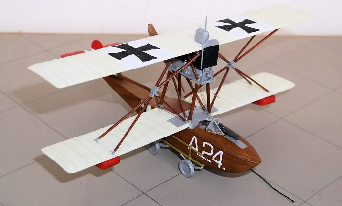 dder bar,
ammunition boxes etc and were put into the fuselage before I mounted the
top of the hull. The rear of the hull, top and bottom, were also card.
The forward deck was made by laminating two pieces of 40 thou card which
was sanded and filed to shape after it had been glued into place. The
cockpit opening was scribed with a pair of dividers.
dder bar,
ammunition boxes etc and were put into the fuselage before I mounted the
top of the hull. The rear of the hull, top and bottom, were also card.
The forward deck was made by laminating two pieces of 40 thou card which
was sanded and filed to shape after it had been glued into place. The
cockpit opening was scribed with a pair of dividers.
The wings were cut from 30 thou card which had been bent into a shallow
curve in hot water and the ribs added by gluing 10 x 20 thou Evergreen
strip with liquid glue. These were sanded down when dry and then painted
white and sealed. The lower wings were attached to the fuselage sides by
simple butt joints: provided that the fit is good these are sufficiently
strong to support the upper wing later. The engine supports were made
from 20 x 30 thou Evergreen strip filed to aerofoil section. The tail
surfaces were added next with thin rod for struts under the horizontal
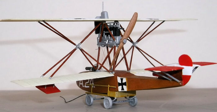
surfaces. The engine was made using laminated card for the block, rod for
the cylinders, and thin rod and stretched sprue for the pipes and
exhausts. I used small pieces of 20 thou card to represent the rocker
covers and rod for the cam shaft. Other small details were added based
on photos of the engine and the whole was painted before I attempted to
mount it.
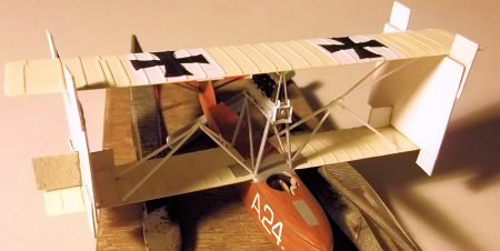
In my opinion it is essential to paint biplanes before adding the top
wing. The fuselage was painted with artists oils: a mixture of burnt
sienna and raw sienna in a ratio of approximately 1:3. These oil paints
take a long time to dry so I placed the model in a drying cupboard for
3-4 days to speed up the process. The hull was then coated with several
thin coats of Revell clear orange acrylic varnish. The wings were
painted with a mixture of Humbrol colours, as were the white squares and
red stripes on the wing and tail surfaces. The crosses were printed on
my home computer but the number and letter on the nose were from
Letraset rub-down transfers. The grey and aluminium were also Humbrol
paints.
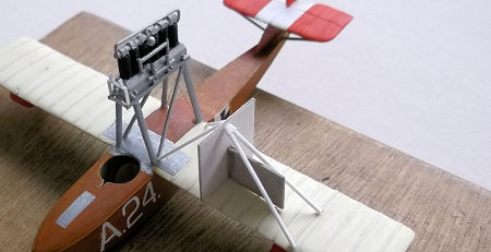 The engine could now be put into place. The challenge of this model was
the wing struts which are not symmetrical when viewed from the front or
rear but have to match or the model will not look right. The strut
arrangement consisted of 4 pairs of tubular steel V struts on each side:
these converged on to a central point where they were welded together.
The struts were filed and sanded from 20 x 30 thou Evergreen strip. I
made 8 small pieces which would form the apexes of the V's and then
used a pair of dividers to measure accurately the spacings of the open
ends of each V where it would attach to the wing or hull. These spacings
were marked on a piece of paper and the arms of the V glued to the apex
piece. In order to get the V's to sit properly on the wings I made a
simple card jig which I could place on the lower wing and rest a V strut
against it. Then while the strut was still setting I put the opposite V
in place and gently removed the jig to allow the apexes of the two V's
to come together. When they touched I dabbed some liquid glue on the
joint and allowed the whole to set. The operation was repeated for the
other side.
The engine could now be put into place. The challenge of this model was
the wing struts which are not symmetrical when viewed from the front or
rear but have to match or the model will not look right. The strut
arrangement consisted of 4 pairs of tubular steel V struts on each side:
these converged on to a central point where they were welded together.
The struts were filed and sanded from 20 x 30 thou Evergreen strip. I
made 8 small pieces which would form the apexes of the V's and then
used a pair of dividers to measure accurately the spacings of the open
ends of each V where it would attach to the wing or hull. These spacings
were marked on a piece of paper and the arms of the V glued to the apex
piece. In order to get the V's to sit properly on the wings I made a
simple card jig which I could place on the lower wing and rest a V strut
against it. Then while the strut was still setting I put the opposite V
in place and gently removed the jig to allow the apexes of the two V's
to come together. When they touched I dabbed some liquid glue on the
joint and allowed the whole to set. The operation was repeated for the
other side.
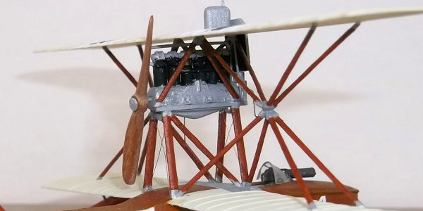
 To
get the top wing into place required the use of two more card jigs. The
had been made so that the edges of the wings would be held parallel and
in alignment fore-aft, and at the correct distance vertically. I rested
the top wing on to the jigs and inserted an outboard V assembly on one
side and then the other. the tiny inverted V in front of the engine
which hold the radiator was put in at this stage. The struts were
allowed to dry before the jigs were carefully removed so that the inner
V 's could be put into place. Finally the main struts from the engine
support frame to the top wing were fixed into place and all were painted
with oil paints. (Although the struts were made from steel tube they
were painted to look like wood on the original machines).
To
get the top wing into place required the use of two more card jigs. The
had been made so that the edges of the wings would be held parallel and
in alignment fore-aft, and at the correct distance vertically. I rested
the top wing on to the jigs and inserted an outboard V assembly on one
side and then the other. the tiny inverted V in front of the engine
which hold the radiator was put in at this stage. The struts were
allowed to dry before the jigs were carefully removed so that the inner
V 's could be put into place. Finally the main struts from the engine
support frame to the top wing were fixed into place and all were painted
with oil paints. (Although the struts were made from steel tube they
were painted to look like wood on the original machines).
The final details could now be added, including the machine gun (a
Schwarzlose from Aeroclub), wing floats which had been shaped from
laminated card, radiator, propellor which I carved from wood, and
gravity tank on the top wing. The only rigging on this model was for the
engine supports and this had been made from 40 SWG rolled copper wire
and fixed before the wing struts were put in place.
 I
suspect that any reader who has got this far will have already concluded
that I am completely mad. However I really did enjoy the challenge of
building this model, not least because I had no idea of how I was going
to solve the strut problem until I came to it. The solution in the end
was quite simple and only required a little care and patience. It shows
that complex and expensive jigs are not necessary to build biplanes,
even form scratch and the result is, I hope, an eye-catching and
original model.
I
suspect that any reader who has got this far will have already concluded
that I am completely mad. However I really did enjoy the challenge of
building this model, not least because I had no idea of how I was going
to solve the strut problem until I came to it. The solution in the end
was quite simple and only required a little care and patience. It shows
that complex and expensive jigs are not necessary to build biplanes,
even form scratch and the result is, I hope, an eye-catching and
original model.
K.
Munson Fighters
1914-1919, Blandford
Press, 1976.
There are several sources on the internet which also provide photos and
further information on this type.
Stephen Foster
21 August 2017
Copyright ModelingMadness.com
Thanks to
for the preview kit. You can find this kit at your favorite hobby shop
or on-line retailer.If you would like your product reviewed fairly and
fairly quickly, please
contact
the editor
or see other details in the
Note to
Contributors.
Back to the Main Page
Back to the Review
Index Page
Back to the Previews Index Page