Frog 1/72 Shackleton AEW.2
| KIT #: | F-172 |
| PRICE: |
65 Danish Kr = US$ 10 |
| DECALS: | Two options |
| REVIEWER: | Torben Plesberg |
| NOTES: | Conversion |
| HISTORY |
The AVRO Shackleton was developed from the AVRO Lincoln bomber
as a long range maritime reconnaissance plane. During WWII the RAF used Lend
Lease B -24s for the very important job of spotting and fighting German
submarines. Since the B-24s after the war according to the Lend Lease
agreement should go back to the USA, the RAF had a problem to find a substitute.
The new aircraft was not just a Lincoln modified for MR. Wings and undercarriage
were the same as the Lincoln. The fuselage was entirely new and much
bigger. The tail plane was moved upwards to make the much bigger fins clear the
ground. The engines were Rolls Royce Griffons, whereas the Lincoln was powered
by Merlins. The new aircraft got its own name after Sir Ernest Shackleton, a
famous British Antarctic explorer. The Shackleton should not have the
shortcomings of the B-24: noisy, cold and cramped interior, and the crew
stations were noise insulated and heated, and there was a resting room with 2
bunks. There was a large weapons bay, with plenty of room for all necessary
hardware for sea operations, including SAR missions.
The Shack, as the Shackleton was called in daily speech, was
built in three main versions: The Mk 1 had a short blunt nose with a big radome
under the chin, and a short tail as the Lincoln. The Mk 2 had a longer nose and
the radome was retractable and situated in the belly aft of the wings. The
tail was also longer and with an observation station in a glazed tail cone. The
Mk 3 had a tricycle landing gear, a redesigned nose with room for the nose
wheel, and a new broader outer wing with tip tanks for better range. Even the
mighty Rolls Royce Griffon engines had not enough power for hot area
operations, and to deal with this problem, two Viper jet engines were installed
in the outer nacelles, and the Shack Mk 3 Phase III became one of a very few
six engined aircraft. The available power for takeoff was boosted considerably
and the aircraft could further more carry a larger load. But the price for this
was a reduced fatigue life for the aircraft.
 In the late sixties the Royal Navy had to cut down their
forces, and the aircraft carriers were one by one put out of service, the last
being the Ark Royal. The carrier based Gannet AEW 3 aircraft were retired
simultaneously. However, the old American radars of the Gannets were not
expendable. The only way to keep these radars going, was to put them on a land
based aircraft. The Shack was the only realistic candidate for this
stop-gap job.
In the late sixties the Royal Navy had to cut down their
forces, and the aircraft carriers were one by one put out of service, the last
being the Ark Royal. The carrier based Gannet AEW 3 aircraft were retired
simultaneously. However, the old American radars of the Gannets were not
expendable. The only way to keep these radars going, was to put them on a land
based aircraft. The Shack was the only realistic candidate for this
stop-gap job.
Twelve Shackleton Mk 2s were modified to AEW 2 standard, and
the aircraft with the fewest flying hours were chosen – practically the same as
the latest produced aircraft. The Mk 3 aircraft were not in question for AEW, as
their fatigue life was too short. The AEWs were assigned to squadron 8, based at
Lossiemouth, a well-known base, because the last raid against the Tirpitz was
launched from here in November 1944, and entered service in 1972. The successor
to the Shacks without AEW, the Nimrod was already in service at that time.
The successor to the AEW Shack was supposed to be the Nimrod AEW Mk 3, with
deliveries beginning in 1983. This project comprising twelve aircraft failed,
however, because of insurmountable problems with the two big search radars, and
the venerable Shacks soldiered on and probably also because the Shack had some
advantages compared with the Nimrod, especially the 4 observation posts,
meaning that the Shack was better suited for spotting survivors in the sea on
SAR missions. The AEW Mk 2 Shacks were in service for 19 years, until the last
five aircraft were finally retired in 1991. The successor to the Shack was the
Boeing Sentry AEW Mk 1, which was ordered in 1986 and with first deliveries late
in 1990. When the Sentry was operational, Sqn. 8 was relocated to Waddington.
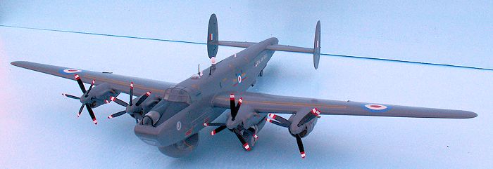
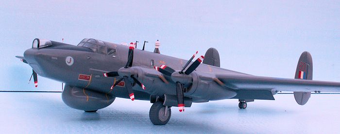
At an open day airshow at Karup Air Base in 1979 I witnessed a flying display by Shackleton AEW 2 WR960. I was very impressed by this big plane with its special sound from the Griffon engines. Some 20 years later I bought the FROG kit from a friend, but it was not until 2013 I started the modeling process of the WR960.
| THE KIT |
The best you can say about the old FROG kit first released in
1967 is, that it is the only injection moulded kit of a Shackleton to a 1/72
scale on the market. All surfaces are extensively covered with real big rivets.
The decaling would be about the same as decaling a hedgehog! The big parts fit
fairly well together. The engine nacelles fit rather badly, and the propellers
need a lot of care, if you want them to fit and turn at
 the same time. The
instruction sheet does its job. The decal sheet is for two aircraft: XF707 of
squadron 206 of the RAF, and 1722 of the South African Air Force, the only other
operator of the Shack. The decals are of a remarkably good quality – even after
+ 45 years on the shelves.
the same time. The
instruction sheet does its job. The decal sheet is for two aircraft: XF707 of
squadron 206 of the RAF, and 1722 of the South African Air Force, the only other
operator of the Shack. The decals are of a remarkably good quality – even after
+ 45 years on the shelves.
The kit has flaps down, but it is of course also possible to get them up, if you want so. The interior is not very detailed, as could be expected, but in my opinion it is waste of time to make details, which cannot be seen, when the model is finished. A problem might be to glue the engine nacelles correctly to the wings, as no stop pins secure the exact position. The long plastic spar to help fastening the wings to the fuselage did not fit properly, and it might be omitted if you use a fast and strong glue. The kit will produce a nice replica of the Mk 3 Shackleton – but only if you remove the rivets! The kit is without the Viper installation.
| CONSTRUCTION |
The first thing to do was to remove all the
rivets. I used a sharp knife and scraped all of the rivets off. During this
procedure I realized that the plastic was brittle, and after a couple of
mishaps, I learned to handle the old kit with the utmost care. I fixed the
mishaps and now it was time to decide which changes were necessary to produce an
AEW 2.
The following modifications were necessary:
1) The front fuselage should have a more shallow
belly
2) The special radome for the AN/APS-20 (F) 1 search
radar was to be made.
3) The outer wings were to be modified to Mk 2
standard wing, including rounded wing tips.
4) The canopy was to be modified, and a pair of new
windows behind the canopy should be added.
5) The undercarriage was to be changed from tricycle
to tail wheel.
6) Decals should be made for WR960
I shall mainly deal with the mentioned modifications, but I
will describe a few items of the standard building procedure because they imply
problems.
 After the de-riveting and assembling and painting of the
Spartan interior, I glued the fuselage together and concentrated on the belly
modification of the fuselage. I marked the piece to be removed with a fiber pen
for the milling operation. At first the fuselage must be firmly fastened
in a vice – without crushing it. I made some support blocks of wood, and these
allowed a firm fastening in the vice. The milling machine did a perfect job. A
block of Ureol was cut into shape, glued to the fuselage and sanded for a
perfect fit.
After the de-riveting and assembling and painting of the
Spartan interior, I glued the fuselage together and concentrated on the belly
modification of the fuselage. I marked the piece to be removed with a fiber pen
for the milling operation. At first the fuselage must be firmly fastened
in a vice – without crushing it. I made some support blocks of wood, and these
allowed a firm fastening in the vice. The milling machine did a perfect job. A
block of Ureol was cut into shape, glued to the fuselage and sanded for a
perfect fit.
The radome was also made of a block of Ureol. The block was
cut in shape seen from the bottom and from the side. Later it was gradually
shaped seen from the front – and this was the most time consuming part of the
entire process. I had no reliable drawing at my disposal, just a sketch from a
publication on RAF aircraft in 1985. In return I had about a dozen photos
gathered from different websites, and my own photos of the real thing. All
I could do was studying the photos and trying to get my Ureol block look the
same. When I had been working on the radome for about half an hour, I put it
away and did something else. Once a week I worked about half an hour on the
radome. After six weeks I found no further shaping necessary. My radome was
finished, not necessarily 100 % correct, but as close I could get according to
my documentation. £ 30 was actually cheap – compared to the time I spent making
the radome!
Another comprehensive operation was to change the
undercarriage. The parts of the kit were useless. The Mk 3 had twin wheels over
all, and the main wheels were far too small for the single main wheels of a tail
wheel undercarriage. Main wheels should be 23 x 7 mm, and tail wheels 8 x 2½ mm.
So - I had to make my own wheels – including the pattern on
the main wheels. The wheels were turned in nylon on my Unimat 3 lathe. This job
was an easy one, the most difficult was to get the curved perimeter right.
Making the pattern was a typical job well suited for the Unimat. The six
longitudinal lines were made with a pointed turning tool.
For the crossing lines I needed the dividing apparatus and I
choose a disc with 36 holes. The cutting device was a 0.2 mm thick 20 mm gauge
circular saw blade. 36 times I carefully moved each wheel through the spinning
saw blade. The lines were, however, too thin to produce a pattern to be seen. So
with a fine triangular needle file I very carefully doubled the size of the 72
0.2 mm lines. Now the wheels were finished and with a nice pattern.
 The next operation was to produce the wheel legs. The material
for this purpose was hard brass wire: gauge 1.5 mm, gauge 1.0 mm and gauge 0.8
mm. In order to get the legs perpendicular and exactly matching each other, I
made a soldering jig. The holes for the wheel shafts were drilled in the end of
the legs using a 0.8 mm drill bit. The soldering job was easily done, thanks to
the jig, the raw legs were finished.
The next operation was to produce the wheel legs. The material
for this purpose was hard brass wire: gauge 1.5 mm, gauge 1.0 mm and gauge 0.8
mm. In order to get the legs perpendicular and exactly matching each other, I
made a soldering jig. The holes for the wheel shafts were drilled in the end of
the legs using a 0.8 mm drill bit. The soldering job was easily done, thanks to
the jig, the raw legs were finished.
Now it was time to place the wheel legs in exactly the right
places in the wheel bays. To do this I made a couple of 4 mm thick Ureol blocks
that would fit into the inner side of the top of the wings in the bays. I marked
carefully for the holes for the legs – and drilled them. Now the complete main
wheel under carriage unit was put into place, and the legs could be adjusted in
length, so each wingtip had exactly the same distance to the ground.
The tail wheel is of the twin type, and was as a matter
of fact very similar to the one I had made for the
Tp 80 Lancaster. The two wheels
were turned in acrylic rod, but the result was not good enough, and I tried once
more. This time I used Ureol, and the result was much better. The leg was
soldered together, and it was a very long one, since it should be placed
somewhere in the inner top of the fuselage beneath the tail plane. First I
marked the opening for the tail wheel on the bottom of the fuselage, and then it
was an easy milling job to make the wheel bay. A small block of Ureol was
shaped to fit the inner side of the dorsal of the fuselage. The hole for the leg
was drilled. I put the leg into the block and then it was quite easy to glue it
in the right place through the small opening, using the leg as a handle. Now it
was time to adjust the length of the leg, so the fuselage would get the right
angle with the ground.
Next operation was to change the wings from Mk 3 to Mk 2. If
you put a ruler along the rear edge of the wing, you draw a line
from the point where the wing disappear under the ruler end to the wing tip.
Then you have got your cut line. After cutting you have to close the gap between
the two wing halves with a piece of plastic strip. Then you place the aileron
and draw a line along the front edge, and cut away what is behind this line. Now
you can place the aileron, the rear edge of which is the same as the rear edge
of the wing. The kit is with movable ailerons, but this is not a toy, and the
aileron should be glued very close to the wing to avoid unrealistic gaps.
The wing tip was sanded smooth and perpendicular before the
new rounded Ureol wing tips were glued in place. The proper fit of the tips
needed some sanding. The Mk 2 wing is from an aesthetic point of view much to
prefer.
The canopy had to be filed and sanded thinner in order to fit
properly to the fuselage opening. Besides the framing is different and has to
be removed completely. I think that the thickness of the transparent
 canopy was
reduced to about half size. To regain the transparency of the canopy, I polished
it with toothpaste. Thank god that the canopy wasn’t brittle at all. On the
contrary it was rather flexible. The new Mk 2 framing was made of 0,8 mm wide
pieces of thin tape.
canopy was
reduced to about half size. To regain the transparency of the canopy, I polished
it with toothpaste. Thank god that the canopy wasn’t brittle at all. On the
contrary it was rather flexible. The new Mk 2 framing was made of 0,8 mm wide
pieces of thin tape.
Behind the canopy there is a big window in either side. The
openings had to be cut very carefully and sanded to the right size and form.
The edges were filed in a small angle, so the outside opening was slightly
larger than the inside opening. The panes were cut out of 1 mm acrylics, and the
edges were filed in an angle corresponding to the openings. In this way it was
possible to glue the panes in place without their falling into the fuselage. All
transparent parts were glued with a clear gloss varnish for the best result.
Now I have dealt with the modifications, I would like to make
some comments on the standard building of the model. The large parts of the kit
fit well together, though it was not up to a modern Tamigawa standard. The
engine nacelles, however, were rather poor, and it took a very long time with
filling and sanding to get an acceptable result. As far as I know the conversion
kit from Aeroclub came with engine nacelles as well. The exhaust pipes were
poor, and I made some new ones of brass tube and wire, and with a piece of one
mm gauge wire to fasten them properly to the nacelles.
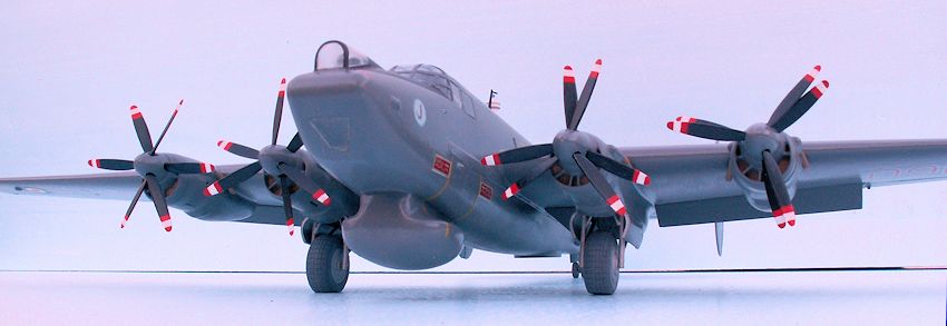
The propellers are a project of its own. It took a lot of work
to drill the holes properly and mill some material off to get everything fit and
run properly. The painting of the propeller blades was quite a challenge. The
tips were not just yellow as usual, but with red-white-red stripes. I sanded the
propeller tips extra thin to avoid they would end up too thick with all the
paint needed. This sanding was done with the utmost care – the propellers were
brittle and a blade might easily break off.
 I did the painting job in this order: The tips were painted
gloss white - twice. Then the rest of the blades were painted flat black –
twice. In order to paint the red stripes properly, I made two painting jigs, one
for the outer propellers, which have a slightly larger gauge, and one for the
inner propellers. With the aid of these accessories I succeeded in making the
red stripes look very much the same on all of the blades. The propeller tips are
a spectacular detail on a Shack – because there are so many of them. Therefore
all the trouble.
I did the painting job in this order: The tips were painted
gloss white - twice. Then the rest of the blades were painted flat black –
twice. In order to paint the red stripes properly, I made two painting jigs, one
for the outer propellers, which have a slightly larger gauge, and one for the
inner propellers. With the aid of these accessories I succeeded in making the
red stripes look very much the same on all of the blades. The propeller tips are
a spectacular detail on a Shack – because there are so many of them. Therefore
all the trouble.
The last detailing: The characteristic ECM aerial situated on the dorsal was a part of the kit, but it needed some sanding to get the structure smaller and to a proper shape. It was painted before being glued in place. The two small black holders for the HF antennas stretching to the top of the fins were also with the kit. Some modelers want even to have the antennas on such a model, but I omit them, because it is not possible to make them thin enough – 0.07 mm gauge. The two white blade VHF antennas were not with the kit, but there were quite simple to make of a piece of 0.3 mm thick white plastic card. It is not necessary to paint them, their inherent color will do. The problem is to handle tiny items like these, but it is possible with flat nose pliers.
| COLORS & MARKINGS |
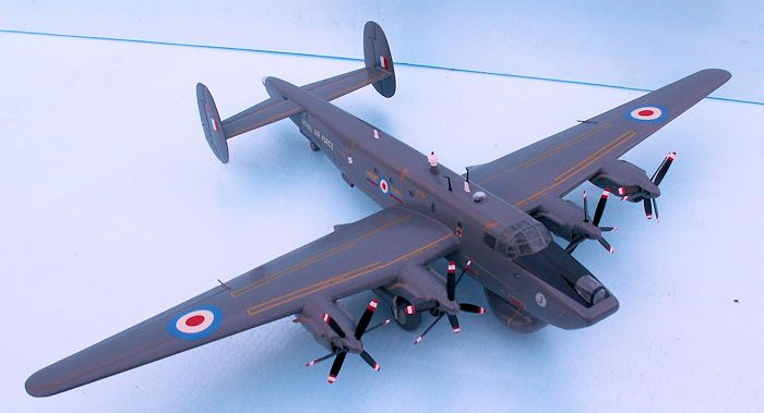
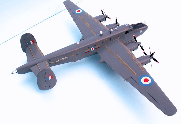
The color scheme of a Shackleton is quite simple: dark sea
gray over all. I used Humbrol HB 164, which dries with a satin finish. In front
of the cockpit there is a flat black antiglare area, HB 33. The interior of the
cockpit and front is cockpit green, HB 78. The wheel bays are painted bare
metal, HB 11, but the color might be light gray – it was not possible to decide
from my documentation. All places to be decaled got a coat of clear gloss
varnish to secure a good adherence. After the decaling, the glossy areas
got a coat of Humbrol satin cote to secure the decals and to match the rest of
the aircraft.
I had, however, a problem with the satin cote, since the
satin effect was random. No matter how much I stirred or thinned – the
satin cote did not produce the satin finish, where I wanted it. Then one day I
tried to warm the bottle of satin cote well before use – to about 30 degrees C.
Quite suddenly the problem was solved: Now I got the satin finish exactly where
my brush had been. My workshop is in a shed, and I do not heat it, unless the
temperature is well below 15 degrees C. Conclusion: the satin cote does not work
if the temperature is too low, and that is below 22 degrees C.
The last big operation was the decaling of the model - I would
not spend £ 70 to get the original Aeroclub decal sheets. So what was usable
from the FROG sheet? The RAF roundels for fuselage and topside of the wings, the
white ROYAL AIR FORCE markings on the rear fuselage, the four fin flashes and
the yellow walk lines on wings and tail planes.
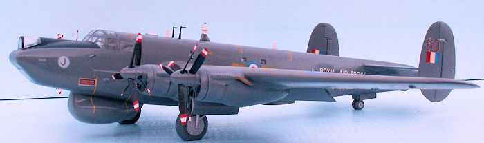
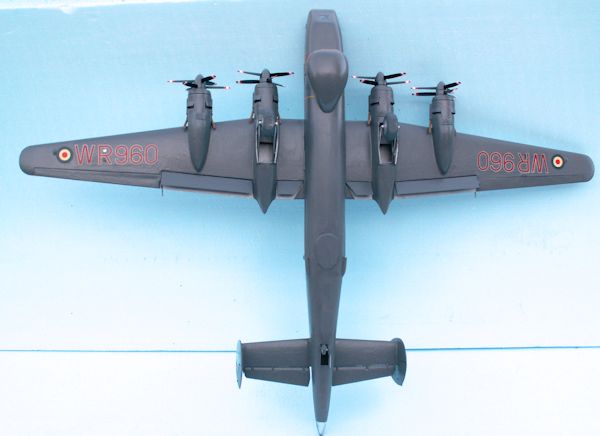
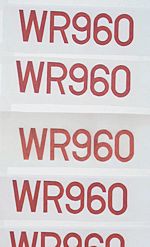
The main problem was how to make the big underwing markings
WR960 in red letters and numbers outlined in white. The smaller WR960 markings
under ROYAL AIR FORCE is red only. At my disposal was: 2 x XF707 and 2 x 206 (Sqn.
206). I only had to produce one W, one R, one 0 and one 9 or 6 to get the
complete markings for the under wings.
The R was made of an F by adding a piece of the rounding from
a 0 and a leg from an X. The W was a bit more tricky, but I had the four 7s, and
these were well suited to produce the W. The 0 was already at hand and the 9 or
6 could be made from the 0 with the missing piece (used for the R) and a piece
from the 0 in 206. (The 6 of 206 would not do, as it was too small.)
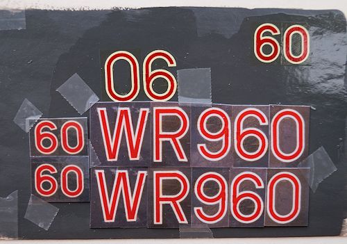 The modified marking letters and numbers were decaled on a
piece of cardboard, which first had been painted dark sea gray. The finished
four signs were copied 4 times. Now I could put 2 x WR960 together. These
markings were photographed with a digital camera, and then I could print them
out upon a sheet of white decal paper. The under wing decals were at hand, and
they were put on the model.
The modified marking letters and numbers were decaled on a
piece of cardboard, which first had been painted dark sea gray. The finished
four signs were copied 4 times. Now I could put 2 x WR960 together. These
markings were photographed with a digital camera, and then I could print them
out upon a sheet of white decal paper. The under wing decals were at hand, and
they were put on the model.
The copying, however, had changed the dark sea gray so much
that it did not match the color on the aircraft, and that was too bad. There was
only one way to solve this problem: with a very fine brush and a very steady
hand, I painted all the spacing between the letters and numbers. Seen at a
distance, it looked OK now. After the satin cote was brushed on, the
result was very convincing, but probably not quite to the £ 70 standard offered
by the original markings from Aeroclub.
The small WR960 marking was cut out from a sheet of cardboard
in a large size, painted red twice (HB 60 scarlet), put on a white background,
photographed with a digital camera and printed on a clear sheet of
 decal paper.
The decal was nice red, but upon the model, it looked black – because of the
dark sea gray color beneath. I tried again and this time overexposing the photo
with two stops. Now I got pink markings, and these looked red on the model.
decal paper.
The decal was nice red, but upon the model, it looked black – because of the
dark sea gray color beneath. I tried again and this time overexposing the photo
with two stops. Now I got pink markings, and these looked red on the model.
The 60 on the fin above the flashes could be made of WR960,
but somewhat smaller. Here I also had to paint the spacing with the dark sea
gray of the aircraft. This operation demanded even more carefulness than the big
underwing markings.
Now the squadron badge was next. It depicts a dagger sheath on
a white disc outlined in light blue. The size for the model should be 7 mm
gauge. I made a large copy of a sketch shown in the magazine dealing with RAF
aircraft in 1985. This was big enough to color the sheath with a
transparent brown watercolor. The light blue circular outline was done with a
circular cutter from a piece of cardboard painted with HB 47 light blue.
The finished badge was copied 6 times, the copies were glued to a plate and
photographed - being overexposed by two stops, and at last printed out on a
white sheet of decal paper, 6 badges 7 mm gauge were at hand.
Next problem was to cut the 7 mm badges out from the decal
sheet. The badges were far too small to cut with a pair of scissors. There
was, however, another way: Just for the purpose I made a special punch from an 8
mm brass tube (inner gauge 7.1 mm) with 8 holes in a short shaft. These holes
permitted light to get inside the punch for a precise visual centering, before
the light blow with the mallet. I made a pair of white discs, too, to place
beneath the badges in order to get the badges as opaque as possible.
The yellow warning stripes for the propellers were simply
pieces of the walk lines of the South African markings. I was rather anxious if
it was possible to place the lines vertically in spite of the curved lines of
the radome. The decals were luckily sufficient flexible, and it was
possible to make the necessary bends.
Next item was to make the warning labels: DANGER PROPELLERS
and with a white arrow pointing in the direction of the danger area. Four pieces
were needed, two with the arrow pointing to the right, and two to the left. I
painted a piece of cardboard a couple of times with HB 60 flat scarlet. I made
the text with white 3.2 mm rubbing letters, which I had in stock from my
production of model warships. The letters were very easy to transfer to
the painted cardboard, even after more than 10 years in the drawer. Actually,
the type
 of letter matched exactly with the original! I made one of each type,
and it was an easy task to print the labels on a clear sheet of decal paper. I
placed the decals on a white rectangular background decal, to get the text and
outline white. The model gained very much in realism with the propeller warning
labels in place.
of letter matched exactly with the original! I made one of each type,
and it was an easy task to print the labels on a clear sheet of decal paper. I
placed the decals on a white rectangular background decal, to get the text and
outline white. The model gained very much in realism with the propeller warning
labels in place.
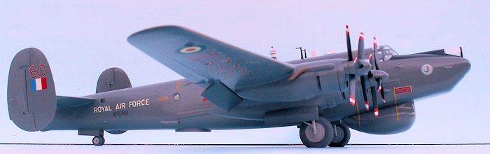
Other markings appeared by searching in my stock. I needed
nine yellow rescue arrow markings. I found these on ESCI sheet no 98: F 101
Voodoo. On either side of the roundels of the fuselage there is a
tricolored band - yellow, red and blue. This is actually a fighter marking. To
understand this you must remember that Squadron 8 used to be a fighter
squadron before the Shacks were assigned! ESCI sheet no 93: Vampire happens to
have markings for a squadron 8 Vampire. How very lucky!
Then I searched for a wing commander badge, which is placed on the fuselage behind the squadron badge, but a little higher. ESCI sheet no 30: Beaufighter has all of the officers’ markings, including wing commander. The quality of the ESCI markings was rather good. I bought about 30 ESCI decal sheets on a sale about 40 years ago, and the price was $ 5 – for all of them! It turned out to be a very good investment. The under wing roundels were also found in my stock, they are the same size as the fuselage roundels.
| CONCLUSIONS |
It was an exciting job to build the Old Gray Lady
of Lossiemouth from the ancient FROG kit. However, I don’t expect that any other
modeler will take the trouble and build an AEW Shack in this way. It
won’t be necessary either: Revell Germany is going to release a brand new kit to
a 1/72 scale of the Shackleton AEW 2 in October this year! I am sure that this
kit will sell well in the UK, where so many people have been flying the Growler,
another popular name for the Shackleton. In the last couple of years there has
been a lot of whispering in Britain that Airfix was going to release a new
Shackleton kit - but Revell turned up to be first and I am looking very
much forward to this kit!
The FROG kit is not recommendable, but it might have a future
among kit collectors.
| REFERENCES |
Chris Ashworth: AVRO’s maritime heavyweight the
Shackleton,
Aston Publications 1990 ISBN 0-946627-16-9
Several walkarounds from the internet
Wikipedia: The AVRO Shackleton
RAF Yearbook 1990. “Displaying the Shackleton” by flight
lieutenant Roger Read no 8 Sqn. Lossiemouth.
ISSN 0954-092X
The Royal Air Force 1985. Aviation News Magazine. Edited by
Alan W Hall.
A comprehensive review of Aircraft, squadrons, bases and
current equipment.
February 2015 If you would like your product reviewed fairly and fairly
quickly, please
contact
the editor
or see other details in the
Note to
Contributors.