| KIT #: | KPK 72041 |
| PRICE: | $30.00 or so |
| DECALS: | Four options |
| REVIEWER: | Joel Hamm |
| NOTES: | Injected plastic, resin details, vacu-formed canopy (2), kabuki tape paint mask. |
| HISTORY |
| THE KIT |
His Editorship, Da Boss, recently reviewed this kit, covering history and contents, eliminating the need to repeat or reiterate anything; so let’s get down to:
| CONSTRUCTION |
 This is a
small kit with a large penchant for mischief and mayhem. Keep the prozac pills
handy. Step 1 on the instructions calls, as usual, for assembling the highly
detailed interior; but the large cockpit opening allows deferment until painting
is complete, simplifying masking; though little in this project is simple.
This is a
small kit with a large penchant for mischief and mayhem. Keep the prozac pills
handy. Step 1 on the instructions calls, as usual, for assembling the highly
detailed interior; but the large cockpit opening allows deferment until painting
is complete, simplifying masking; though little in this project is simple.
Joining the fuselage halves becomes the first task. These parts are petite, with little seam surface and lots of potential to overdo glue application. The spindly tail boom is particularly susceptible to softening and warping. Sticking the right places to the right places is tricky, but the up-side of less seam is less seam mis-match, with just a tad of filling and filing required under the tail and forward of the cockpit.
A logical expectation suggests that inserting the floorboard and bulkhead through the wing opening will hold the fuselage halves in proper position, but those parts form too narrow a cockpit tub, whose correct positioning depends on luck and astrological alignment. It is best to wait until the body is firmly together before slipping in the partial interior from below. The needle-like tail boom also means that the single piece horizontal stabilator surface should wait until the wings are attached to insure parallelism. Ditto the vertical fin for perpendicularity
 Such
attachment presents another major difficulty, owing to the wide bat-wing root
fairings and pronounced beavertail underside. All the join surfaces will need
careful carving and repeated dry fitting, but a pronounced step will still
result where the wing camber overshoots the curve of the fairing. It’s a bit of
a tickle to fill and feather.
Such
attachment presents another major difficulty, owing to the wide bat-wing root
fairings and pronounced beavertail underside. All the join surfaces will need
careful carving and repeated dry fitting, but a pronounced step will still
result where the wing camber overshoots the curve of the fairing. It’s a bit of
a tickle to fill and feather.
While the goop sets up use tape to apply upward tension to the wingtips, else the airplane will emerge sans dihedral.
The next mega-migraine is caused by part #17, the reverse scoop under the engine compartment. It is too narrow to cover the gap between the fuselage halves. Best - or only - solution js closing that opening with a chunk of curved plastic sanded to match the contour of the under-cowl, then gluing the scoop to that.
The cowl design requires that the sharply molded resin radial engine be pre-painted and stuck to the firewall so that the airframe can be painted as a single assembly. The cowl ring is wider and rounder than its mating surface on the fuselage, so the resulting “cheeks” will need filler and sanding.
| COLORS & MARKINGS |
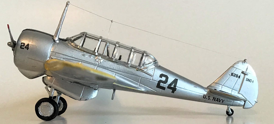
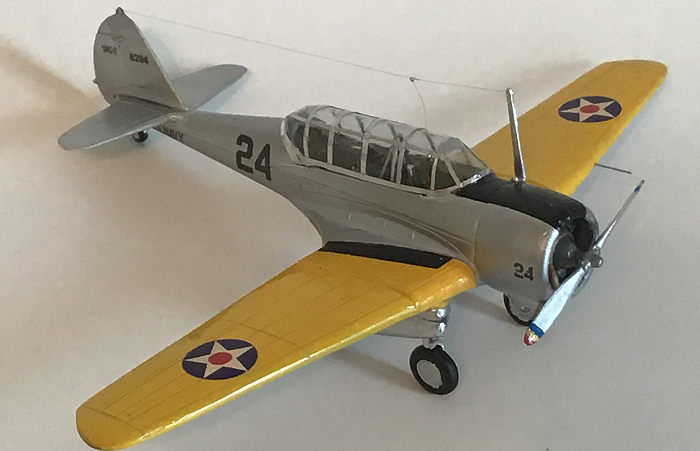
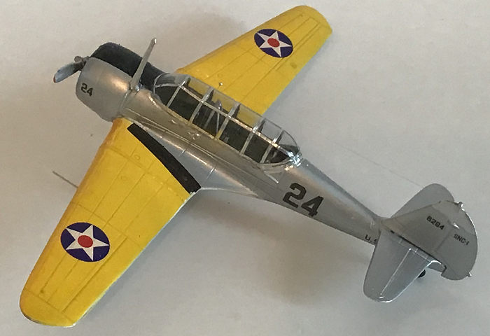
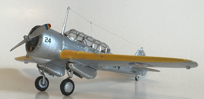
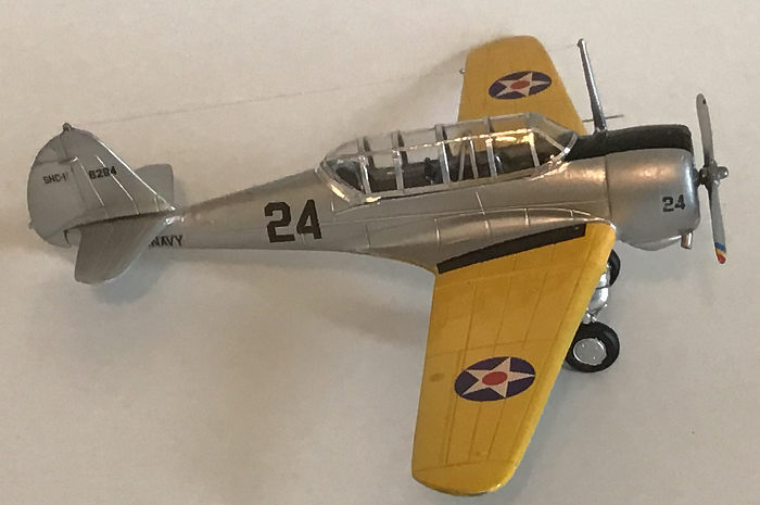
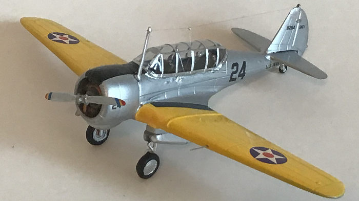
All the surgical
scarring should be hidden under a heavy coat of sea blue over grey, one of the
livery options, but the natural metal / yellow wings is a prettier scheme. With
the cockpit and engine masked, everything was coated in Test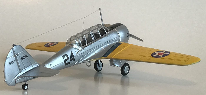 ors
gloss white enamel undercoat. Wings got treated to Square Bottle yellow, and
after blue tape masking everything else was hosed with Testors automotive silver
lacquer, which quickly dries to a chrome sheen, subsequently dulled,
unfortunately, with a post-decal Future / Kleer / Johnsons sealer coat.
ors
gloss white enamel undercoat. Wings got treated to Square Bottle yellow, and
after blue tape masking everything else was hosed with Testors automotive silver
lacquer, which quickly dries to a chrome sheen, subsequently dulled,
unfortunately, with a post-decal Future / Kleer / Johnsons sealer coat.
Decals are printed on a solid clear backing, demanding precise trimming to avoid a silvered surround. Markings are thick, but conform adequately when coaxed by physical pressure. Micro-Sol and / or Solvaset will soften them, but no guarantee is implied that they will uncrinkle when dry. The decal sheet includes four mysterious blue/yellow rectangles. Eventually the realization hit that these were the propeller tip warning stripes, for some reason minus the red portion. Painting on the entire tri-color was easier than fiddling with the partial transfers.
Another mystery is why marking alternatives are offered for 3 aircraft differing only in serial number. The space on the decal sheet could better have been devoted to black wing walks; not included but easily cut and pasted from pieces scrounged from the spares bin.
| FINAL CONSTRUCTION |
At this point all the cockpit furnishings can be added. The kit makers went overboard here, including invisible bits such as rudder pedals and parts 5 - oxygen tanks. Or perhaps they held helium for filling party balloons. Color photos of museum machines show that the interior was painted light grey, so I gave way to laziness and left most pieces in bare plastic.
 GOOGLE
research also indicates that SNC’s came with 2 canopy versions: the 3-pane
arrangement with slanted framing depicted on the box art, and the 4- side-panel
glazing molded into the 2 vacanopies.
GOOGLE
research also indicates that SNC’s came with 2 canopy versions: the 3-pane
arrangement with slanted framing depicted on the box art, and the 4- side-panel
glazing molded into the 2 vacanopies.
More mysteries: Also provided is a swatch of kabuki painting masks, but they consist only of 2 curved strips that match and mask nothing. Perhaps these are supposed to be cut into individual polygons. In any event they are useless. Framing is more easily done with slivers of metal foil HVAC tape, which realistically represents the aluminum strips that held the plexi in place on the real thing. After the tape is applied a dunking in Future softens the edges and prevents creeping.
After going through
those machinations I found that the transparency was too wide to fit the cockpit
opening. Clamping and squeezing couldn’t convince the sides to stick where they
should be stuck, so I settled on rolling my own. I filled the canopy with water
based putty to form a male mold, sanded it to proper contour, which removed
framing lines, and set up the vacu-former rig. Multiple tries at melting the
acetate to the proper gooiness without starting a conflagration eventually
yielded a greenhouse that fit perfectly - except around
 the
windshield where I hopelessly botched the trim job. Before try - trying again I
succumbed to a modeler’s hunch and had a go at the alternate kit canopy, which
turned out to be molded narrower, and fit acceptably with only minimal coaxing,
clamping, and cursing. Go figure.
the
windshield where I hopelessly botched the trim job. Before try - trying again I
succumbed to a modeler’s hunch and had a go at the alternate kit canopy, which
turned out to be molded narrower, and fit acceptably with only minimal coaxing,
clamping, and cursing. Go figure.
As with every Kora / Dora / LF kit I’ve built, the landing gear struts are too long and need lopping by about 2 or 3 millimeters. The Czechs must have a thing for long legs.
Torque links come from the resin stubs and need considerable cleaning. If Edward, Airwaves, or one of the other after-marketers is listening, what the world desperately needs is a fret of photo-etched landing gear torque links. They’re a small detail that makes a big difference in building a model airplane that doesn't look like the toy it really is.
Landing gear doors at first appear interchangeable, but there are long ones that go outboard and shorter ones to go on the inside. Or is it the other way around? Just follow the part number and instruction sheet and you’ll do fine. For a change the diagrams are actually readable and helpful.
A few last gimcracks and doo-dads complete the project. If you are a stickler for accuracy with time and patience to spare, go ahead and string the antenna wire.
| CONCLUSIONS |
 “Not for
children. Only for experienced modelers.” It says that right on the box top.
“Not for
children. Only for experienced modelers.” It says that right on the box top.
23 August 2019
Copyright ModelingMadness.com
If you would like your product reviewed fairly and fairly quickly, please contact the editor or see other details in the Note to Contributors.