Sierra Models 1/48 Curtiss F6C Hawk
| KIT #: | 48-007 |
| PRICE: | $ |
| DECALS: | None |
| REVIEWER: | Carmel J Attard |
| NOTES: | Vacuform with metal parts. |
| HISTORY |
 hese
were intended originally for shore use by the US Marine Corps. In fact only five
aircraft were delivered as F6C-1, the remaining four being completed as F6C-2
(Model 34 D) standard, strengthened for carrier operations and were then fitted
with arrestor hook. During 1927 the USN obtained 35 examples of F6C-3, a
modified version of the F6C-2. These aircraft were followed by 31 examples of
F6C-4
hese
were intended originally for shore use by the US Marine Corps. In fact only five
aircraft were delivered as F6C-1, the remaining four being completed as F6C-2
(Model 34 D) standard, strengthened for carrier operations and were then fitted
with arrestor hook. During 1927 the USN obtained 35 examples of F6C-3, a
modified version of the F6C-2. These aircraft were followed by 31 examples of
F6C-4
The Hawk F6C-3 fighters were flown from 1928 by the VF-5F squadron, which became VB-1B in July of that year in difference to the Hawk’s intended fighter-bomber role, on the carrier USS Lexington. For a short period VB-1B operated its F6C-3machines as twin-float seaplanes. Other F6C-3 warplanes served with shore based VF-8M squadron of the US Marine Corps.
The US Navy decided that the maintenance of water-cooled engines on board carriers presented unwarranted problems, with the result that the radial engined F6F-4 was used to equip the VF-2B. The aircraft were then passed to USMC units. Four F6C-2s were converted from F6C-1 standard for carrier operations and operated from USS Langley.
| THE KIT |
 The kit
follows one familiar Sierra lines where the fuselage is split vertically and the
flying surfaces split top and bottom. Contained in a polythene bag a vac moulded
styrene sheet that contained all the vac form parts. These have reasonable
surface finish with fine panel lines. Brief assembly guidelines are given and
adequate 1/48 scale plans provide three-plan views and marking detail, which
come on a two-page instruction sheet. Alternative undercarriage gear assembly is
suggested for types F6C-1, -2 and –3. Also included are front and side views for
F6C-3 on a pair of floats.
The kit
follows one familiar Sierra lines where the fuselage is split vertically and the
flying surfaces split top and bottom. Contained in a polythene bag a vac moulded
styrene sheet that contained all the vac form parts. These have reasonable
surface finish with fine panel lines. Brief assembly guidelines are given and
adequate 1/48 scale plans provide three-plan views and marking detail, which
come on a two-page instruction sheet. Alternative undercarriage gear assembly is
suggested for types F6C-1, -2 and –3. Also included are front and side views for
F6C-3 on a pair of floats.
| CONSTRUCTION |
At an early stage one need to decide which type to build from the variants provided for which parts includes those for F6C-1,2,3 and float plane version. Vac-form parts are first cut and sanded to correct shape as applicable. Assembly is straight forward for those used to vac form type of models and care was particularly taken when opening up cockpit and the fuselage sides opening to take the exhaust stack.
 The cockpit
was detailed with a seat, control stick, rudder pedals and instrument panel. A
headrest was added and made from a thin section cut from a round sprue. The
lower wing halves are first glued and locating pegs are added at the root ends
made from short length metal pieces. These will be inserted inside pre drilled
holes at lower fuselage at a later stage. The same was repeated to tail planes
providing a secure joint in each case. Interior metal structure was not viable
to add since little could be seen from the cockpit opening, as this will be
blanked with addition of a figure.
The cockpit
was detailed with a seat, control stick, rudder pedals and instrument panel. A
headrest was added and made from a thin section cut from a round sprue. The
lower wing halves are first glued and locating pegs are added at the root ends
made from short length metal pieces. These will be inserted inside pre drilled
holes at lower fuselage at a later stage. The same was repeated to tail planes
providing a secure joint in each case. Interior metal structure was not viable
to add since little could be seen from the cockpit opening, as this will be
blanked with addition of a figure.
The metal exhaust stack that goes on each side of engine were cleaned and inserted in the slot prepared to take them. These were glued at a downward angle as viewed from the front. Interior was painted silver and fuselage halves were then closed. A tube-aiming site added to forward of windshield. Tailskid added from a measured length of metal wire. Short lengths of metal tubes were fitted to gun ports located on top of nose area.
A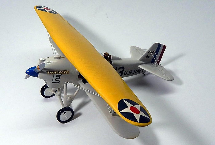 ttention
was turned to the undercarriage. The landing gear struts were partly provided
from vac form parts and the central struts built and shaped from sprues. Wheel
axle made out of a short piece of metal 3/16 inches in length. These were
inserted to the end part of struts to take the wheels centre holes.
ttention
was turned to the undercarriage. The landing gear struts were partly provided
from vac form parts and the central struts built and shaped from sprues. Wheel
axle made out of a short piece of metal 3/16 inches in length. These were
inserted to the end part of struts to take the wheels centre holes.
After lower wings were joined to the fuselage the outer wing struts position was marked on the lower wings. The distance in between the wings was measured and a distance piece made out of balsa was taped temporally to hold upper wing in place while the outer struts were added in place. With whole structure gaining strength then holes were drilled to take the twin parallel rigging. I used fine fishing line for rigging. It was repeated to the fin to tail planes rigging, and also to the control lines for elevators. With rigging complete the rigging holes were glued, filled op and sanded flat. Next stage was joining of gear struts to fuselage and adding the inner fuselage struts in their respective place and the central blank distance piece removed. Gear struts added and belly fuel tank glued in place.
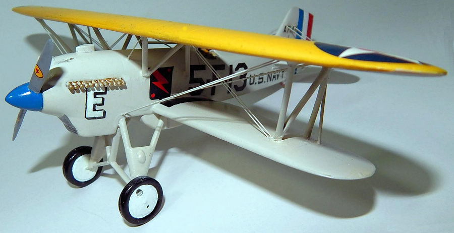
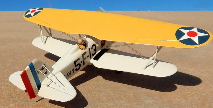
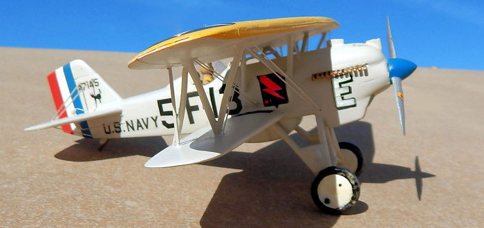
| COLORS & MARKINGS |
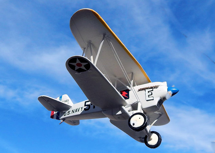 Rudder was
sprayed red, white and blue and after drying this was masked. Cockpit opening
also blanked so that the upper wing sprayed with white base coat followed by
yellow. After paint dried top wing masked and the whole model was sprayed with a
mix of light gray consisting of 60% gull and 40% white. Decals came from spares
box to represent a land based Hawk of VF-5, 1927. The forward white letter
shaded black and ‘alerted cat’ motif on tail fin were hand painted. Model was
finally given an overall coat of Model Master satin lacquer.
Rudder was
sprayed red, white and blue and after drying this was masked. Cockpit opening
also blanked so that the upper wing sprayed with white base coat followed by
yellow. After paint dried top wing masked and the whole model was sprayed with a
mix of light gray consisting of 60% gull and 40% white. Decals came from spares
box to represent a land based Hawk of VF-5, 1927. The forward white letter
shaded black and ‘alerted cat’ motif on tail fin were hand painted. Model was
finally given an overall coat of Model Master satin lacquer.
| CONCLUSIONS |
This is a unique subject from the mid 20s era and a type unlikely to be seen at this scale by kit suppliers from mainstream section. Still I feel that no Navy model section is complete unless it has representation of 1920s era of planes like the Hawk P6. The kit can be made in many forms and is fully up to high standard linked with the name of Sierra.
5 February 2019
Copyright ModelingMadness.com If you would like your product reviewed fairly and fairly quickly, please
contact
the editor
or see other details in the
Note to
Contributors.
Back to the Main Page
Back to the Review
Index Page
Back to the Previews Index Page